1
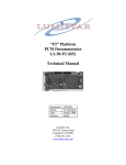
SAG584000300
System Application Guide
NetSure™ 4015 30kW 400V DC Power System
Spec. No. 584000300 (Model 4015-X003)
Issue AB, April 5, 2013
Home
SYSTEM OVERVIEW
Description:
400V DC Output @ up to 30kW Power System
The NetSure™ 4015, 30kW DC Power System is a complete integrated power system
containing rectifiers, intelligent control, metering, monitoring, and distribution. The
individual system sub-racks can be factory integrated into a standard 19” IT rack or
provided separately for customer integration into an existing IT rack.
This power system is capable of operating either with or without batteries online.
This system consists of the following components.
Power and Control Sub-Rack (List 11, 12)
The system contains one (1) “power and control sub-rack”, which houses up to two
(2) rectifiers and the system control and monitoring components.
Rectifier(s)
The system contains one (1) or two (2) rectifiers, which provide load power,
battery float current, and battery recharge current during normal operating
conditions. Refer to the rectifier instructions (UM1R40015000e) for more
information.
Controls
ACU+ (Advanced Control Unit Plus) Controller
The system controller provides power system control, rectifier control (including a
charge control function), metering functions, monitoring functions, and
local/remote alarm functions. Power system control includes battery low voltage
disconnect (BLVD) functionality to remotely trip battery circuit breakers which
protects batteries against over-discharge. The system can also be equipped with
one (1) or two (2) temperature probe(s). Any combination of the two (2)
temperature probes can be programmed to monitor ambient air temperature
and/or battery temperature. A temperature probe set to monitor battery
temperature can also be used for the rectifier battery charge temperature
compensation feature and/or BTRM (battery thermal runaway management)
feature. The controller also provides data acquisition, system alarm
management, and advanced battery and energy management. The controller
contains an LCD display and keypad for local access. The controller provides
Ethernet connection and supports
software upgrade via its USB port. It also
comes with a comprehensive web page
and SNMP capability for remote system
management. Refer to the ACU+
controller instructions (UM1M820NNB-1)
for more information.
System Shutdown
A “System Shutdown” pushbutton is
located on the front of the power and
control sub-rack. When momentarily
depressed, the rectifier’s AC input circuit
breakers and the Emerson provided
battery trays’ battery disconnect circuit
breakers are tripped open to isolate the
system from all electrical sources.
Manual intervention is required to restart
the system.
Page 1 of 32
This document is property of Emerson Network Power, Energy Systems, North America, Inc. and contains confidential and proprietary information owned by Emerson Network Power, Energy
Systems, North America, Inc. Any copying, use, or disclosure of it without the written permission of Emerson Network Power, Energy Systems, North America, Inc. is strictly prohibited.
SAG584000300
Issue AB, April 5, 2013
System Application Guide
NetSure™ 4015 30kW 400V DC Power System
Spec. No. 584000300 (Model 4015-X003)
Home
Load Distribution Sub-Rack(s) (List 21-24)
The system may contain up to two (2) “load distribution sub-racks”, which provide DC
distribution through circuit breakers. Optional main row breaker required for UL
applications. Distribution can also be bulk with no “distribution sub-rack”.
Battery Tray(s) (List 91, 92)
The system may contain up to five (5) battery trays, each housing one (1) 400V
battery string consisting of twenty-eight (28) 12V battery blocks (336V nominal).
Customer supplied external battery strings can be connected to the system. The
total number of internal and external battery strings cannot exceed five (5).
IT Rack Integration (List R1, R2)
Choice of 24U or 42U rack, also includes factory installation, integration, and testing
of all selected components.
Available Grounding Configurations
HRMG (High Resistance Midpoint Ground) Configuration (+/- 200V DC)
The HRMG configuration provides system voltages to ground at half of the output
system voltage, for additional personnel safety. That is, the HRMG version of
400V DC produces +/-200V DC to ground potentials. This configuration is used in
applications where an internal high resistance path is required between the positive
output busbar and site ground and also the negative output busbar and site ground.
The DC bus is continuously monitored for ground fault conditions. If the insulation
resistance between the +BUS or -BUS to ground goes below a set value, a ground
fault alarm is generated. (Refer to UM584000300 [Operation Instructions] for
additional information on this topic.)
NPG (Negative Pole Ground) Configuration (+400V, -0V DC)
This configuration is used in applications where the negative output busbar is
required to be connected to site ground.
Complete Solution
(components factory installed
in an Emerson Network
Power DCM IT Rack)
Individual Components
Page 2 of 32
This document is property of Emerson Network Power, Energy Systems, North America, Inc. and contains confidential and proprietary information owned by Emerson Network Power, Energy
Systems, North America, Inc. Any copying, use, or disclosure of it without the written permission of Emerson Network Power, Energy Systems, North America, Inc. is strictly prohibited.
System Application Guide
NetSure™ 4015 30kW 400V DC Power System
Spec. No. 584000300 (Model 4015-X003)
General Specifications
Family:
System Spec. No.:
System Model:
System AC Input Voltage
System Output Voltage (max.):
Output Capacity:
System:
Rectifier:
System Agency Approval:
EMI:
Framework Type:
Mounting Width:
Mounting Depth:
Power and Control Sub-Rack:
Load Distribution Sub-Rack:
Battery Tray:
24U Rack Dimensions:
42U Rack Dimensions:
Access:
Control:
Color:
Environment:
SAG584000300
Issue AB, April 5, 2013
Home
NetSure™
584000300
4015-X003
Nominal 380/400/480 volts AC, three phase, 50/60 Hz, with an
operating range of 260 to 530 volts. Acceptable input frequency
range is 45 to 65 Hz. A single 4-wire (no neutral) AC input feed
supplies both rectifiers.
400V DC
89A, 30kW (maximum)
44.6A @ 336V DC to 37.5A @ 400V DC, 15kW (maximum)
UL Listed per UL60950-1 (cUL for Canada). CE Marking per low
voltage directive (EN60950) and the EMC directive.
(See “1.5.1 Safety Compliance” on page 27.)
EN 300 386, Class A and FCC Part 15, Class A
Rack Mounting in an IT Rack (EIA-310-D Compliant)
19 Inches (483mm), nominal
724mm (28.5 inches)
257mm (10 inches), HRMG Configuration
317mm (12.5 inches), NPG Configuration
838mm (33 inches)
1194mmH x 600mmW x 1000mmD (47"H x 24"W x 40"D)
2000mmH x 600mmW x 1000mmD (79"H x 24"W x 40"D)
Front and rear for installation and maintenance.
Front for operation.
Microprocessor
Black
-5°C to +45°C (+23°F to +113°F).
Full Rating: -5°C to +35°C (+23°F to +95°F).
Note: Battery manufacturers recommend an operating temperature
of 25°C (77°F). Ambient temperatures higher than this reduce
battery life; temperatures lower than this reduce battery capacity.
For optimal battery performance and service life, battery temperature
should be maintained between +20°C to +25°C (+68°F to +77°F).
See detailed specifications on page 26.
Customer Supplied IT Rack Guidelines
If you plan to assemble / configure your own system, note that the NetSure 4000 Series components
(power and control sub-rack / load distribution sub-rack / battery tray) were evaluated as a UL Listed
system in an Emerson Network Power DCM IT Rack in an ambient of +35°C (95°F), with a front and rear
door free area ratio of 83%.
Page 3 of 32
This document is property of Emerson Network Power, Energy Systems, North America, Inc. and contains confidential and proprietary information owned by Emerson Network Power, Energy
Systems, North America, Inc. Any copying, use, or disclosure of it without the written permission of Emerson Network Power, Energy Systems, North America, Inc. is strictly prohibited.
SAG584000300
Issue AB, April 5, 2013
System Application Guide
NetSure™ 4015 30kW 400V DC Power System
Spec. No. 584000300 (Model 4015-X003)
TABLE OF CONTENTS
SYSTEM OVERVIEW................................................................................................................................................. 1
TABLE OF CONTENTS ............................................................................................................................................. 4
MAIN COMPONENTS ILLUSTRATIONS .................................................................................................................. 6
Factory System Integration – Lists R1 and R2 (Assembled System) ............................................................ 6
Customer System Integration – Installed in Customer IT Rack ..................................................................... 6
Power and Control Sub-Rack - Lists 11 (HRMG) and List 12 (NPG) .............................................................. 7
Load Distribution Sub-Rack – List 21-24 .......................................................................................................... 8
Battery Tray - List 91 (HRMG) and List 92 (NPG) ............................................................................................. 9
LIST DESCRIPTIONS .............................................................................................................................................. 10
Power and Control Sub-Rack ........................................................................................................................... 11
List 11: Power and Control Sub-Rack – HRMG (High Resistance Midpoint Grounded) Systems ............... 11
List 12: Power and Control Sub-Rack – NPG (Negative Pole Grounded) Systems ..................................... 11
Load Distribution Sub-Rack ............................................................................................................................. 12
List 21: Load Distribution Sub-Rack with Row Breaker – HRMG (High Resistance Midpoint
Grounded) Systems ....................................................................................................................................... 12
List 22: Load Distribution Sub-Rack with Row Breaker – NPG (Negative Pole Grounded) Systems .......... 12
List 23: Load Distribution Sub-Rack without Row Breaker – HRMG (High Resistance Midpoint
Grounded) Systems ....................................................................................................................................... 13
List 24: Load Distribution Sub-Rack without Row Breaker – NPG (Negative Pole Grounded)
Systems .......................................................................................................................................................... 13
Battery Tray........................................................................................................................................................ 14
List 91: Battery Tray – HRMG (High Resistance Midpoint Grounded) Systems .......................................... 14
List 92: Battery Tray – NPG (Negative Pole Grounded) Systems ................................................................ 14
Temperature Probes ......................................................................................................................................... 15
List 98: Temperature Probe, 12 Feet (4m) Total Cable Length ..................................................................... 15
List 99: Temperature Probe, 33 Feet (10m) Total Cable Length ................................................................... 15
Rack Integration (Factory Integrated System) ............................................................................................... 16
List R1: 24U, 19” ........................................................................................................................................... 16
List R2: 42U, 19” ........................................................................................................................................... 16
ACCESSORY DESCRIPTIONS ............................................................................................................................... 17
DC Load Distribution Devices .......................................................................................................................... 17
DIN-Rail Type Load Circuit Breakers ............................................................................................................. 17
Load Circuit Breaker Lockout/Tagout Assembly ............................................................................................ 18
User Replaceable Components ....................................................................................................................... 19
ONE LINE DIAGRAM............................................................................................................................................... 20
RECOMMENDED WIRING SIZES, BRANCH CIRCUIT PROTECTION, AND CRIMP LUGS ............................... 21
Equipment Grounding ...................................................................................................................................... 21
Factory Furnished IT Rack Frame Grounding ............................................................................................... 21
Sub-Rack Frame Grounding (for systems installed in a customer furnished IT rack) ................................... 21
Return Busbar (-Bus) Grounding (NPG Configurations Only) ....................................................................... 22
AC Input (Power and Control Sub-Rack) ........................................................................................................ 23
DC Load Distribution (Distribution Sub-Rack) ............................................................................................... 24
DC Load Distribution (Bulk Output from Power and Control Sub-Rack) .................................................... 25
External Controller Interface (Distribution Sub-Rack)................................................................................... 25
Battery (Power and Control Sub-Rack) ........................................................................................................... 25
SPECIFICATIONS.................................................................................................................................................... 26
1. System ........................................................................................................................................................... 26
1.1 System DC Output Ratings...................................................................................................................... 26
1.2 System AC Input Ratings......................................................................................................................... 26
1.3 System Environmental Ratings ............................................................................................................... 26
Page 4 of 32
This document is property of Emerson Network Power, Energy Systems, North America, Inc. and contains confidential and proprietary information owned by Emerson Network Power, Energy
Systems, North America, Inc. Any copying, use, or disclosure of it without the written permission of Emerson Network Power, Energy Systems, North America, Inc. is strictly prohibited.
System Application Guide
NetSure™ 4015 30kW 400V DC Power System
Spec. No. 584000300 (Model 4015-X003)
SAG584000300
Issue AB, April 5, 2013
1.4 Physical.................................................................................................................................................... 26
1.5 System Compliance Information .............................................................................................................. 27
2. Rectifier.......................................................................................................................................................... 27
3. ACU+ Controller ............................................................................................................................................ 27
MECHANICAL SPECIFICATIONS .......................................................................................................................... 28
Rack Integrated System (24U) (List R1) .......................................................................................................... 28
Rack Integrated System (42U) (List R2) .......................................................................................................... 28
Dimensions and Weights .................................................................................................................................. 29
RELATED DOCUMENTATION ................................................................................................................................ 31
BATTERY MANUFACTURER INFORMATION ...................................................................................................... 31
Page 5 of 32
This document is property of Emerson Network Power, Energy Systems, North America, Inc. and contains confidential and proprietary information owned by Emerson Network Power, Energy
Systems, North America, Inc. Any copying, use, or disclosure of it without the written permission of Emerson Network Power, Energy Systems, North America, Inc. is strictly prohibited.
SAG584000300
Issue AB, April 5, 2013
System Application Guide
NetSure™ 4015 30kW 400V DC Power System
Spec. No. 584000300 (Model 4015-X003)
Home
MAIN COMPONENTS ILLUSTRATIONS
Factory System Integration – Lists R1 and R2 (Assembled System)
Note: Also order individual sub-racks List 11, 12, 21, 22, 23, 24, 91, 92;
not to exceed 24U for List R1 and 42U for List R2.
See List Descriptions on page 10.
List R2:
Complete Solution
(components factory installed
in Emerson Network Power
DCM 42U IT rack)
List R1:
Complete Solution
(components factory installed
in Emerson Network Power
DCM 24U IT rack)
Doors/Sides Removed
in Illustration for Clarity
Customer System Integration – Installed in Customer IT Rack
Note: Order List 11, 12, 21, 22, 23, 24, 91, 92.
See List Descriptions on page 10.
Load Distribution Sub-Rack(s)
(6U each)
(List 21, 22, 23, 24)
Power and Control Sub-Rack
(6U)
(List 11 and 12)
Optional Battery Tray(s)
(4U each)
(List 91 and 92)
Page 6 of 32
This document is property of Emerson Network Power, Energy Systems, North America, Inc. and contains confidential and proprietary information owned by Emerson Network Power, Energy
Systems, North America, Inc. Any copying, use, or disclosure of it without the written permission of Emerson Network Power, Energy Systems, North America, Inc. is strictly prohibited.
System Application Guide
NetSure™ 4015 30kW 400V DC Power System
Spec. No. 584000300 (Model 4015-X003)
SAG584000300
Issue AB, April 5, 2013
Home
Power and Control Sub-Rack - Lists 11 (HRMG) and List 12 (NPG)
Battery Leads Openings for
19mm (0.75”) Conduit
(top and bottom)
AC Input Leads Opening
for 25mm (1”) Conduit
Alarm Leads Opening
for 25mm (1”) Conduit
DC Output Leads Openings
for 32mm (1.25”) Conduit
System Shutdown Button
Rectifier Module
AC Input Circuit Breakers
(40A, 380V/400V/480V AC)
Adjustable
Rear Mounting
Brackets
Front
Front Mounting Flanges
Rectifier Modules
ACU+ Controller
ACU+ Interface Board (IB2)
(behind cover)
AC Input
Battery
Terminals
Shunt
AC Surge
Protectors
Battery Terminals
(5 sets of studs
for double hole
lugs, each polarity)
DC Output Terminals
(2 sets of studs
for double hole
lugs, each polarity)
External and Internal
Battery Tray Control/Alarm
Connectors
HRMG Ground Connection
(HRMG Configurations Only)
(MUST BE PROPERLY
CONNECTED TO GROUND)
Rear
Sub-Rack Grounding Stud
Removable Panels
(for installation)
Page 7 of 32
This document is property of Emerson Network Power, Energy Systems, North America, Inc. and contains confidential and proprietary information owned by Emerson Network Power, Energy
Systems, North America, Inc. Any copying, use, or disclosure of it without the written permission of Emerson Network Power, Energy Systems, North America, Inc. is strictly prohibited.
SAG584000300
Issue AB, April 5, 2013
System Application Guide
NetSure™ 4015 30kW 400V DC Power System
Spec. No. 584000300 (Model 4015-X003)
Home
Load Distribution Sub-Rack – List 21-24
List
21
22
23
24
Row Breaker
X
X
HRMG NPG
X
X
X
X
DC Distribution
Input Leads
(from Power and
Control Sub-Rack)
HRMG Configuration
Distribution Blocks hold factory wiring
in unused breaker locations for ease
of adding future circuit breakers.
(both HRMG and NPG)
DC Distribution
Circuit Breakers - 9 positions
(4A, 6A, 8A, 10A, 16A, 20A,
25A, 32A, 40A, 50A, 63A)
Front
Front
Mounting
Flanges
Optional (List 21, 22)
Row DC Distribution
Circuit Breaker (125A)
Future Circuit
Breaker Mounting
Positions
NPG Configuration
Customer
Load Connections
to DC Distribution
Circuit Breakers
Customer
Load Connections
to DC Distribution
Circuit Breakers
Customer
Load Return
Connections
to Return Bar
Conduit Grounding Points
(opposite side also)
(both HRMG and NPG)
Front
Removable Panel
(for installation)
(both HRMG and NPG)
Front
DC Distribution Leads Openings
for 25mm (1”) Conduit
(snap bushings are furnished
for use without conduit)
Rear
Sub-Rack
Grounding Stud
Rear
Return Bar
Grounding Point
(opening for 19mm [0.75"]
conduit provided)
Sub-Rack
Grounding Stud
Removable
Panel
Page 8 of 32
This document is property of Emerson Network Power, Energy Systems, North America, Inc. and contains confidential and proprietary information owned by Emerson Network Power, Energy
Systems, North America, Inc. Any copying, use, or disclosure of it without the written permission of Emerson Network Power, Energy Systems, North America, Inc. is strictly prohibited.
System Application Guide
NetSure™ 4015 30kW 400V DC Power System
Spec. No. 584000300 (Model 4015-X003)
SAG584000300
Issue AB, April 5, 2013
Home
Battery Tray - List 91 (HRMG) and List 92 (NPG)
Battery Tray
Battery Retaining Bracket
(shipped installed, remove to
install battery sub-trays)
View of Individual
Battery Sub-Tray
Six (6) Removable Battery Sub-Trays
Four (4) trays equipped with five (5) 12V DC battery blocks.
Two (2) trays equipped with four (4) 12V DC battery blocks.
Battery blocks in each tray are factory wired.
Battery Sub-Trays
Battery wiring connectorized
for easy installation.
Battery Sub-Tray Connector
Battery Tray Connector
Rear
Battery Tray
Power Cables
Tray Grounding Stud
Battery Tray
Control/Alarm
Harness
Adjustable
Rear Mounting
Brackets
Front
Front
Mounting
Flanges
Battery Breaker (40A)
Page 9 of 32
This document is property of Emerson Network Power, Energy Systems, North America, Inc. and contains confidential and proprietary information owned by Emerson Network Power, Energy
Systems, North America, Inc. Any copying, use, or disclosure of it without the written permission of Emerson Network Power, Energy Systems, North America, Inc. is strictly prohibited.
SAG584000300
Issue AB, April 5, 2013
System Application Guide
NetSure™ 4015 30kW 400V DC Power System
Spec. No. 584000300 (Model 4015-X003)
Home
LIST DESCRIPTIONS
List
Number
Part
Number
11
58400030011
Power and Control Sub-Rack – HRMG
(High Resistance Midpoint Grounded) Systems
6U
12
58400030012
Power and Control Sub-Rack – NPG
(Negative Pole Grounded) Systems
6U
21
58400030021
Load Distribution Sub-Rack with Row Breaker – HRMG
(High Resistance Midpoint Grounded) Systems
6U
22
58400030022
Load Distribution Sub-Rack with Row Breaker – NPG
(Negative Pole Grounded) Systems
6U
23
58400030023
Load Distribution Sub-Rack without Row Breaker – HRMG
(High Resistance Midpoint Grounded) Systems
6U
24
58400030024
Load Distribution Sub-Rack without Row Breaker – NPG
(Negative Pole Grounded) Systems
6U
91
58400030091
Battery Tray – HRMG
(High Resistance Midpoint Grounded) Systems
4U
92
58400030092
Battery Tray – NPG
(Negative Pole Grounded) Systems
4U
R1
584000300R1
Rack Integration (Factory Integrated System)
24U, 19”
24U
R2
584000300R2
98
58400030093
Rack Integration (Factory Integrated System)
42U, 19”
Temperature Probe, 12 Feet (4m)
99
58400030094
Temperature Probe, 33 Feet (10m)
Description
Rack Unit
Height
42U
---
Page 10 of 32
This document is property of Emerson Network Power, Energy Systems, North America, Inc. and contains confidential and proprietary information owned by Emerson Network Power, Energy
Systems, North America, Inc. Any copying, use, or disclosure of it without the written permission of Emerson Network Power, Energy Systems, North America, Inc. is strictly prohibited.
System Application Guide
NetSure™ 4015 30kW 400V DC Power System
Spec. No. 584000300 (Model 4015-X003)
SAG584000300
Issue AB, April 5, 2013
Home
Power and Control Sub-Rack
List 11: Power and Control Sub-Rack – HRMG (High Resistance Midpoint Grounded) Systems
Features
Provides the power and control sub-rack.
Provides two (2) rectifier mounting positions. A rectifier mounting position blank cover panel, P/N
553319, is furnished for each empty rectifier mounting position in the system.
Provides one (1) Model M820N ACU+ system controller. Provides the ACU+ IB2 interface board.
Provides a ground fault detection circuit. Provides a “System Shutdown” circuit.
Restrictions
Must be mounted in customer provided IT rack, unless ordered with List R1 or R2.
Must be used in a high resistance midpoint grounded application (±200V DC).
Ordering Notes
1) Order one (1) power and control sub-rack per system.
2) Order up to two (2) rectifiers (P/N 1R40015000e) per power and control sub-rack.
3) If ordered with List R1 or R2, factory programs ACU+ Controller for ordered configuration. If ordered
separately for customer integration, customer needs to program ACU+ for final configuration.
List 12: Power and Control Sub-Rack – NPG (Negative Pole Grounded) Systems
Features
Provides the power and control sub-rack.
Provides two (2) rectifier mounting positions. A rectifier mounting position blank cover panel, P/N
553319, is furnished for each empty rectifier mounting position in the system.
Provides one (1) Model M820N, ACU+ system controller. Provides the ACU+ IB2 interface board.
Provides a “System Shutdown” circuit.
Restrictions
Must be mounted in customer provided IT rack, unless ordered with List R1 or R2.
Must be used in a negative pole grounded system (+400V DC, -0V DC).
Ordering Notes
1) Order one (1) power and control sub-rack per system.
2) Order up to two (2) rectifiers (P/N 1R40015000e) per power and control sub-rack.
3) If ordered with List R1 or R2, factory programs ACU+ Controller for ordered configuration. If ordered
separately for customer integration, customer needs to program ACU+ for final configuration.
Page 11 of 32
This document is property of Emerson Network Power, Energy Systems, North America, Inc. and contains confidential and proprietary information owned by Emerson Network Power, Energy
Systems, North America, Inc. Any copying, use, or disclosure of it without the written permission of Emerson Network Power, Energy Systems, North America, Inc. is strictly prohibited.
SAG584000300
Issue AB, April 5, 2013
System Application Guide
NetSure™ 4015 30kW 400V DC Power System
Spec. No. 584000300 (Model 4015-X003)
Home
Load Distribution Sub-Rack
List 21: Load Distribution Sub-Rack with Row Breaker – HRMG (High Resistance Midpoint Grounded)
Systems
Features
Provides the load distribution sub-rack with one (1) row of distribution and a main distribution breaker for
UL applications.
Provides nine (9) circuit breaker positions. (See restrictions.)
Accepts 4A to 63A DIN-rail type load circuit breakers.
Rated for up to 100 amperes of distribution.
Includes Row Breaker lockout/tagout bracket. (Note: Load breaker lockout/tagout ordered separately.)
Restrictions
Must be mounted in customer provided IT rack, unless ordered with List R1 or R2.
Must be used in a high resistance midpoint grounded application.
Must be used with List 11.
Circuit breakers are mounted right to left, starting with the highest capacity and working to the lowest
capacity.
A circuit breaker with a rating of 63A shall have an empty mounting position between it and any other
overcurrent protective device rated 10A or greater.
Ordering Notes
1) Order up to two (2) load distribution sub-racks per system.
2) Order load circuit breakers as required per “Load Distribution Devices” on page 17.
3) Order load circuit breaker lockout/tagout as required per “Load Distribution Devices” on page 17.
List 22: Load Distribution Sub-Rack with Row Breaker – NPG (Negative Pole Grounded) Systems
Features
Provides the load distribution sub-rack with one (1) row of distribution and a main distribution breaker for
UL applications.
Provides nine (9) circuit breaker positions. (See restrictions.)
Accepts 4A to 63A DIN-rail type load circuit breakers.
Rated for up to 100 amperes of distribution.
Includes Row Breaker lockout/tagout bracket. (Note: Load breaker lockout/tagout ordered separately.)
Restrictions
Must be mounted in customer provided IT rack, unless ordered with List R1 or R2.
Must be used with List 12.
Circuit breakers are mounted right to left, starting with the highest capacity and working to the lowest
capacity.
A circuit breaker with a rating of 63A shall have an empty mounting position between it and any other
overcurrent protective device rated 10A or greater.
Ordering Notes
1) Order up to two (2) load distribution sub-racks per system.
2) Order load circuit breakers as required per “Load Distribution Devices” on page 17.
3) Order load circuit breaker lockout/tagout as required per “Load Distribution Devices” on page 17.
Page 12 of 32
This document is property of Emerson Network Power, Energy Systems, North America, Inc. and contains confidential and proprietary information owned by Emerson Network Power, Energy
Systems, North America, Inc. Any copying, use, or disclosure of it without the written permission of Emerson Network Power, Energy Systems, North America, Inc. is strictly prohibited.
System Application Guide
NetSure™ 4015 30kW 400V DC Power System
Spec. No. 584000300 (Model 4015-X003)
SAG584000300
Issue AB, April 5, 2013
List 23: Load Distribution Sub-Rack without Row Breaker – HRMG (High Resistance Midpoint
Grounded) Systems
Features
Home
Provides the load distribution sub-rack with one (1) row of distribution.
Provides nine (9) circuit breaker positions. (See restrictions.)
Accepts 4A to 63A DIN-rail type load circuit breakers.
Rated for up to 100 amperes of distribution.
Restrictions
Must be mounted in customer provided IT rack, unless ordered with List R1 or R2.
Must be used in a high resistance midpoint grounded application.
Must be used with List 11.
Not for use in UL Listed systems.
Circuit breakers are mounted right to left, starting with the highest capacity and working to the lowest
capacity.
A circuit breaker with a rating of 63A shall have an empty mounting position between it and any other
overcurrent protective device rated 10A or greater.
Ordering Notes
1) Order up to two (2) load distribution sub-racks per system.
2) Order load circuit breakers as required per “Load Distribution Devices” on page 17.
3) Order load circuit breaker lockout/tagout as required per “Load Distribution Devices” on page 17.
List 24: Load Distribution Sub-Rack without Row Breaker – NPG (Negative Pole Grounded) Systems
Features
Provides the load distribution sub-rack with one (1) row of distribution.
Provides nine (9) circuit breaker positions. (See restrictions.)
Accepts 4A to 63A DIN-rail type load circuit breakers.
Rated for up to 100 amperes of distribution.
Restrictions
Must be mounted in customer provided IT rack, unless ordered with List R1 or R2.
Must be used with List 12.
Not for use in UL Listed systems.
Circuit breakers are mounted right to left, starting with the highest capacity and working to the lowest
capacity.
A circuit breaker with a rating of 63A shall have an empty mounting position between it and any other
overcurrent protective device rated 10A or greater.
Ordering Notes
1) Order up to two (2) load distribution sub-racks per system.
2) Order load circuit breakers as required per “Load Distribution Devices” on page 17.
3) Order load circuit breaker lockout/tagout as required per “Load Distribution Devices” on page 17.
Page 13 of 32
This document is property of Emerson Network Power, Energy Systems, North America, Inc. and contains confidential and proprietary information owned by Emerson Network Power, Energy
Systems, North America, Inc. Any copying, use, or disclosure of it without the written permission of Emerson Network Power, Energy Systems, North America, Inc. is strictly prohibited.
SAG584000300
Issue AB, April 5, 2013
System Application Guide
NetSure™ 4015 30kW 400V DC Power System
Spec. No. 584000300 (Model 4015-X003)
Home
Battery Tray
List 91: Battery Tray – HRMG (High Resistance Midpoint Grounded) Systems
Features
Provides an internal battery tray with cabling for one 400V battery string. May be provided with or without
twenty-eight (28) 12V battery blocks.
Six (6) individual sub-trays for easy installation.
Refer to Battery Backup Time table for battery backup time.
Restrictions
Must be mounted in customer provided IT rack, unless ordered with List R1 or R2.
Must be used in a high resistance midpoint grounded application.
May not be used in combination with external battery strings.
Must order two (2) or more battery trays if 40A or larger load circuit breakers are specified.
Must be used with List 11.
Ordering Notes
1) Must order battery sub-tray kit per table below for each battery tray ordered.
2) Order up to five (5) battery trays per system. The total number of internal or external battery strings
cannot exceed five (5).
List 92: Battery Tray – NPG (Negative Pole Grounded) Systems
Features
Provides an internal battery tray with cabling for one 400V battery string. May be provided with or without
twenty-eight (28) 12V battery blocks.
Six (6) individual sub-trays for easy installation.
Refer to Battery Backup Time table for battery backup time.
Restrictions
Must be mounted in customer provided IT rack, unless ordered with List R1 or R2.
Must be used in a negative pole grounded application.
May not be used in combination with external battery strings.
Must order two (2) or more battery trays if 40A or larger load circuit breakers are specified.
Must be used with List 12.
Ordering Notes
1) Must order battery sub-tray kit per table below for each battery tray ordered.
2) Order up to five (5) battery trays per system. The total number of internal or external battery strings
cannot exceed five (5).
Battery Sub-Tray Kits
Notes
Battery Type
Battery Sub-Tray
Kit P/N
Enersys
NPX-35TFR
553524
Battery sub-tray kit P/N 553524 consists of six
battery sub-trays and Emerson supplied
batteries factory cabled.
None
554564
Battery sub-tray kit P/N 554564 consists of six
battery sub-trays and cables without batteries.
Page 14 of 32
This document is property of Emerson Network Power, Energy Systems, North America, Inc. and contains confidential and proprietary information owned by Emerson Network Power, Energy
Systems, North America, Inc. Any copying, use, or disclosure of it without the written permission of Emerson Network Power, Energy Systems, North America, Inc. is strictly prohibited.
System Application Guide
NetSure™ 4015 30kW 400V DC Power System
Spec. No. 584000300 (Model 4015-X003)
SAG584000300
Issue AB, April 5, 2013
Home
Battery Backup Time (minutes)
Number of Strings / Trays
Load
1
2
3
4
5
5kW
15
50
>60
>60
>60
10kW
9
18
31
44
50
15kW
10
18
27
32
20kW
7
12
18
24
25kW
5
8
13
18
6
10
13
30kW
Note: Backup times based on 25˚C ambient with fully charged batteries.
Temperature Probes
List 98: Temperature Probe, 12 Feet (4m) Total Cable Length
Features
Up to two (2) temperature probes can be
connected to the IB2 (ACU+ Interface
Board). Any combination of the two (2)
temperature probes can be programmed to
monitor ambient air temperature and/or
battery temperature. A temperature probe set to monitor battery temperature can also be used for the
rectifier battery charge temperature compensation feature. The battery charge temperature
compensation feature allows the controller to automatically increase or decrease the output voltage of the
system to maintain battery float current as battery temperature decreases or increases, respectively.
Battery life can be extended when an optimum charge voltage to the battery with respect to temperature
is maintained. A temperature probe set to monitor battery temperature can also be used for the BTRM
(battery thermal runaway management) feature. The BTRM feature lowers output voltage when a high
temperature condition exist to control against battery thermal runaway.
The Temperature Probe assembly consists of two pieces that plug together to make a complete 12 feet
(4m) probe: P/N 04118246 (3 feet [1m] long) and P/N 04118247 (9 feet [3m] long).
Restrictions
A temperature probe programmed to monitor battery temperature should be mounted on the top or side of a
battery block to sense battery temperature. A temperature probe used for battery charge temperature
compensation and/or BTRM (Battery Thermal Runaway Management) should also be mounted on the top or
side of a battery block. A temperature probe programmed to monitor ambient temperature should be
mounted in a convenient location, away from direct sources of heat or cold. Recommended battery probe
location provided in IM584000300 (Installation Instructions).
Ordering Notes
1) Order up to two (2) Temperature Probes for each system, as required. (Each List 98 includes one (1) P/N
04118246 and one (1) P/N 04118247, and together makes up one temperature probe.)
List 99: Temperature Probe, 33 Feet (10m) Total Cable Length
Features
See above for description of Temperature Probes.
The Temperature Probe assembly consists of two pieces that plug together to make a complete 33 feet
(10m) probe: P/N 04118246 (3 feet [1m] long) and P/N 04116740 (30 feet [9m] long).
Restrictions
See above for restrictions.
Page 15 of 32
This document is property of Emerson Network Power, Energy Systems, North America, Inc. and contains confidential and proprietary information owned by Emerson Network Power, Energy
Systems, North America, Inc. Any copying, use, or disclosure of it without the written permission of Emerson Network Power, Energy Systems, North America, Inc. is strictly prohibited.
SAG584000300
Issue AB, April 5, 2013
System Application Guide
NetSure™ 4015 30kW 400V DC Power System
Spec. No. 584000300 (Model 4015-X003)
Ordering Notes
1) Order up to two (2) Temperature Probes for each system, as required. (Each List 99 includes
one (1) P/N 04118246 and one (1) P/N 04116740, and together makes up one temperature probe.)
Home
Rack Integration (Factory Integrated System)
List R1: 24U, 19”
Features
Provides factory integration of selected sub-racks (as ordered above) in a 24U Emerson Network Power
DCM IT Rack.
Restrictions
Total height of all sub-racks ordered cannot exceed 24U.
(See page 6 for individual component rack unit heights.)
Ordering Notes
1) For a factory integrated system, order List R1. Also order sub-racks by List Numbers as described above.
2) Must select top plate hole sizing (see illustration below).
List R2: 42U, 19”
Features
Provides factory integration of selected sub-racks (as ordered above) in a 42U Emerson Network Power
DCM IT Rack.
Restrictions
Total height of all sub-racks ordered cannot exceed 42U.
(See page 6 for individual component rack unit heights.)
Ordering Notes
1) For a factory integrated system, order List R2. Also order sub-racks by List Numbers as described above.
2) Must select top plate hole sizing (see illustration below).
Top Plate
Two options available:
1) P/N 554472.
Holes sized for imperial conduit fittings
(25mm [1”] conduit fittings except AC Input and External
Battery which are 32mm [1.25”] conduit fittings).
2) P/N 554473.
Holes sized for corded connections
using metric cord grips (38mm [1.5”] holes).
DC Loads
Alarm
Building Ground *
External Battery 2
External Battery 1
AC #2
AC #1
* Ground Bar Provided
on Rear of IT Rack
Note: Cables can also be
fed from bottom for raised
floor applications.
Emerson Network
Power DCM IT Rack
Front
Page 16 of 32
This document is property of Emerson Network Power, Energy Systems, North America, Inc. and contains confidential and proprietary information owned by Emerson Network Power, Energy
Systems, North America, Inc. Any copying, use, or disclosure of it without the written permission of Emerson Network Power, Energy Systems, North America, Inc. is strictly prohibited.
System Application Guide
NetSure™ 4015 30kW 400V DC Power System
Spec. No. 584000300 (Model 4015-X003)
SAG584000300
Issue AB, April 5, 2013
Home
ACCESSORY DESCRIPTIONS
DC Load Distribution Devices
DIN-Rail Type Load Circuit Breakers
Features
Each distribution position in the load distribution sub-rack is factory furnished with a distribution block and
cover (for ease of adding circuit breakers in the field). When circuit breakers are specified on initial order,
the factory replaces the distribution block and cover with the specified circuit breaker. When breakers are
ordered separately for field installation, this same procedure must be performed. See UM584000300
(Operation Instructions) for details.
Each circuit breaker is a 2-pole device and occupies one circuit breaker mounting position in the load
distribution sub-rack. The load distribution sub-rack has nine (9) circuit breaker mounting positions.
Restrictions
Load should not exceed 80% of device rating.
Only breakers specified in Table 1 are to be used. NO substitutions are acceptable.
Ordering Notes
1) Order circuit breakers as required per Table 1.
Output Load Circuit Breaker Selection
Refer to the following guidelines in addition to following local codes and practices.
Systems with Batteries
a) Define the power requirement of circuit to be protected (ex. 5000W) [assume constant power
electronic load].
b) Determine the minimum system voltage per the system design parameters (including any voltage
drop accounted for to the load). This will generally occur at the end of battery discharge and this
voltage value should not exceed the minimum rated operating voltage of devices on this circuit.
c) Divide circuit power in step a) by the voltage determined in step b). This represents the maximum
discharge current that the breaker must accommodate.
d) Round up to the next breaker size.
e) Check: Divide maximum circuit power in step a) by the normal system operating or float voltage (e.g.
378V DC). This is the normal operating current. Multiply this value by 1.25 to account for breaker
derating factor per the NEC. Round up to the next breaker size.
f) Breaker size required is the larger of step d) or e).
Example
5000W / 260V DC (minimum device voltage) = 19.2A, round up to 20A breaker.
Check: 5000W / 378V DC = 13.2A x 1.25 = 16.5A, round up to 20A breaker.
Systems without Batteries
a) Define power requirements of circuit to be protected (ex. 5000W) [assume constant power electronic
load].
b) Divide circuit power in step a) by the system operating / float voltage (e.g. 378V DC). This is the
normal operating current. Multiply this value by 1.25 to account for breaker derating factor per the
NEC. Round up to next breaker size.
Example
5000W / 378V DC = 13.2A x 1.25 = 16.5A, round up to 20A breaker.
Note: Select wire gauge per Table 8 for each circuit. Note that Table 8 is only for two (2) conductors per
conduit. For more than two (2) conductors per conduit, establish a current value equivalent to 80% of
the breaker size determined from the formula in the above procedures to calculate the wire sizes per
the NEC. Do not exceed the ratings of the device / load when coordinating with a system operated
with battery back up.
Page 17 of 32
This document is property of Emerson Network Power, Energy Systems, North America, Inc. and contains confidential and proprietary information owned by Emerson Network Power, Energy
Systems, North America, Inc. Any copying, use, or disclosure of it without the written permission of Emerson Network Power, Energy Systems, North America, Inc. is strictly prohibited.
SAG584000300
Issue AB, April 5, 2013
System Application Guide
NetSure™ 4015 30kW 400V DC Power System
Spec. No. 584000300 (Model 4015-X003)
Home
Ampere
Rating
Circuit
Breaker
Part Number
4A
144974
6A
144923
8A
144924
10A
144925
16A
144928
20A
144929
25A
144930
32A
144932
40A
144887
50A
144933
63A
144959
Lockout/Tagout
Assembly
P/N 145289
Table 1
DIN-Rail Type Circuit Breakers
Load Circuit Breaker Lockout/Tagout Assembly
Features
Allows the distribution circuit breakers to be padlocked in the off position.
Ordering Notes
1) Order a lockout/tagout assembly (P/N 145289) for each circuit breaker, as desired.
Page 18 of 32
This document is property of Emerson Network Power, Energy Systems, North America, Inc. and contains confidential and proprietary information owned by Emerson Network Power, Energy
Systems, North America, Inc. Any copying, use, or disclosure of it without the written permission of Emerson Network Power, Energy Systems, North America, Inc. is strictly prohibited.
System Application Guide
NetSure™ 4015 30kW 400V DC Power System
Spec. No. 584000300 (Model 4015-X003)
SAG584000300
Issue AB, April 5, 2013
Home
User Replaceable Components
Ordering Notes
1) Refer to Table 2 for replacement assemblies.
Item
Part Number
Rectifier
1R40015000e
Rectifier Fan
32010086
ACU+ Controller
1M820NNB
ACU+ IB2 Interface Board
MA4C5U31
Internal AC Input Surge
Protector Module
144893
DC Load Distribution
Circuit Breakers
(see previous page)
Table 2
Replacement Assemblies
2) Typical batteries supplied or approved for use in this system are listed in Table 3.
For other batteries, contact Emerson.
Manufacturer*
Model
Emerson
Network
Power P/N
Rated 8-Hr.
Capacity
(Ah)
Watts Per
Cell (Wpc)
Dimension
WxLxH
Weight
(per
battery)
Enersys
NPX-35TFR
144623
8.5
35
65mm x 151mm x 100mm
(2.56” x 5.94” x 3.94”)
2.76kg
(6.1 lbs)
* See Battery Manufacturer Information located at the end of this document.
Table 3
Batteries
Page 19 of 32
This document is property of Emerson Network Power, Energy Systems, North America, Inc. and contains confidential and proprietary information owned by Emerson Network Power, Energy
Systems, North America, Inc. Any copying, use, or disclosure of it without the written permission of Emerson Network Power, Energy Systems, North America, Inc. is strictly prohibited.
SAG584000300
Issue AB, April 5, 2013
System Application Guide
NetSure™ 4015 30kW 400V DC Power System
Spec. No. 584000300 (Model 4015-X003)
Home
ONE LINE DIAGRAM
AC Input
(3-phase, 4-wire)
Power and Control Sub-Rack
Rect.
Rectifier
AC Input
Breakers
(Note 3)
Rect.
Ground Fault Detection Circuit
(HRMG Configurations Only)
Battery Trays (0 - 5 per system)
Load Distribution Sub-Racks (0 - 2 per system)
Row
Breaker
(if furnished)
(Note 4)
Row
Breaker
(if furnished)
(Note 4)
Load Distribution Breakers (Note 5)
Load Distribution Breakers (Note 5)
Battery String
Battery (28) 12V DC Blocks
Breaker 336V DC Nominal
(Note 6)
Battery String
Battery (28) 12V DC Blocks
Breaker 336V DC Nominal
(Note 6)
Battery String
Battery (28) 12V DC Blocks
Breaker 336V DC Nominal
(Note 6)
Notes
1. Recommended input wire size is 4 AWG (25mm2)
for 380V and 400V input and 6 AWG (16mm2) for
480V input, 75 C (167 F).
See NEC table 310-16.
2. Maximum AC Input Current (30kW):
480V: 47A @ 384V; 38A @ 480V
400V: 45A @ 320V; 46A @ 400V
380V: 60A @ 304V; 48A @ 380V
3. Rectifier AC input breakers
rated at 40A, 10kAIC.
4. Distribution row breaker rated at
125A, 65kAIC (if furnished).
5. Individual DC distribution load breakers
rated at 4A, 6A, 8A, 10A, 16A, 20A,
25A, 32A, 40A, 50A, and/or 63A, 6kAIC.
6. Battery breaker rated at 40A, 6kAIC.
Battery String
Battery (28) 12V DC Blocks
Breaker 336V DC Nominal
(Note 6)
Battery String
Battery (28) 12V DC Blocks
Breaker 336V DC Nominal
(Note 6)
Page 20 of 32
This document is property of Emerson Network Power, Energy Systems, North America, Inc. and contains confidential and proprietary information owned by Emerson Network Power, Energy
Systems, North America, Inc. Any copying, use, or disclosure of it without the written permission of Emerson Network Power, Energy Systems, North America, Inc. is strictly prohibited.
System Application Guide
NetSure™ 4015 30kW 400V DC Power System
Spec. No. 584000300 (Model 4015-X003)
SAG584000300
Issue AB, April 5, 2013
Home
RECOMMENDED WIRING SIZES, BRANCH
CIRCUIT PROTECTION, AND CRIMP LUGS
Equipment Grounding
For equipment grounding requirements, refer to the current edition of the American National Standards
Institute (ANSI) approved National Fire Protection Association's (NFPA) National Electrical Code (NEC),
applicable local codes, and your specific site requirements. For operation in countries where the NEC is not
recognized, follow applicable codes.
Factory Furnished IT Rack Frame Grounding
When the system is pre-assembled and pre-wired in a factory furnished IT rack (List R1, R2), grounding leads
are factory wired from the individual system sub-racks to a ground bar located on the rear left side of the
furnished IT rack. Customer is required to run a grounding cable from this ground bar to site ground. Refer to
Table 4 for recommended grounding wire size and lug selection.
Factory Furnished IT Rack Frame Grounding
(Grounding Studs for Lug Connection Provided)
Recommended
Wire Size
8 AWG
2
(10mm )
Lug Requirements
Recommended Lug
(Emerson P/N)
2-Hole,
1/4" Bolt Clearance Holes,
5/8" Centers
245390200
Table 4
Recommended Factory Furnished IT Rack Frame Grounding Wire Size and Lug
Sub-Rack Frame Grounding (for systems installed in a customer furnished IT rack)
When system components are provided individually to be installed in a customer furnished IT rack, the
individual sub-racks must be grounded on site by the customer.
A grounding stud is located on the rear of the power and control sub-rack and distribution sub-rack. A
grounding stud is located on the rear side panel of the battery tray.
Refer to Table 5 for recommended grounding wire size and lug selection. For convenience, grounding cables
are furnished loose with each sub-rack as shown in Table 5. These cables are assembled with the 2-hole lug
listed in Table 4 on one end and the 1-hole lug listed in Table 5 on the other end.
Sub-Rack Frame Grounding
(Grounding Stud for Lug Connection Provided)
Recommended
Wire Size
8 AWG
2
(10mm )
Lug Requirements
1-Hole,
1/4” Bolt
Clearance Hole
Recommended Lug
(Emerson P/N)
Furnished Grounding Cable
245359690
Power and Control Sub-Rack:
P/N 554932, 584mm (23”).
Load Distribution Sub-Rack:
P/N 554931, 864mm (34”).
Battery Tray:
P/N 554934, 1575mm (62”).
Table 5
Recommended Sub-Rack Frame Grounding Wire Size and Lug
Page 21 of 32
This document is property of Emerson Network Power, Energy Systems, North America, Inc. and contains confidential and proprietary information owned by Emerson Network Power, Energy
Systems, North America, Inc. Any copying, use, or disclosure of it without the written permission of Emerson Network Power, Energy Systems, North America, Inc. is strictly prohibited.
SAG584000300
Issue AB, April 5, 2013
System Application Guide
NetSure™ 4015 30kW 400V DC Power System
Spec. No. 584000300 (Model 4015-X003)
Home
Return Busbar (-Bus) Grounding (NPG Configurations Only)
The return busbar (–Bus) in a negative pole ground (NPG) configuration is to be connected to ground. A
grounding connection point for the return busbar (-Bus) is provided on the negative bus in the power and
control sub-rack. This connection can also be made on the rear of the load distribution sub-rack, if furnished.
Note: When the system is pre-assembled and pre-wired in a factory furnished IT rack (List R1, R2), a
grounding lead is factory connected between the –Bus in the power and control sub-rack and the rack
ground bar located on the rear left side of the furnished IT rack.
Refer to Table 6 for recommended grounding wire size and lug selection. For convenience, a grounding
cable is furnished loose as shown in Table 6.
Return Busbar (-Bus) Grounding
Recommended
Wire Size
4 AWG
2
(25mm )
Lug Requirements
To Power and
Control Sub-Rack:
2-Hole,
1/4” Bolt Clearance
Holes, 5/8" Centers
Recommended Lug
(Emerson P/N)
245346800
To Load Distribution
Sub-Rack: None
(screw-clamp type
terminal provided)
--
Furnished Grounding Cable
P/N 555262, 965mm (38”),
terminated on both ends with
lug P/N 245346800.
--
Table 6
Recommended Return Busbar (-Bus) Grounding Wire Size and Lug (NPG Configurations Only)
Page 22 of 32
This document is property of Emerson Network Power, Energy Systems, North America, Inc. and contains confidential and proprietary information owned by Emerson Network Power, Energy
Systems, North America, Inc. Any copying, use, or disclosure of it without the written permission of Emerson Network Power, Energy Systems, North America, Inc. is strictly prohibited.
System Application Guide
NetSure™ 4015 30kW 400V DC Power System
Spec. No. 584000300 (Model 4015-X003)
SAG584000300
Issue AB, April 5, 2013
Home
AC Input (Power and Control Sub-Rack)
Refer to Table 7 for recommended branch circuit protection, wire sizes, and lugs.
AC INPUT
The system requires one AC feed which provides input power for the two rectifiers.
(Screw-Clamp Type Terminals Provided)
Recm.
Branch Circuit
1
Protection
+35 C Ambient Temperature
Input
Voltage
(3-Phase)
Maximum
Input Current
(30kW)
380V AC
48A
63A
6
4 AWG
2
(25mm )
1” (25mm)
400V AC
46A
63A
6
4 AWG
2
(25mm )
1” (25mm)
480V AC
38A
50A
7
6 AWG
2
(16mm )
3/4” (19mm)
Recm.
2, 3, 4
Wire Size
Conduit Size
(if used)
5
AC INPUT GROUNDING LEAD
(Grounding Studs for Lug Connection Provided)
Lug Requirements
Wire Size
Recommended Lug
(Emerson P/N)
2
2-Hole,
10-32 Bolt Clearance Holes,
5/8" Centers
Same as AC Input
4 AWG (25mm ):
245350300 (single hole lug)
2
6 AWG (16mm ):
245346500 (double hole lug)
1
The AC input branch circuit protective device should be of the time-delay or high inrush type.
2
Wire sizes based on recommendations of the American National Standards Institute (ANSI) approved
National Fire Protection Association's (NFPA) National Electrical Code (NEC). Table 310-16 for copper
wire at 75 C conductor temperature operating in ambient of +35 C was used. For other operating
ambient temperatures, refer to the National Electrical Code. For operation in countries where the NEC
is not recognized, follow applicable codes.
3
Equipment grounding conductors must be provided with the AC input conductors supplied to the shelf.
Frame ground terminals must be connected to earth ground, not power system neutral. Equipment
grounding conductor size based on recommendations of the NEC Table 250-122 for copper wire. If
aluminum or copper clad aluminum grounding conductor is used, refer to Table 250-122 for increased
conductor size. For operation in countries where the NEC is not recognized, follow applicable codes.
4
THHW 75 C wire.
5
Conduit sized for three (3) current carrying conductors and one (1) ground conductor per conduit
(based on NEC recommendations). For operation in countries where the NEC is not recognized, follow
applicable codes. When using power cords, power cords must meet the temperature and voltage
requirements for the installation.
6
The minimum OCPD is 60A and the maximum OCPD is 70A.
7
The minimum OCPD is 50A and the maximum OCPD is 60A.
Table 7
Recommended AC Input Branch Circuit Protection and Wire Sizes
Page 23 of 32
This document is property of Emerson Network Power, Energy Systems, North America, Inc. and contains confidential and proprietary information owned by Emerson Network Power, Energy
Systems, North America, Inc. Any copying, use, or disclosure of it without the written permission of Emerson Network Power, Energy Systems, North America, Inc. is strictly prohibited.
SAG584000300
Issue AB, April 5, 2013
System Application Guide
NetSure™ 4015 30kW 400V DC Power System
Spec. No. 584000300 (Model 4015-X003)
Home
DC Load Distribution (Distribution Sub-Rack)
Refer to Table 8 for recommended wire sizes and lugs.
DC Load Distribution
(Screw-Clamp Type Terminals Provided)
HRMG (High Resistance Midpoint Ground) Configuration:
Distribution leads are connected to the distribution devices.
NPG (Negative Pole Ground) Configuration:
Distribution leads are connected to the distribution devices and return busbar.
Over Current
1
Protective Device
4A, 6A, 8A, 10A
16A, 20A
25A
+35 C Ambient Temperature
Recm. Wire Size
2, 3
Conduit Size
(if used)
2
1/2” (13mm)
2
12 AWG (4mm )
1/2” (13mm)
2
1/2” (13mm)
2
1/2” (13mm)
2
1/2” (13mm)
2
1” (25mm)
2
1” (25mm)
14 AWG (2.5mm )
10 AWG (6mm )
32A
8 AWG (10mm )
40A
8 AWG (10mm )
50A
8 AWG (10mm )
63A
6 AWG (16mm )
4
1
Load should not exceed 80% of device rating.
2
Wire sizes based on recommendations of the American National Standards Institute (ANSI)
approved National Fire Protection Association's (NFPA) National Electrical Code (NEC).
Table 310-16 for copper wire at 75 C conductor temperature operating in ambient of 35 C
was used. For other operating ambient temperatures, refer to the NEC. For operation in
countries where the NEC is not recognized, follow applicable codes.
3
THHW 75 C wire.
4
Conduit sized for two (2) current carrying conductors and one (1) ground conductor per
conduit (based on NEC recommendations). For operation in countries where the NEC is not
recognized, follow applicable codes. When using power cords, power cords must meet the
temperature and voltage requirements for the installation.
Table 8
Recommended DC Load Distribution Wire Sizes and Lugs
Page 24 of 32
This document is property of Emerson Network Power, Energy Systems, North America, Inc. and contains confidential and proprietary information owned by Emerson Network Power, Energy
Systems, North America, Inc. Any copying, use, or disclosure of it without the written permission of Emerson Network Power, Energy Systems, North America, Inc. is strictly prohibited.
System Application Guide
NetSure™ 4015 30kW 400V DC Power System
Spec. No. 584000300 (Model 4015-X003)
SAG584000300
Issue AB, April 5, 2013
DC Load Distribution (Bulk Output from Power and Control Sub-Rack)
Home
Refer to Table 9 for recommended wire sizes and lugs.
DC Load Distribution
(Bulk Output from Power and Control Sub-Rack)
(Studs for Lug Connection Provided)
Distribution
Voltage
Maximum
Output Current
Recommended
1
Wire Size
Lug
Requirements
Recommended Lug
(Emerson P/N)
400V DC
89A
2 AWG
2
(35mm )
2-Hole,
1/4” Bolt Clearance Holes,
5/8" Centers
245346900
1
Wire sizes based on recommendations of the American National Standards Institute (ANSI) approved
National Fire Protection Association's (NFPA) National Electrical Code (NEC). Table 310-16 for copper
wire at 90 C conductor temperature operating in ambient of 35 C was used. For other operating
ambient temperatures, refer to the NEC. For operation in countries where the NEC is not recognized,
follow applicable codes.
Table 9
Recommended DC Load Distribution Wire Sizes and Lugs
When Used with Bulk Output from Power and Control Sub-Rack
External Controller Interface (Distribution Sub-Rack)
The IB2 (ACU+ Controller Interface Board) provides connection points for digital inputs and programmable
relay outputs, as shown in the system installation instructions (IM584000300). Recommended wire size for
2
these connections is 22 AWG (0.5mm ) for loop lengths up to 200 feet (61m) and 18-20 AWG
2
2
(1mm - 0.75mm ) for loop lengths over 200 feet (61m).
Battery (Power and Control Sub-Rack)
The battery cables to the internal battery tray(s) are factory provided and sized accordingly. These cables are
8 AWG and terminated on the “Power and Control Sub-Rack” side with a P/N 245391600 lug.
Battery cables to external batteries should be sized per the current edition of the American National
Standards Institute (ANSI) approved National Fire Protection Association's (NFPA) National Electrical Code
(NEC), applicable local codes, and your specific site requirements. For operation in countries where the NEC
is not recognized, follow applicable codes.
Two-hole lugs with 1/4" bolt clearance holes on 5/8" centers are required.
Page 25 of 32
This document is property of Emerson Network Power, Energy Systems, North America, Inc. and contains confidential and proprietary information owned by Emerson Network Power, Energy
Systems, North America, Inc. Any copying, use, or disclosure of it without the written permission of Emerson Network Power, Energy Systems, North America, Inc. is strictly prohibited.
SAG584000300
Issue AB, April 5, 2013
System Application Guide
NetSure™ 4015 30kW 400V DC Power System
Spec. No. 584000300 (Model 4015-X003)
Home
SPECIFICATIONS
1. SYSTEM
1.1 System DC Output Ratings
1.1.1 Voltage: Nominal 400V DC. Adjustable between 290-400V DC.
1.1.2 Power: 30kW @ at Vout ≥ 336V DC.
1.1.3 Voltage Regulation: 0.5% from 1A to 37.5A per rectifier.
1.1.4 Grounding Configurations:
(A) HRMG (High Resistance Midpoint Ground)
(B) NPG (Negative Pole Ground)
1.2 System AC Input Ratings
1.2.1 Voltage: Nominal 380/400/480V AC, three phase, 4-wire, 50/60 Hz, with an operating range of
260 to 530V. Acceptable input frequency range is 45 to 65 Hz.
Derate to 50% of the output power from 260V to 304V AC.
1.2.2 Current: 380V AC, 48A.
400V AC, 46A.
480V AC, 38A.
1.2.3 Power Factor: 0.99 @ 100% load.
1.2.4 Inrush Current: Peak value < 1.5 times peak value of maximum steady state input current.
1.2.5 Efficiency: Peak: 97%.
1.2.6 THD:
(A) 380V AC 50Hz Input Voltage: <5% at 378V DC output 7500W~15KW load.
(B) 480V AC 60Hz Input Voltage: <6% at 378V DC output 15KW load.
1.3 System Environmental Ratings
1.3.1 Operating Ambient Temperature Range: -5°C to +45°C (+23°F to +113°F).
Full Rating: -5°C to +35°C (+23°F to +95°F).
Recommended with Batteries:
+20°C to +25°C (+68°F to +77°F).
1.3.2 Storage Ambient Temperature Range: -40°C to +70°C (-40°F to +158°F).
1.3.3 Heat Rejection: 3070 BTU/hr (900W) maximum.
1.3.4 Humidity: Capable of operating in an ambient relative humidity range of 0% to 95%,
non-condensing.
1.3.5 Altitude: Capable of operating in an altitude range of -200 feet to 10,000 feet. The maximum
operating ambient temperature should be de-rated by 3°C per 1000 feet above 6000 feet.
1.3.6 Audible Noise: ≤ 55dB(A), at 25°C (measurement made at 1m distances in front of system at
full load).
1.3.7 EMI: EN 300 386, Class A and FCC Part 15, Class A.
1.3.8 Mounting: This system is intended only for installation in a Restricted Access Location on or
above a non-combustible surface and must be securely mounted to the floor.
1.3.9 Surge Protection: Compliance with EN61000-4-5 Installation Class 4, and capable of
withstanding surges per ANSI/IEEE C 62.41 1999 Category B3 across the input terminals.
Note: This level of protection is a widely used standard for telecommunications power
equipment. As with all such equipment, it is the end user's responsibility to provide an
adequately sized Surge Suppression Device (Type 1) at the commercial power service
entrance of the building that reduces all incoming surges to levels below the
classes/categories stated for the equipment.
1.4 Physical
1.4.1 Form Factor: 19" Rack, EIA-310-D Compliant.
Page 26 of 32
This document is property of Emerson Network Power, Energy Systems, North America, Inc. and contains confidential and proprietary information owned by Emerson Network Power, Energy
Systems, North America, Inc. Any copying, use, or disclosure of it without the written permission of Emerson Network Power, Energy Systems, North America, Inc. is strictly prohibited.
System Application Guide
NetSure™ 4015 30kW 400V DC Power System
Spec. No. 584000300 (Model 4015-X003)
SAG584000300
Issue AB, April 5, 2013
Home
System Compliance Information
1.5.1 Safety Compliance:
(A) All Lists: EN 60950-1; IEC 60950; CE Mark in accordance with the Low-Voltage Directive,
2006/95/EEC and the EMC Directive, 2004/108/EC including amendments by the CE
Marking Directive, 93/68/EEC.
(B) All Lists Except List 23 and List 24: This product bears the combined UL Recognized mark
for the United States and Canada per UL 60950-1, 2nd Edition, 2007-03-27 (Information
Technology Equipment - Safety - Part 1: General Requirements) and CSA C22.2 No. 609501-07, 2nd Edition, 2007-03 (Information Technology Equipment - Safety - Part 1: General
Requirements).
(C) List R1 and R2: This product bears the combined UL Listed mark for the United States and
Canada per UL 60950-1, 2nd Edition, 2007-03-27 (Information Technology Equipment Safety - Part 1: General Requirements) and CSA C22.2 No. 60950-1-07, 2nd Edition, 200703 (Information Technology Equipment - Safety - Part 1: General Requirements).
1.5.2 The system is RoHS compliant (pending).
2. RECTIFIER
For rectifier specifications, refer to the rectifier instructions (UM1R40015000e).
3. ACU+ CONTROLLER
For ACU+ Controller specifications, refer to the ACU+ controller instructions (UM1M820NNB-1).
1.5
Page 27 of 32
This document is property of Emerson Network Power, Energy Systems, North America, Inc. and contains confidential and proprietary information owned by Emerson Network Power, Energy
Systems, North America, Inc. Any copying, use, or disclosure of it without the written permission of Emerson Network Power, Energy Systems, North America, Inc. is strictly prohibited.
SAG584000300
Issue AB, April 5, 2013
System Application Guide
NetSure™ 4015 30kW 400V DC Power System
Spec. No. 584000300 (Model 4015-X003)
Home
MECHANICAL SPECIFICATIONS
Rack Integrated System (24U) (List R1)
600
(24)
1000
(40)
1194
(47)
Top View
Left Side View
Notes:
1. Dimensions are in mm (inches).
2. Finish: Black.
3. Doors/Sides removed in illustration for clarity.
Front View
Rear View
Rack Integrated System (42U) (List R2)
1000
(40)
600
(24)
2000
(79)
Top View
Left Side View
Front View
Rear View
Notes:
1. Dimensions are in mm (inches).
2. Finish: Black.
3. Doors/Sides removed in illustration for clarity.
Page 28 of 32
This document is property of Emerson Network Power, Energy Systems, North America, Inc. and contains confidential and proprietary information owned by Emerson Network Power, Energy
Systems, North America, Inc. Any copying, use, or disclosure of it without the written permission of Emerson Network Power, Energy Systems, North America, Inc. is strictly prohibited.
System Application Guide
NetSure™ 4015 30kW 400V DC Power System
Spec. No. 584000300 (Model 4015-X003)
SAG584000300
Issue AB, April 5, 2013
Home
Dimensions and Weights
INSTALLED (metric / english)
When Sold Separately:
List #
H
mm (in.)
W
mm (in.)
D
mm (in.)
Weight (A)
Kg (lbs.)
Power and Control Sub-Rack
11, 12
265 (10.5)
483 (19)
724 (28.5)
29.5 (65)
Load Distribution Sub-Rack
(HRMG)
21, 23
257 (10)
483 (19)
257 (10)
16 (35)
Load Distribution Sub-Rack
(NPG)
22, 24
258 (10)
483 (19)
317 (12.5)
16 (35)
91, 92
177 (7)
1R40015000e
88 (3.5)
218 (8.5)
565 (22)
10 (22)
List #
H
mm (in.)
W
mm (in.)
D
mm (in.)
Weight (B)
Kg (lbs.)
24U Rack
R1
1194 (47)
600 (24)
1000 (40)
70.5 (155)
42U Rack
R2
2000 (79)
600 (24)
1000 (40)
120 (265)
Battery Tray (empty)
Battery String
Rectifier - 15kW
When Factory Integrated:
483 (19)
838 (33)
Fits Inside Battery Tray
Total Installed Weight
27 (60)
91 (200)
*
* Add the weight of the selected components shown in column WEIGHT (A) to weight of rack shown in column
WEIGHT (B) for Total Installed Weight.
Page 29 of 32
This document is property of Emerson Network Power, Energy Systems, North America, Inc. and contains confidential and proprietary information owned by Emerson Network Power, Energy
Systems, North America, Inc. Any copying, use, or disclosure of it without the written permission of Emerson Network Power, Energy Systems, North America, Inc. is strictly prohibited.
SAG584000300
Issue AB, April 5, 2013
System Application Guide
NetSure™ 4015 30kW 400V DC Power System
Spec. No. 584000300 (Model 4015-X003)
Home
SHIPPING (metric / english)
When Sold Separately:
List #
H
mm (in.)
W
mm (in.)
D
mm (in.)
Weight (A)
Kg (lbs.)
Packaging
Style
Power and Control Sub-Rack
11, 12
750 (29.5)
1067 (42)
1067 (42)
40.5 (110)
Pallet
Load Distribution Sub-Rack
(HRMG)
21, 23
432 (17)
585 (23)
712 (28)
20.5 (45)
Box
Load Distribution Sub-Rack
(NPG)
22, 24
432 (17)
585 (23)
712 (28)
18.5 (40)
Box
91, 92
407 (16)
1220 (48)
1220 (48)
41 (90)
Pallet
553524
293 (11.5)
1067 (42)
1067 (42)
111.5 (245)
Pallet
554564
293 (11.5)
1067 (42)
1067 (42)
27.5 (60)
Pallet
1R40015000e
280 (11)
432 (17)
788 (31)
12 (26)
Box
List #
H
mm (in.)
W
mm (in.)
D
mm (in.)
Weight (B)
Kg (lbs.)
Packaging
Style
24U Rack
R1
1372 (54)
966 (38)
1321 (52)
91 (200)
Pallet
42U Rack
Integrated System Shipping Weight
R2
2159 (85)
966 (38)
1321 (52)
136 (300)
Pallet
Battery Tray (also choose 1
type of Sub-Tray Kit below,
Sub-Tray Kits ship
separately)
Sub-Tray Kit, with
batteries (1 required per
Battery Tray ordered)
(ships separately)
Sub-Tray Kit, without
batteries (1 required per
Battery Tray ordered)
(ships separately)
Rectifier - 15kW
(ships separately)
When Factory Integrated:
**
List #
H
mm (in.)
W
mm (in.)
D
mm (in.)
Weight (C)
Kg (lbs.)
Packaging
Style
Sub-Tray Kit, with batteries (1
required per Battery Tray
ordered)
553524
293 (11.5)
1067 (42)
1067 (42)
111.5 (245)
Pallet
Sub-Tray Kit, without
batteries (1 required per
Battery Tray ordered)
554564
293 (11.5)
1067 (42)
1067 (42)
27.5 (60)
Pallet
1R40015000e
280 (11)
432 (17)
788 (31)
12 (26)
Box
Rectifier - 15kW
(ships separately)
Total Shipping Weight
***
** Add the weight of the selected components shown in column WEIGHT (A) (excluding Sub-Tray Kit and Rectifier
weights) to weight of rack shown in column WEIGHT (B) for Integrated System Shipping Weight.
*** Add the weight of the Sub-Tray Kit(s) and Rectifier(s) shown in column WEIGHT (C) to the Integrated System
Shipping Weight for Total Shipping Weight.
Page 30 of 32
This document is property of Emerson Network Power, Energy Systems, North America, Inc. and contains confidential and proprietary information owned by Emerson Network Power, Energy
Systems, North America, Inc. Any copying, use, or disclosure of it without the written permission of Emerson Network Power, Energy Systems, North America, Inc. is strictly prohibited.
System Application Guide
NetSure™ 4015 30kW 400V DC Power System
Spec. No. 584000300 (Model 4015-X003)
SAG584000300
Issue AB, April 5, 2013
Home
RELATED DOCUMENTATION
Power System Installation Instructions:
Power System Operation Instructions:
ACU+ Controller Operation Instructions:
Rectifier Instructions:
IM584000300
UM584000300
UM1M820NNB-1
UM1R40015000e
BATTERY MANUFACTURER INFORMATION
Some equipment described in this System Application Guide is designed to accommodate batteries from
various manufacturers. The following are referenced in this document.
TM
PowerSafe Enersys : EnerSys Inc., Reading, PA, 196212-4145
Page 31 of 32
This document is property of Emerson Network Power, Energy Systems, North America, Inc. and contains confidential and proprietary information owned by Emerson Network Power, Energy
Systems, North America, Inc. Any copying, use, or disclosure of it without the written permission of Emerson Network Power, Energy Systems, North America, Inc. is strictly prohibited.
SAG584000300
Issue AB, April 5, 2013
System Application Guide
NetSure™ 4015 30kW 400V DC Power System
Spec. No. 584000300 (Model 4015-X003)
Home
REVISION RECORD
Issue
Change
Number
(ECO)
AA
LLP216775
AB
LLP218630
Description of Change
Date
Approved
New
12/12/2012
John Jasko
Misc. updates. Dimensions and weights
tabled revised.
04/05/2013
John Jasko
John Jasko
Apr 17, 2013
John Leitner
Apr 17, 2013
Emerson Network Power, Energy Systems, North America, Inc.
4350 Weaver Parkway, Warrenville, IL 60555
Toll Free: 800-800-1280 (USA and Canada)
Telephone: 440-246-6999 Fax: 440-246-4876
Web: EmersonNetworkPower.com/EnergySystems
EnergyNet: Secure.EmersonNetworkPower.com
Page 32 of 32
This document is property of Emerson Network Power, Energy Systems, North America, Inc. and contains confidential and proprietary information owned by Emerson Network Power, Energy
Systems, North America, Inc. Any copying, use, or disclosure of it without the written permission of Emerson Network Power, Energy Systems, North America, Inc. is strictly prohibited.