1
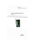
Precision Cooling
For Business-Critical Continuity
Liebert XDA™ Air Flow Enhancer
User Manual
TABLE OF CONTENTS
1.0 Product Description . . . . . . . . . . . . . . . . . . . . . . . . . . 1
1.1 Features & Benefits . . . . . . . . . . . . . . . . . . . . . . . . . . . . . . . . . . . . . 1
2.0 Installation . . . . . . . . . . . . . . . . . . . . . . . . . . . . . . . . . . 2
2.1 Equipment Inspection . . . . . . . . . . . . . . . . . . . . . . . . . . . . . . . . . . . 2
2.2 Pre-Installation Considerations . . . . . . . . . . . . . . . . . . . . . . . . . . . . 2
2.2.1 Required Tools . . . . . . . . . . . . . . . . . . . . . . . . . . . . . . . . . . . . . . . . . . . . 3
2.3 Mounting the XDA on the Exterior of the Rear Cabinet Door . . . . . 3
2.3.1 Prepare to Install the Unit . . . . . . . . . . . . . . . . . . . . . . . . . . . . . . . . . . . . 3
2.3.2 Mount the Unit and Attach it to the Cabinet . . . . . . . . . . . . . . . . . . . . . . 4
2.4 Mounting the XDA on the Interior of the Rear Cabinet Door . . . . . . 5
2.4.1 Prepare to Install the Unit . . . . . . . . . . . . . . . . . . . . . . . . . . . . . . . . . . . . 5
2.4.2 Mount the Unit and Attach It to the Cabinet . . . . . . . . . . . . . . . . . . . . . . 6
2.5 Eliminate Bypass Air . . . . . . . . . . . . . . . . . . . . . . . . . . . . . . . . . . . . 6
3.0 Power Connections. . . . . . . . . . . . . . . . . . . . . . . . . . . 7
3.1 Routing the Power Cords Through the Door - Optional. . . . . . . . . . 7
4.0 Operation & Maintenance. . . . . . . . . . . . . . . . . . . . . . 8
5.0 Specifications . . . . . . . . . . . . . . . . . . . . . . . . . . . . . . . 9
i
ii
1.0
PRODUCT DESCRIPTION
The Liebert XDA Air Flow Enhancer increases the airflow through
densely populated enclosures, breaking up hot spots within the enclosure that can threaten the uptime of your critical systems. Equipment
fans often produce insufficient flow to push air through the masses of
data communication wiring at the rear of the enclosure. With an XDA
placed on the exhaust side of the enclosure (the five high-static fans
ensure positive air flow), the heat is moved out of the enclosure and
into the room where it can be removed by the room air conditioning
system.
The Liebert XDA is also available as a factory-installed option on Liebert Foundation™ cabinets.
1.1
Features & Benefits
• Improves extraction of heat from high heat density equipment
cabinets
• Permanently attached dual power cords to prevent accidental
disconnection and increase up-time
• Hot-Installable: No shutdown or removal of rack equipment is
required
• Serves the entire cabinet
• Easily installed with common tools
• No drilling required for most installations
• Narrow enough to allow use of two units per rack for extreme
heat density situations
• Can be mounted on the outside or inside of the cabinet door
• Consumes zero “U” of rack space
• Can be used with or without a raised floor
Keep these instructions for future reference. Please take a moment to
complete the enclosed startup survey card.
!
CAUTION
Fans have moving parts that can cause personal injury.
Keep clothing and fingers away from fan openings.
System contains hazardous electrical voltage. Disconnect
BOTH power cords before working within.
Follow all local codes.
1
2.0
INSTALLATION
The Liebert XDA can be attached to most equipment cabinet doors 60"
tall or taller. The unit typically is installed on the outside of a cabinet’s rear door, generally used to discharge heat generated from the
cabinet.
If aisle space is insufficient for exterior mounting, and space is available inside the cabinet, the XDA may be installed on the inside of the
door.
2.1
Equipment Inspection
Immediately after receiving the shipment, remove the XDA and all
components from the shipping carton and inspect each item for damage. Check to see that all parts are included:
User Manual
Unit with mounting angles attached
Mounting bracket
Mounting hardware:
Screws - 10
Nuts - 10
Cable ties - 10
Blocking material
XDA as shipped - in foam packing material
Power Cord Bushing
2.2
Pre-Installation Considerations
• Verify that the XDA unit voltage matches the available utility
power. The nameplate with this information is located on the top
of the unit.
• Note the XDA’s appearance: the front of the unit bears the Liebert logo (or label) and long, horizontal slots across the fans; the
rear of the unit has smaller slots over the fans.
• The XDA is attached to the cabinet door using screws and nuts.
In most cases, existing holes in perforated cabinet doors can be
used to mount the XDA. Horizontal slots in the XDA mounting
angles provide easy alignment with existing holes in the cabinet
door.
• If the desired mounting position places mounting holes over the
solid portion of the door, mark and drill holes as needed in the
solid portion of the door, using a 3/16" drill bit.
NOTE
Check for interference with the cabinet’s handle/latch. If the
handle swings toward the center rather than toward the outside
of the door, it may limit positioning options for the XDA.
2
2.2.1 Required Tools
• Phillips screwdriver
• Pliers
• Scissors
2.3
Mounting the XDA on the Exterior of the Rear
Cabinet Door
2.3.1 Prepare to Install the Unit
1. Determine the desired mounting position on the door.
Nuts on screw
visible from
front of unit
2. Attach the mounting bracket to
the top of the XDA, positioning
the bracket to obtain the
desired mounting height.
XDA mounting
3. Position the hanging support of bracket ...
... attached to XDA
the bracket toward the rear of
the unit, with the tabs of the
bracket down and in front of the mounting angles.
4. From the rear of the unit, place screws through the XDA mounting
angles, then through the bracket.
5. Place nuts on the screws and tighten them. The nuts should be
visible from the front of the unit.
XDA with mounting bracket
being hung on door
3
Lifting mounting
bracket off XDA
2.3.2 Mount the Unit and Attach it to the Cabinet
1. Lift the unit with bracket attached and hang it on the door, as
shown at right. Ensure that the bracket rests safely on top of the
top edge of door.
2. Move the unit sideways into the desired position. Ensure that the
unit does not interfere with operation of the door latch.
3. Place screws through the middle and lower mounting holes of the
XDA mounting angle and then through the door. Place nuts on the
screws and tighten them.
4. Remove the nuts that attach the bracket to the unit and remove
the bracket.
5. Lean the top of the unit slightly away from the door and remove
the screws.
6. Install screws in the top holes in the same manner as in the middle and bottom holes. Tighten all nuts and screws.
4
2.4
Mounting the XDA on the Interior of the Rear
Cabinet Door
2.4.1
Prepare to Install the Unit
NOTE
For mounting inside the cabinet, the mounting angles must
first be reversed, as described in Steps 1 through 4 below.
1. Remove the screws on the
sides of the XDA that
secure the mounting angles
to the unit.
Wider side of mounting
angle with round holes
fits against XDA
2. Remove the mounting
angles.
3. Position the angles so their
mounting surfaces are near
the front of the XDA. (This
is the air discharge side,
Slotted
holes must
which has the Liebert logo
face mounting
and longer, horizontal slots
surface
over the fans.) To reverse
the position of the mounting
angles properly, rotate
Mounting
them vertically so that the
angles
tops of the angles are at the
attached
bottom of the XDA and the
for interior
bottoms are at the top.
mounting
4. Reattach the angles using
the screws removed in
Step 1 above.
5. Determine the desired
mounting position on the
door. Place the bracket on
the top of the door with the
tabs on the outside. (The mounting bracket will be used to determine the correct holes for screws attaching the XDA to the cabinet
door.)
6. Locate the desired mounting holes on the door for the unit.
7. From the outside of the door, place screws through the bracket,
then through the door. Place nuts on the screws and tighten them.
The nuts should now be visible on the inside surface of the door.
5
2.4.2 Mount the Unit and Attach It to the Cabinet
1. Lift the unit onto the door, placing the two mounting holes on the
top end, over the two screws attached to the door and bracket.
Place nuts on the screws to hold the unit in place.
2. On the middle and lower mounting holes, place screws through
the door and then through the mounting angle. Place nuts on the
screws. Tighten all nuts.
3. Remove the nuts from the two top screws (the ones through the
bracket and door).
4. Lean the top of the unit slightly away from the door and remove
the remaining nuts from the top two screws.
5. Pull out the top two screws and remove the bracket from the door.
6. Install the screws in the top holes in the same manner as in the
middle and bottom holes.
7. Tighten all nuts and screws.
2.5
Eliminate Bypass Air
Air that passes through the XDA but not through the heat-producing
equipment is known as bypass air. Bypass air reduces the effectiveness of your XDA, and should be eliminated. Take the following steps
to minimize bypass air and maximize heat removal from the equipment cabinet:
1. Ensure that the cable openings in the raised floor beneath the cabinet are properly sealed. Cool air from precision air conditioning
units should be provided to the inlet side of equipment in the cabinet.
2. Ensure that unused rack mounting positions are blocked off using
blanking plates. This helps ensure that air entering the cabinet
flows through the heat-producing equipment.
3. Block off the remaining open perforated area of the rear door with
the supplied material. The material provided is 10 mil thick, clear
polycarbonate plastic and has an adhesive backing. The material
is in the shipping carton, on top of the protective foam packing.
4. Ensure that the inside of the door is clean. Do not use general purpose cleaners or window cleaners—they may leave a residue that
will prevent the air-blocking material from adhering to the door.
Use plain water or rubbing alcohol.
5. Cut the material to the size necessary—it is easily cut with scissors.
6. Remove the protective paper from the adhesive side, and apply the
material to the inside surface of the door. Ensure that all open
perforations are covered.
6
3.0
POWER CONNECTIONS
Connect the power cords to separate power sources (as specified in
Specifications on page 9), to keep the XDA operating if there is a
power failure on one circuit. Route the power cords under or over the
cabinet as needed to the nearest available receptacles. If only one
power source is available, connect both power cords to this source.
Separate electrical circuits are recommended. Ensure adequate length
of the power cords when the door is fully opened. Secure the power
cords using the cable ties provided.
3.1
Routing the Power Cords Through the Door Optional
The power cords may be routed through an additional hole cut in the
cabinet door. Special tools are required for this.
1. At a point several inches below the unit and centered between the
two power cords, cut or punch a 2-inch diameter hole in the door.
2. Install the 2-inch plastic power cord bushing to protect the power
cords from damage.
3. Route the power cords through the cabinet to the desired connection points.
7
4.0
OPERATION & MAINTENANCE
The XDA is activated by turning on the
ON/OFF switch on the bottom of the
unit, near the power cords. All fans
operate continuously to remove the
maximum amount of heat from the cabinet.
If a power failure should occur on the
primary power source, the XDA will
operate from the secondary source until
the primary power source is restored.
ON/OFF switch
(seen from below the XDA)
The XDA will continue to operate as
long as either of the two power sources is available.
The Liebert XDA is essentially maintenance-free. An occasional vacuuming at the same time other cabinet equipment is cleaned is adequate.
8
5.0
SPECIFICATIONS
Nominal Capacity
1000 CFM @ 60Hz
Dimensions
W x D x H, in (mm)
8 x 2.25 x 56
(203.2 x 57.2 x 1422.4)
Weight, lbs (kg)
25 (11.3)
120V-1-50/60Hz
230V-1-50/60Hz
Electrical Specifications
1.5 A @ 120V
0.8 A @ 230V
Amp Draw
9
10
Ensuring The High Availability
0f Mission-Critical Data And Applications.
Locations
Technical Support / Service
Web Site
www.liebert.com
Monitoring
800-222-5877
[email protected]
Outside the US: 614-841-6755
Single-Phase UPS
800-222-5877
[email protected]
Outside the US: 614-841-6755
Three-Phase UPS
800-543-2378
[email protected]
Environmental Systems
800-543-2778
Outside the United States
614-888-0246
United States
1050 Dearborn Drive
P.O. Box 29186
Columbus, OH 43229
Europe
Via Leonardo Da Vinci 8
Zona Industriale Tognana
35028 Piove Di Sacco (PD) Italy
+39 049 9719 111
Fax: +39 049 5841 257
Asia
7/F, Dah Sing Financial Centre
108 Gloucester Road, Wanchai
Hong Kong
852 2572220
Fax: 852 28029250
While every precaution has been taken to ensure the accuracy and completeness of this literature, Liebert Corporation assumes
no responsibility and disclaims all liability for damages resulting from use of this information or for any errors or omissions.
© 2006 Liebert Corporation
All rights reserved throughout the world.
Specifications subject to change without notice.
® Liebert and the Liebert logo are registered trademarks of Liebert Corporation. All names referred to are trademarks or
registered trademarks of their respective owners.
SL-16610_REV2_08-06
Emerson Network Power.
The global leader in enabling Business-Critical Continuity™.
EmersonNetworkPower.com
AC Power Systems
Outside Plant
Connectivity
Power Switching & Control
DC Power Systems
Precision Cooling
Embedded Computing
Services
Embedded Power
Site Monitoring
Integrated Cabinet Solutions
Surge Protection
Business-Critical Continuity, Emerson Network Power and the Emerson Network Power logo are
trademarks and service marks of Emerson Electric Co.
©2006 Emerson Electric Co.