1
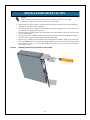
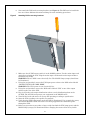
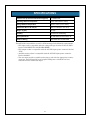
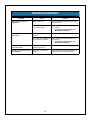
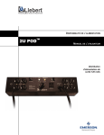
POWER AVAILABILITY
2U POD™
USER MANUAL
Power Output
Distribution
230 Volt
TABLE OF CONTENTS
IMPORTANT SAFETY INSTRUCTIONS . . . . . . . . . . . . . . . . . . . . . . . . . . . . . . . . . . . . . . . . . . 1
GLOSSARY OF SYMBOLS . . . . . . . . . . . . . . . . . . . . . . . . . . . . . . . . . . . . . . . . . . . . . . . . . . 2
INTRODUCTION AND SYSTEM DESCRIPTION . . . . . . . . . . . . . . . . . . . . . . . . . . . . . . . . . . . . . 3
System Description . . . . . . . . . . . . . . . . . . . . . . . . . . . . . . . . . . . . . . . . . . . . . . . . . . . . . . . 3
INSTALLATION ON GXT 2U UPS . . . . . . . . . . . . . . . . . . . . . . . . . . . . . . . . . . . . . . . . . . . . 4
RACK MOUNT INSTALLATION . . . . . . . . . . . . . . . . . . . . . . . . . . . . . . . . . . . . . . . . . . . . . . . 6
INDICATOR LAMPS . . . . . . . . . . . . . . . . . . . . . . . . . . . . . . . . . . . . . . . . . . . . . . . . . . . . . . . 7
MAINS Indicator Lamp. . . . . . . . . . . . . . . . . . . . . . . . . . . . . . . . . . . . . . . . . . . . . . . . . . . . . 7
UPS Indicator Lamp. . . . . . . . . . . . . . . . . . . . . . . . . . . . . . . . . . . . . . . . . . . . . . . . . . . . . . . 7
OPERATION . . . . . . . . . . . . . . . . . . . . . . . . . . . . . . . . . . . . . . . . . . . . . . . . . . . . . . . . . . . . 8
Transfer to Maintenance Bypass . . . . . . . . . . . . . . . . . . . . . . . . . . . . . . . . . . . . . . . . . . . . 8
Transfer to UPS . . . . . . . . . . . . . . . . . . . . . . . . . . . . . . . . . . . . . . . . . . . . . . . . . . . . . . . . . . 8
SPECIFICATIONS . . . . . . . . . . . . . . . . . . . . . . . . . . . . . . . . . . . . . . . . . . . . . . . . . . . . . . . . 9
TROUBLESHOOTING . . . . . . . . . . . . . . . . . . . . . . . . . . . . . . . . . . . . . . . . . . . . . . . . . . . . . 10
FIGURES
Figure 1
Figure 2
Figure 3
Figure 4
Figure 5
Figure 6
Figure 7
UPS mode of operation . . . . . . . . . . . . . . . . . . . . . . . . . . . . . . . . . . . . . . . . . . . . . . . . . . . . . .
MAINS/maintenance bypass mode . . . . . . . . . . . . . . . . . . . . . . . . . . . . . . . . . . . . . . . . . . .
2U POD connections. . . . . . . . . . . . . . . . . . . . . . . . . . . . . . . . . . . . . . . . . . . . . . . . . . . . . . . .
Attaching POD securing brackets to rear of UPS . . . . . . . . . . . . . . . . . . . . . . . . . . . . . . . .
Attaching POD to securing brackets . . . . . . . . . . . . . . . . . . . . . . . . . . . . . . . . . . . . . . . . . .
2U POD with rack mounting brackets . . . . . . . . . . . . . . . . . . . . . . . . . . . . . . . . . . . . . . . . .
Indicator lamps on 2U POD . . . . . . . . . . . . . . . . . . . . . . . . . . . . . . . . . . . . . . . . . . . . . . . . . .
i
3
3
3
4
4
6
7
IMPORTANT SAFETY INSTRUCTIONS
!
WARNING
DO NOT ATTEMPT TO SERVICE THIS PRODUCT YOURSELF. OPENING OR
REMOVING THE COVER MAY EXPOSE YOU TO DANGEROUS VOLTAGES,
EVEN WHEN THE AC CORD IS DISCONNECTED FROM THE ELECTRICAL
SOCKET. REFER ALL SERVICING TO QUALIFIED SERVICE PERSONNEL.
SAVE THESE INSTRUCTIONS
This manual contains important instructions that should be followed during installation and
operation of the 2U POD™.
This product is designed for commercial / industrial use only, with Liebert UPS systems. It is
not intended for use with life support and other designated “critical” devices. Do not exceed
POD or UPS rating labels.
Read all safety and operating instructions before operating the 2U POD™ and the connected
UPS system. Adhere to all warnings on the unit and in this manual. Follow all operating and
user instructions.
Turn the UPS off and unplug the 2U POD™ before cleaning. Use only a soft cloth, never liquid
or aerosol cleaners.
The UPS and 2U POD™ are designed for data processing equipment. Do not plug laser printers or appliances, such as hair dryers, heaters, vacuum cleaners, or electric drills, into the UPS
output sockets.
!
WARNING
DO NOT MODIFY THE CABLES IN ANY WAY. THE POD SOCKETS SHOULD
MATCH THE UPS SOCKETS. CONSULT YOUR DEALER IF THE AC CORDS
DO NOT MATCH THE MAINS SOCKET. THE 2U POD™ MUST BE EARTHED
AT ALL TIMES WHILE IN USE. TURN OFF THE UPS BEFORE
UNPLUGGING IT.
The UPS and the 2U POD™ are equipped with earthed plugs (plug types vary depending on
model). Do not defeat the safety purpose of this plug. If unable to fully insert the plug into the
designated socket, contact a qualified electrician or your local dealer or Liebert representative
for assistance.
Route power supply cords so they are not walked on or pinched in anyway.
!
!
!
!
CAUTION
Risk of electric shock, do not remove cover, no user serviceable parts inside.
Refer servicing to qualified service personnel.
CAUTION
This device receives power from multiple sources. Before servicing this
device, remove all connections. Before servicing the UPS, follow
“Maintenance of UPS” instructions in the user manual for your UPS.
CAUTION
For use in a controlled environment. Refer to manual specifications for
environmental conditions.
WARNING
WHEN THE 2U POD™ IS IN MAINS POSITION (MAINTENANCE BYPASS
MODE) THE POWER TO THE CONNECTED LOAD IS NOT FILTERED OR
CONDITIONED BY THE UPS. THE LIEBERT UPS CONNECTED EQUIPMENT
GUARANTEE IS NOT VALID WHILE IN THIS MODE OF OPERATION.
1
GLOSSARY OF SYMBOLS
•
Indicates AC Input.
Indicates AC Output.
i
MAINS
UPS
Consult the manual for additional information.
MAINS lamp indicates local power is available and the load may be
transferred to bypass the UPS.
UPS lamp indicates UPS power is available and the load may be
transferred to the UPS to provide computer-grade power to the load.
2
INTRODUCTION AND SYSTEM DESCRIPTION
Congratulations on your choice of the Liebert 2U POD™. The Liebert 2U POD provides maintenance bypass capability as well as power output distribution. The Liebert 2U POD can be
used on UPSs in the rack mount or tower configuration.
The Liebert 2U POD provides an isolated path of power for your UPS system for preventive
maintenance or service.
System Description
The 2U POD has two modes of operation: UPS (UPS available) and MAINS (maintenance
bypass).
• In UPS mode, the power is routed through the UPS system delivering conditioned power
to the load, as shown in Figure 1.
Figure 1
UPS mode of operation
POD
Mains
Connected
loads
UPS
• In MAINS mode, the power is routed around (bypassing) the UPS system (see Figure 2).
Mains power is supplied directly to the load through the 2U POD.
CAUTION
Battery back-up and conditioned power are NOT available
during the MAINS mode of operation.
!
Figure 2
MAINS/maintenance bypass mode
POD
Mains
Connected
loads
UPS
• The UPS may be turned off and removed without affecting the load. See Figure 3.
Figure 3
2U POD connections
UPS INPUT
Connect to load socket on
rear of UPS. Cable supplied.
Rotary switch
and power
indicator lamps.
UPS
AVAILABLE
10A
A
MAINS INPUT
Connect to mains wall socket. Use
original UPS mains input cord.
MAINTENANCE BYPASS
AVAILABLE
CIRCUIT BREAKER
10A
B
16A 250V-/T
UPS
MAINS
10A
CONNECT UPS LINE CORD HERE
CAUTION
IF MAINS LAMP IS ILLUMINATED
MAINTENANCE BYPASS POSITION
MAY BE SELECTED.
SWITCH TO UPS POSITION ONLY
WHEN UPS LAMP IS ILLUMINATED.
UPS
MAINS
A+B MAX. 16A
Connect UPS
input cord here.
Cable supplied.
Connect loads.
3
Connect loads.
INSTALLATION ON GXT 2U UPS
NOTE
This manual provides instructions for the 2U POD only. Refer to your UPS
manual for UPS operation and installation instructions.
1. Unpack the 2U POD carefully, noting the packing method. Retain the box and packing
material for possible future shipments.
2. Visually inspect the 2U POD for freight damage. Report damage to the carrier and your
local dealer or Liebert representative.
3. Verify that the 2U POD input cord, UPS input cord, and socket for the UPS are the same
type of configuration.
4. If you already have a UPS installed, turn off all connected loads and unplug them from
the UPS. Turn off the UPS and disconnect the input cord.
5. Attach the two POD securing brackets (this is optional for GXT 2U UPS) to the rear of the
UPS (see Figure 4). You will need a long M3 Phillips head screwdriver for this procedure
(the torque is 0.79 Nm, or 7 in-lb). The POD brackets have a hole to allow the screwdriver
to reach the screw.
Figure 4
Attaching POD securing brackets to rear of UPS
4
6. Next attach the POD to the securing brackets (see Figure 5). The POD can be installed to
face one of three different directions utilizing the same mounting procedures.
Figure 5
Attaching POD to securing brackets
7. Make sure the 2U POD rotary switch is in the MAINS position. Use the mains input cord
originally used with the UPS. Plug the mains input cord from the mains input socket to
the mains wall socket.
WARNING: The 2U POD is now electrically live. The MAINS lamp (orange) should now
be illuminated.
8. Using the cord provided, connect the UPS input power socket to the POD socket labeled
“CONNECT UPS LINE CORD HERE.”
WARNING: The UPS system is now electrically live.
9. Using the cord provided, connect the POD socket labeled “UPS” to one of the output
sockets on the rear of the UPS.
10. Plug in all loads to the output distribution sockets, evenly distributing them on the
2U POD. The 2U POD now powers your equipment in the MAINS mode.
11. Turn ON the loads and ensure all are up and operating according to specification.
12. Start the UPS according to its specific user manual.
13. Verify that the UPS lamp (green) on the 2U POD is illuminated. If so, transfer the rotary
switch from MAINS to UPS. The load is now being supplied with conditioned power
through the UPS.
14. Before any operation or procedure, always verify that both the UPS lamp (green) and the
MAINS lamp (orange) are illuminated before changing the status of the rotary switch.
5
RACK MOUNT INSTALLATION
1. Rack mount installation of the 2U POD is possible with the use of the rack mounting
brackets (shipped with the POD). See Figure 6.
2. The rack mount brackets allow you to rack mount the POD in a 19" enclosure (23" to 19"
rack adapters would have to purchased separately if you are using our 23" Foundation or
equivalent cabinet).
3. The POD can be mounted to face one of four directions depending on your application, and
utilizing the rack mount brackets provided.
4. Determine the desired position and direction for the POD, face it in that direction, then
attach the brackets to the POD with the screws provided.
5. Consult your rack/enclosure manufacturer’s recommendations for specific rack mounting
hardware that will be required.
6. The holes on the rack mount bracket are notched for easy installation. Tighten the POD
securely to the rails and then follow the startup directions for the POD in the previous
section, Installation on GXT 2U UPS.
Figure 6
2U POD with rack mounting brackets
UPS
AVAILABLE
10A
A
MAINTENANCE BYPASS
AVAILABLE
CIRCUIT BREAKER
10A
B
16A 250V-/T
UPS
MAINS
CONNECT UPS LINE CORD HERE
CAUTION
IF MAINS LAMP IS ILLUMINATED
MAINTENANCE BYPASS POSITION
MAY BE SELECTED.
UPS
SWITCH TO UPS POSITION ONLY
WHEN UPS LAMP IS ILLUMINATED.
MAINS
A+B MAX. 16A
Rack mounting brackets
6
10A
INDICATOR LAMPS
MAINS Indicator Lamp
This orange lamp is illuminated when mains power is present (see Figure 7). It signals that
you may transfer the loads to maintenance bypass (MAINS mode) operation via the rotary
switch. During a mains power outage, this lamp will be off and the UPS will supply battery
back-up power to the connected loads.
UPS Indicator Lamp
This green lamp is illuminated when there is output power available from the UPS (see
Figure 7). It signals that it is safe to transfer the connected loads from mains power back to
UPS output power.
Figure 7
Indicator lamps on 2U POD
Green lamp:
Output power available from UPS
UPS
AVAILABLE
Orange lamp:
MAINS power present
MAINTENANCE BYPASS
AVAILABLE
CIRCUIT BREAKER
16A 250V-/T
UPS
MAINS
CONNECT UPS LINE CORD HERE
Rotary
switch
7
OPERATION
Transfer to Maintenance Bypass
To transfer to maintenance bypass (mains) from UPS, use the following steps:
1. Ensure the MAINS lamp (orange) is illuminated. If the lamp is not illuminated, refer to
Troubleshooting section.
2. Transfer the rotary switch from UPS to MAINS, provided the MAINS lamp is illuminated
on the 2U POD.
3. Turn the UPS off.
4. Disconnect the two cables connecting the UPS to the 2U POD.
5. You may now service the UPS.
Transfer to UPS
To transfer to UPS from maintenance bypass (mains), use the following steps:
1. Reconnect the UPS to the 2U POD. Start the UPS according to the instructions in the
UPS user manual.
2. Verify that UPS lamp (green) on the 2U POD is illuminated. If so, transfer the rotary
bypass switch from MAINS to UPS. If the lamp does not illuminate, refer to
Troubleshooting section.
3. Conditioned power is now being supplied through the UPS.
8
SPECIFICATIONS
Transfer Time (to and from maintenance bypass)
< 6 milliseconds
Operating Ambient Temperature
0°C to +40°C (32°F to 104°F)
Storage Ambient Temperature
-20°C to +60°C (-4°F to 140°F)
Dimensions W x D x H: mm (in.)
88 x 77 x 394 (3.5 x 3.0 x 15.5)
Weight: kg (lbs)
4.5 (10)
Humidity
0 to 95% non-condensing
Agency/Standards
CE, EN 60950, ISTA Procedure 1A
Electrical Rating
See Model Label on MicroPOD
This 2U POD is intended for use with a UPS meeting all the following requirements:
• UPS input cord is compatible with the rating and type of socket on the 2U POD
labeled “CONNECT UPS LINE CORD HERE.”
• UPS output socket is compatible with the 2U POD input power connector labeled
“UPS.”
• Available mains socket is compatible with the 2U POD input power connector
labeled “MAINS.”
• The user must provide a suitable mains power cord with the appropriate country
connector. This will usually be the original UPS power cord which has been
removed from the UPS mains input.
9
TROUBLESHOOTING
Problem
MAINS lamp (orange) not
illuminated.
Cause
Solution
Mains not present.
Call qualified service personnel to restore
power to socket.
2U POD input cord not
connected to mains.
Refer to 2U POD installation instructions in
this manual:
• Installation on GXT 2U UPS and
• Rack Mount Installation.
UPS output power not
present.
Turn on UPS. Refer to UPS user manual.
UPS input and/or output cord
not connected to 2U POD.
Refer to 2U POD installation instructions in
this manual:
• Installation on GXT 2U UPS and
• Rack Mount Installation.
2U POD will not start some / all
connected loads.
2U POD output circuit
breaker has tripped.
Reset 2U POD circuit protectors.
2U POD circuit protectors trip
after resetting.
Overcurrent on 2U POD
socket.
Recalculate load requirements, distribute
load among other 2U POD sockets.
UPS Available lamp (green) not
illuminated.
10
POWER AVAILABILITY
2U POD™
USER MANUAL
The Company Behind the Products
Technical Support
With over a million installations around the globe,
Liebert is the world leader in computer protection
systems. Since its founding in 1965, Liebert has
developed a complete range of support and
protection systems for sensitive electronics:
United States
1050 Dearborn Drive
P.O. Box 29186
Columbus, OH 43229
•
•
•
•
•
Environmental systems—close-control air
conditioning from 1 to 60 tons
Power conditioning and UPS with power
ranges from 300 VA to more than 1000 kVA
Integrated systems that provide both
environmental and power protection in a
single, flexible package
Monitoring and control—from systems of any
size or location, on-site or remote
Service and support through more than 100
service centers around the world and a 24/7
Customer Response Center
While every precaution has been taken to ensure
the accuracy and completeness of this literature,
Liebert Corporation assumes no responsibility and
disclaims all liability for damages resulting from
use of this information or for any errors or
omissions.
© 2002 Liebert Corporation
All rights reserved throughout the world.
Specifications subject to change without notice.
® Liebert and the Liebert logo are registered
trademarks of Liebert Corporation. All names
referred to are trademarks or registered
trademarks of their respective owners.
SLI-23153 (5/02)
Single-Phase UPS
800-222-5877
Outside the United States
614-841-6755
3-Phase UPS
800-543-2378
Environmental Control
800-543-2778
Italy
Via Leonardo Da Vinci 8
Zona Industriale Tognana
35028 Piove Di Sacco (PD)
+39 049 9719 111
FAX: +39 049 5841 257
Asia
23F, Allied Kajima Bldg.
138 Gloucester Road
Wanchai
Hong Kong
+852 2 572 2201
FAX: +852 2 831 0114
Web Site
www.liebert.com
E-mail
[email protected]