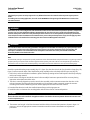
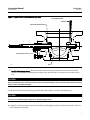
1
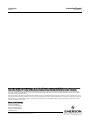
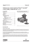
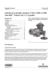
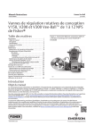
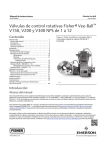
Instruction Manual
V150E Valve
D103435X012
April 2012
Fisherr V150E Expanded Outlet Vee-Ball™
Control Valve
Contents
Introduction . . . . . . . . . . . . . . . . . . . . . . . . . . . . . . . . . 1
Scope of Manual . . . . . . . . . . . . . . . . . . . . . . . . . . . . . 1
Description . . . . . . . . . . . . . . . . . . . . . . . . . . . . . . . . . 1
Specifications . . . . . . . . . . . . . . . . . . . . . . . . . . . . . . . 2
Installation . . . . . . . . . . . . . . . . . . . . . . . . . . . . . . . . . . . . 2
Maintenance . . . . . . . . . . . . . . . . . . . . . . . . . . . . . . . . . . 5
Packing Maintenance . . . . . . . . . . . . . . . . . . . . . . . . 5
Replacing the HD Ball Seal . . . . . . . . . . . . . . . . . . . . . 7
Bearing and Ball Maintenance . . . . . . . . . . . . . . . . . 12
Actuator Mounting . . . . . . . . . . . . . . . . . . . . . . . . . . . . 15
Determining Mounting Position . . . . . . . . . . . . . . . 16
Determining Closed Position . . . . . . . . . . . . . . . . . 16
Parts Ordering . . . . . . . . . . . . . . . . . . . . . . . . . . . . . . . . 16
Parts Kits . . . . . . . . . . . . . . . . . . . . . . . . . . . . . . . . . . . . . 21
Parts List . . . . . . . . . . . . . . . . . . . . . . . . . . . . . . . . . . . . . 22
Figure 1. Fisher V150E Expanded Outlet Vee-Ball
Valve with 2052 Actuator and FIELDVUE™ DVC6200
Digital Valve Controller
W9915
Introduction
Scope of Manual
This instruction manual provides installation, operation, maintenance, and parts information for the Fisher Vee-Ball
V150E rotary control valve (see figure 1).
For information on ENVIRO-SEAL™ packing, see the ENVIRO-SEAL Packing System for Rotary Valves instruction
manual, D101643X012. Refer to separate manuals for information concerning the actuator, positioner and
accessories.
Do not install, operate, or maintain a V150E valve without being fully trained and qualified in valve, actuator, and
accessory installation, operation, and maintenance. To avoid personal injury or property damage, it is important to
carefully read, understand, and follow all the contents of this manual, including all safety cautions and warnings. If you
have any questions about these instructions, contact your Emerson Process Management sales office before
proceeding.
Description
V150E Vee-Ball valves (figure 1) with a V-notch ball are used in throttling service. The V150E valve is a raised-face
flanged construction. The splined valve shaft connects to a variety of Fisher rotary-shaft actuators.
www.Fisher.com
Instruction Manual
V150E Valve
April 2012
D103435X012
Table 1. Specifications
Actuator Mounting
Valve Sizes and End Connection Styles
DN J 80x100, J 100x150, J 150x200, J 200x250,
J 250x300 and NPS J 3x4, J 4x6, J 6x8, J 8x10,
J 10x12 flanged valves that mate with J PN 10/16,
J JIS 10K, or J CL150 raised-face flanges (see table
2)
Dimensions
See table 6 for dimensions
Standard valve construction is for right-hand
mounting, as viewed from upstream end of valve with
the shaft horizontal. Actuator can be mounted in any
of four quadrants. Left-hand actuator mounting is
available upon request
Valve/Actuator Action
Standard Flow Direction
Forward (into the convex face of the V-notch ball)
Maximum Ball Rotation
90 degrees
Orientation
Valve shaft must be horizontal when installed in a
horizontal or vertical pipeline
With compact 2052 spring and diaphragm or Fisher
1061 piston rotary actuator, the valve is
field-reversible between PDTC or PDTO:
push-down-to-close (extending actuator rod closes
valve) and push-down-to-open (extending actuator
rod opens valve)
Approximate Weight
See table 6
1. The pressure/temperature limits in this manual and any applicable standard or code limitation for valve should not be exceeded.
Table 2. Valve Body Material, End Connections, and Ratings
VALVE DESIGN
V150E
VALVE BODY MATERIAL
CG8M
VALVE SIZE
FLANGE END CONNECTIONS
DN 80x100, 100x150, 150x200,
200x250, 250x300
Compatible with PN 10/16 or
JIS 10K raised-face flanges
NPS 3x4, 4x6, 6x8, 8x10, 10x12
Compatible with CL150
raised-face flanges
Specifications
Specifications for these valves are shown in table 1 and in bulletin 51.3:V150E, D103429X012.
Installation
Installation steps are provided in this section for V150E valves. Key numbers in installation procedures are shown in
figure 10 unless otherwise indicated.
WARNING
Always wear protective gloves, clothing, and eyewear when performing any installation operations to avoid personal
injury.
Personal injury or equipment damage caused by sudden release of pressure may result if the valve assembly is installed
where service conditions could exceed either the valve body rating or the mating pipe flange joint rating. To avoid such
injury or damage, provide a relief valve for overpressure protection as required by government or accepted industry codes
and good engineering practices.
2
Instruction Manual
D103435X012
V150E Valve
April 2012
Check with your process or safety engineer for any additional measures that must be taken to protect against process
media.
If installing into an existing application, also refer to the WARNING at the beginning of the Maintenance section in this
instruction manual.
WARNING
When ordered, the valve configuration and construction materials were selected to meet particular pressure, temperature,
pressure drop, and controlled fluid conditions. Responsibility for the safety of process media and compatibility of valve
materials with process media rests solely with the purchaser and end-user. To avoid possible personal injury and because
some valve/trim material combinations are limited in their pressure drop and temperature ranges, do not apply any other
conditions to the valve without first contacting your Emerson Process Management sales office.
WARNING
The valve drive shaft is not necessarily grounded to the pipeline when installed. Personal injury or property damage could
result from an explosion caused by a discharge of static electricity from valve components if the process fluid or the
atmosphere around the valve is flammable. If the atmosphere around the valve or the process fluid is flammable,
electrically bond the drive shaft to the valve.
Note
Standard PTFE packing is composed of a partially conductive carbon-filled PTFE female adaptor with PTFE V-ring packing. Standard
graphite packing is composed of all conductive graphite ribbon packing. Alternate shaft-to-valve body bonding is available for
hazardous service areas where the standard packing is not sufficient to bond the shaft to the valve (see the following step).
Attach the optional bonding strap assembly (key 131, figure 2) to the valve drive shaft (key 6) with the clamp (key 130,
figure 2) and connect the other end of the bonding strap assembly to the valve body with the cap screw (key 23).
1. If the valve is to be stored before installation, protect the flange mating surfaces and keep the valve body cavity dry
and free of foreign material.
2. Install a three-valve bypass around the control valve assembly if continuous operation will be necessary during
inspection and maintenance of the valve.
3. The valve is normally shipped as part of a control valve assembly, with an actuator mounted on the valve. If the
valve and actuator have been purchased separately or if the actuator has been removed, mount the actuator
according to the Actuator Mounting section and the appropriate actuator instruction manual.
4. Standard flow direction is with the smaller diameter flange end facing upstream.
5. Install the valve in a horizontal or vertical pipeline with the drive shaft in a horizontal position.
CAUTION
Do not allow the valve to be installed in the pipeline with the drive shaft in the vertical position because of excessive wear
to valve component parts.
6. The actuator can be right- or left-hand mounted with the shaft in a horizontal orientation as shown in figure 1. If
necessary, refer to the appropriate actuator instruction manual for actuator installation and adjustment
procedures.
3
Instruction Manual
V150E Valve
April 2012
D103435X012
CAUTION
Ensure the valve and adjacent pipelines are free of foreign material that could damage the valve seating surfaces.
7. Be certain the valve and adjacent pipelines are free of any foreign material that could damage the valve sealing
surfaces.
8. Be sure the pipeline flanges are in line with each other.
Figure 2. Optional Shaft-to-Body Bonding Strap Assembly
VALVE
BODY
37A6528-A
A3143-2
ACTUATOR
A
VIEW A-A
A
Installing V150E Valves
1. Install the V150E valve using standard length flange studs and nuts, appropriate for the inlet and outlet ends of the
valve as dictated by the size and rating of the flange, to connect the valve flanges to the pipeline flanges.
2. Lubricate the studs with anti-seize lubricant.
3. Insert flat-sheet line flange gaskets (or spiral-wound gaskets with compression-controlling center rings) that are
compatible with the flowing media.
4. Connect pressure lines to the actuator as indicated in the actuator instruction manual. When an auxiliary manual
actuator is used with a power actuator, install a bypass valve on the power actuator (if one is not supplied) for use
during manual operation.
WARNING
Personal injury could result from packing leakage. Valve packing was tightened before shipment; however the packing
might require some readjustment to meet specific service conditions. Check with your process or safety engineer for any
additional measures that must be taken to protect against process media.
If the valve has ENVIRO-SEAL live-loaded packing installed, this initial re-adjustment will probably not be required. See
ENVIRO-SEAL Packing System for Rotary Valves instruction manual, D101643X012, for packing instructions.
4
Instruction Manual
V150E Valve
D103435X012
April 2012
Maintenance
Valve parts are subject to normal wear and must be inspected and replaced as necessary. The frequency of inspection
and replacement depends upon the severity of service conditions.
Key numbers in this procedure are shown in figure 10, unless otherwise noted.
WARNING
The Vee-ball closes with a shearing, cutting motion, which could result in personal injury. To avoid injury, keep hands,
tools, and other objects away from the Vee-ball while stroking the valve.
Avoid personal injury from sudden release of process pressure. Before performing any maintenance operations:
D Do not remove the actuator from the valve while the valve is still pressurized.
D Disconnect any operating lines providing air pressure, electric power, or a control signal to the actuator. Be sure the
actuator cannot suddenly open or close the valve.
D Use bypass valves or completely shut off the process to isolate the valve from process pressure. Relieve process pressure
from both sides of the valve. Drain the process media from both sides of the valve.
D Vent the power actuator loading pressure and relieve any actuator spring precompression.
D Use lock-out procedures to be sure that the above measures stay in effect while you work on the equipment.
D Always wear protective gloves, clothing, and eyewear when performing any maintenance operations.
D The valve packing area may contain process fluids that are pressurized, even when the valve has been removed from the
pipeline. Process fluids may spray out under pressure when removing the packing hardware or packing rings.
D Check with your process or safety engineer for any additional measures that must be taken to protect against process
media.
Packing Maintenance
Key numbers in this procedure are shown in figure 10, unless otherwise noted. A detailed view of the packing is also
shown in figure 3.
If the valve is equipped with the ENVIRO-SEAL Packing System, refer to:
D the separate ENVIRO-SEAL Packing System for Rotary Valves instruction manual, D101643X012, for maintenance
instructions, and
D the Parts List section of this manual for retrofit kits, parts kits, and individual parts.
If the packing is relatively new and tight on the drive shaft (key 6), and if tightening the packing follower nuts does not
stop leakage, it is possible that the drive shaft is worn or nicked so that a seal cannot be made. If the leakage comes
from the outside diameter of the packing, it is possible that the leakage is caused by nicks or scratches on the packing
box wall. Inspect the drive shaft and packing box wall for nicks or scratches while performing the following procedure.
Replacing Packing
When using this procedure, it is recommended that the actuator not be removed from the valve while the valve is still
in the pipeline or between flanges. Valve/actuator adjustments must be made with the valve out of the pipeline. Refer
to the Determining Closed Position portion of the Actuator Mounting section.
5
V150E Valve
April 2012
Instruction Manual
D103435X012
Disassembly
WARNING
Observe the steps in the WARNING at the beginning of the Maintenance section.
1. Isolate the control valve from the line pressure, release pressure from both sides of the valve body, and drain the
process media from both sides of the valve. If using a power actuator, shut off all pressure lines to the power
actuator, release pressure from the actuator, and disconnect the pressure lines from the actuator. Use lock-out
procedures to be sure that the above measures stay in effect while you are working on the equipment.
2. Remove line bolting, remove the control valve from the pipeline, and place the valve/actuator assembly on a flat
surface with the inlet facing up.
3. Remove the actuator cover. Take note of the orientation of the actuator with respect to the valve body and the
lever orientation with respect to the valve drive shaft (see figure 9).
WARNING
When the actuator is removed from the valve, the ball/shaft assembly may suddenly rotate, with a shearing, cutting
motion, which could result in personal injury. To avoid injury, carefully rotate the ball to a stable position after the actuator
is removed.
CAUTION
When removing the actuator from the valve, do not use a hammer or similar tool to drive the lever or actuator off the valve
shaft. Driving the lever or actuator off the valve shaft could damage the ball, seal, and valve.
If necessary, use a puller to remove the lever or actuator from the valve shaft. It is okay to tap the puller screw lightly to
loosen lever or actuator, but hitting the screw with excessive force could damage the ball, seal, and valve.
4. Loosen the clamped lever, remove the actuator mounting screws and nuts (keys 23 and 24), and remove the
actuator. (If necessary, refer to the actuator instruction manual for assistance.)
5. If applicable, remove the bonding strap assembly before attempting to remove the packing (see figure 2).
6. Remove the packing follower nuts and packing follower (keys 17 and 20). For alloy packing constructions, the
packing follower (key 17) and a separate packing flange (key 40) must be removed if present.
If the valve is equipped with the ENVIRO-SEAL packing system, refer to the ENVIRO-SEAL Packing System for Rotary
Valves instruction manual, D101643X012, for disassembly.
WARNING
Personal injury could result from packing leakage. Do not scratch the drive shaft or packing box wall while removing
packing parts in the following procedure.
7. Remove the packing parts (see figure 3, keys 16, 17, 35, and 39 depending on construction) using a formed wire
hook with a sharp end. Pierce the rings with the sharp end of the hook in order to remove them. Do not scratch the
6
Instruction Manual
D103435X012
V150E Valve
April 2012
drive shaft or packing box wall; scratching these surfaces could cause leakage. Clean all accessible metal parts and
surfaces to remove particles that would prevent the packing from sealing.
Assembly
If the valve is equipped with the ENVIRO-SEAL packing system, refer to the ENVIRO-SEAL Packing System for Rotary
Valves instruction manual, D101643X012, for assembly.
1. To help ensure correct centering of the Vee-ball (key 2) on the seal (key 11), make sure the ball is closed while you
install or tighten new packing. Insert a screwdriver, pry bar, or similar tool between the lower ear of the ball and the
valve body. Use the pry to move the ball tightly against the bearing on the actuator side of the valve (see figure 4).
Keep the ball in that position until you have completed packing installation and adjustment.
2. Install the new packing parts using the parts sequence shown in figure 3. Install the packing follower (key 17).
3. Secure the packing follower with the packing follower nuts (key 20). Tighten the nuts far enough to stop leakage
under operating conditions.
Note
If the valve is equipped with a bonding strap assembly (figure 2), re-install the assembly.
4. Reconnect the actuator and lever in accordance with the orientations that were noted in step 3 of the disassembly
procedures. If necessary, use figure 9 to identify the correct index marks.
5. Refer to the appropriate actuator instruction manual to complete actuator assembly and adjustment.
6. When the control valve is in operation, check the packing follower for leakage and retighten the packing follower
nuts (key 20) as necessary.
Replacing the HD Ball Seal
Perform this procedure if the control valve is not shutting off properly or if seal inspection or replacement is necessary.
The valve / actuator assembly must be removed from the pipeline and the actuator must be removed from the valve to
replace the ball seal. Key numbers are shown in figure 13 unless otherwise indicated. Ball Seal assembly details (with
key numbers) are also shown in figure 5.
WARNING
Perform the steps in the WARNING at the beginning of the Maintenance section of this manual.
Removing the HD seal
1. Remove line bolting, remove the control valve from the pipeline, remove the actuator (as discussed in the packing
section), and place the valve body on a flat work surface.
a. For NPS 3x4 and 4x6 valves, the ball must be removed to access the seal. See the Bearing and Ball Maintenance
Disassembly section on page 12 in this manual. Then return to this procedure and continue with the next steps.
7
Instruction Manual
V150E Valve
April 2012
D103435X012
Figure 3. Packing Arrangements
PACKING FOLLOWER (KEY 17)
PACKING FOLLOWER (KEY 17)
PACKING RING
(KEY 35)
PACKING SET
(KEY 16)
1
PACKING
BOX RING (KEY 39)
PACKING
BOX RING (KEY 39)
PTFE V-RING PACKING
FOR V150E
NOTE:
INCLUDES ZINC WASHERS (KEY 36) FOR
1
GRAPHITE RIBBON PACKING ONLY.
28B5170
GRAPHITE RIBBON PACKING
FOR V150E
STANDARD PACKING
PACKING FLANGE
(KEY 102)
PACKING FLANGE
NUT (KEY 101)
SPRING PACK
ASSEMBLY
(KEY 103)
LUBRICANT
(KEY 113)
ANTI-EXTRUSION
RING (KEY 106)
PACKING FLANGE
STUD (KEY 100)
PACKING BOX
RING (KEY 107)
PACKING SET
(KEY 105)
42B8445-C
ENVIRO-SEAL PTFE PACKING SYSTEM
PACKING FLANGE
NUT (KEY 101)
PACKING FLANGE
(KEY 102)
SPRING PACK
ASSEMBLY
(KEY 103)
LUBRICANT
(KEY 113)
PACKING FLANGE
STUD (KEY 100)
PACKING SET
(KEY 105)
PACKING BOX
RING (KEY 107)
42B8445-C
B2412-1
8
ENVIRO-SEAL GRAPHITE PACKING SYSTEM
Instruction Manual
V150E Valve
D103435X012
April 2012
Figure 4. Typical Fisher V150E Valve Showing Pry Bar
PRY IN THIS DIRECTION
THRUST AND BEARING SURFACE
ACTUATOR SIDE OF VALVE
GE44766-A
BALL
b. For NPS 6x8 and larger valves, the HD seal can be removed through the outlet end of the valve with the ball
installed. Carefully rotate the ball past the 90 degree open position until it is no longer in contact with the HD
seal.
CAUTION
Due to the ball shape, take care when you rotate either the front skirted edge or the circular back edge of the ball out of the
HD seal, as the seal could be damaged.
2. With the inlet side of the valve facing up, push the HD metal seal (key 11) into the valve body (key 1).
CAUTION
Exercise care to avoid damaging components in the following procedure.
D It might be necessary to remove the HD metal seal by carefully tapping it with a soft punch and hammer. Take care
not to damage the valve body.
9
Instruction Manual
V150E Valve
April 2012
D103435X012
D If the seal is difficult to push out, it is recommended that a seal removal plate be used to press the HD metal seal out
of the valve body. Refer to figure 6 for dimensions of the seal removal plate.
Figure 5. Ball Seal Assembly
WAVE SPRING
KEY 13
RADIAL SEAL
KEY 37
APPLY DRY FILM LUBRICANT
(BALL AND HD SEAL SURFACES)
HD METAL BALL SEAL
KEY 11
3. The seal can be removed through the outlet end of the valve. In NPS 6x8 and larger valves there is room to
manipulate the seal around the ball and remove it from the outlet end. Remove the wave spring (key 13), and the
radial seal (key 37).
4. If replacement of the ball, shafts (keys 6 or 9), or bearings (key 10) is needed, proceed to the Bearing and Ball
Maintenance procedure. If only the seal is to be replaced, proceed to the Installing HD Metal Seals section.
WARNING
The Vee-Ball closes with a shearing, cutting motion, which could result in personal injury. To avoid injury or property
damage, keep hands, tools, and other objects away from the Vee-Ball while stroking the valve.
10
Instruction Manual
V150E Valve
D103435X012
April 2012
Figure 6. HD Seal Removal Plate Dimensions
VALVE SIZE,
NPS
3x4
4x6
6x8
8x10
10x12
DIMENSION A
Minimum-Maximum,
mm
Minimum-Maximum,
Inches
75.9-76.2
95.0-95.3
126.7-127.0
158.5-158.8
212.5-212.7
2.990-3.000
3.740-3.750
4.990-5.000
6.240-6.250
8.365-8.375
6.4 mm
(0.250 INCHES)
MINIMUM
A
A5544
Installing HD metal seals
Refer to figures 6, and 13 for key number locations during seal installation.
Thoroughly clean all parts that are to be reused and obtain replacement parts. Be sure that all sealing surfaces are in
good condition without scratches or wear. Place the valve body on a flat surface with the inlet side of the valve facing
up.
1. Lubricate the radial seal (key 37) and install into the appropriate groove in the valve body, making sure the open
side of the radial seal faces away from the ball.
2. Install the wave spring (key 13) into the appropriate groove in the valve body.
3. HD Metal Seal Lubrication will assist with break-in of the HD metal seals and with assembly. It is required that both
the ball surface and seal be lubricated with dry film lubricant or equivalent moly disulfide.
4. Position the valve body on a flat surface with the outlet side of the valve facing up.
a. On all sizes without the ball installed, the HD seal can be installed by pushing the HD seal past the wave spring
and radial seal, making sure the HD metal seal remains level. Following this, install the remaining trim
components as explained under the Bearing and Ball Maintenance section and specifically the Assembly heading
on page 13.
b. On NPS 6x8 and larger valves, if the ball is still installed, rotate the ball past the 90 degree open position and hold
it there while you install the HD metal seal (key 11) into the valve body. Push the HD seal past the wave spring
and radial seal, making sure the HD metal seal remains level.
5. Use the pry to move the ball tightly against the bearing on the actuator side of the valve to help ensure correct
side-to-side centering of the ball (key 2) on the seal (key 11). See figure 4.
6. Be sure that the HD seal is fully installed in the valve. Carefully rotate the ball to engage the HD seal while applying
force across the middle of the seal to compress the wave spring until the ball is fully engaged. Be cautious during
this process, knowing that excessive force may damage the ball. Keep the ball in the engaged position going
forward.
7. Continue to check the ball's position and re-center if necessary during actuator mounting and packing adjustments.
11
Instruction Manual
V150E Valve
April 2012
D103435X012
Bearing and Ball Maintenance
WARNING
Before performing the steps in this section, observe the WARNING at the beginning of the Maintenance section on page 5.
Procedures for disassembly and assembly of the bearings and ball cannot be accomplished until the shaft and valve
packing are removed from the valve. Refer to the Replacing Packing procedures to remove the actuator, and to
remove the packing flange and packing follower from the valve. When the packing disassembly steps are complete,
return to this section.
Disassembly
WARNING
When the actuator is removed from the valve, the ball/shaft assembly may suddenly rotate, with a shearing, cutting
motion, which could result in personal injury. To avoid injury, carefully rotate the ball to a stable position at the bottom of
the valve body cavity. Make sure the ball will not rotate.
Key numbers in this procedure are shown in figures 5 and 10, unless otherwise indicated.
1. A taper key (key 4) is used to connect the ball and drive shaft.
2. Carefully rotate the ball to the open position after the actuator is disconnected. Make sure the ball will not rotate
(see warning above). Provide support for the ball during the following disassembly.
3. Working from the small end of the groove pin (key 7), use a pin punch to drive the groove pin out of the ball ear and
follower shaft.
For tack welded taper keys, driving the taper key out of the ball ear will shear the tack welding.
4. Locate the small end of the taper key (key 4 ). Using a pin punch on the smaller end of the taper key, drive it out of
the ball (key 2) and drive shaft (key 6). Note: driving the taper key in the wrong direction will tighten it.
5. Pull the drive shaft (key 6) out of the actuator side of the valve body.
CAUTION
Exercise care to avoid damaging components in the following procedure.
6. The ball will be free to move when both shafts are removed. Make sure the sealing surface of the ball is not
damaged while removing the follower shaft.
7. Use a piece of continuous threaded rod as a removal rod when moving the follower shaft (key 9) into the center of
the ball. Refer to table 3 for a description of the size threaded rod needed. The length of the rod should allow easy
working room from the valve body.
Table 3. Continuous Threaded Rod
12
Valve Size, NPS
Threaded Rod Thread Size
Thread Depth in Follower Shaft, Inches
3x4
1/4-20
0.5
4x6
1/4-20
0.5
6x8
1/4-20
0.5
8x10
5/16-18
0.62
10x12
5/16-18
0.62
Instruction Manual
V150E Valve
D103435X012
April 2012
8. Carefully remove the follower shaft and ball (key 2) from the outlet end of the valve body.
9. The bearings are not pressed in, so they can be removed with minimal force. Be careful not to damage the
machined surfaces of the bearing bore if prying is required.
10. For HD seal removal, follow the steps outlined under Removing HD Seal on page 7.
Assembly
1. Inspect all sealing surfaces to ensure they are in good condition and without scratches or wear.
2. Install the HD ball seal. See Installing the HD Seal on page 12, and follow steps 1 — 4. Then return to this procedure
and continue with the next steps.
3. Install the replacement bearings (key 10) by hand. The bearing flanged end should touch the valve body.
4. Installing the Vee-Ball:
Lubrication will assist with break-in of the HD metal seals and with assembly. It is required that both the ball surface
and seal be lubricated with dry film lubricant or equivalent moly disulfide.
WARNING
The ball might be damaged if it is allowed to fall into the valve body. To avoid personal injury or damage to the sealing
surfaces, support the ball to prevent it from falling into or out of the valve body cavity.
Place the valve body on a table or bench with the inlet side down and carefully install the ball into the valve body cavity
from the outlet end.
When installing the ball (key 2) into the valve body assembly, firmly support the ball while installing the shafts in the
following steps.
5. Installing the follower shaft (key 9):
D For NPS 3x4 valves: The follower shaft (key 9) should already have been inserted into the ball ear before the ball was
put into the valve body. With the ball rotated open and not in contact with the HD seal, insert the follower shaft
(key 9) into the valve body bearing (key 10).
D For NPS 4x6 and larger valves: With the ball rotated open and not in contact with the HD seal, insert the follower
shaft (key 9) through the ball, and into the valve body bearing (key 10).
6. Align the hole in the follower shaft with the holes in the ball. Insert the small end of the groove pin (key 7) into the
hole in the ball and into the follower shaft. The pin will hold the parts in place while the drive shaft (key 6) is being
installed.
7. Installing the Drive Shaft:
CAUTION
The drive shaft must be used with the correct Vee-Ball. Refer to the tag (see figure 7) attached to the Vee-Ball and to the
drive shaft.
Failure to use the correct Vee-Ball/ shaft combination may result in the ball not being in the position indicated by the slash
mark on the end of the shaft. If the ball is not properly aligned with the slash mark, the valve will not function correctly and
seal damage may result.
13
Instruction Manual
V150E Valve
April 2012
D103435X012
Figure 7. Informational Tag
GE11636-A
FOR STANDARD RIGHT/LEFT HAND BALL
GE11637-A
FOR OPTIONAL LEFT HAND BALL
Installing the Taper Key
Current standard construction materials for all valves require the taper key (key 4, figure 9) to be tack welded in place
after properly seating, using the following procedure. Use standard welding preparations when preparing parts for
reassembly. C
CAUTION
Make sure the drive shaft is free of oil or grease, otherwise the taper pin or taper key will not seat properly. Failure to
properly set the taper pin or taper key could result in it coming loose while in service. Loosening of the taper key in service
could result in improper valve function and equipment damage.
8. Install the drive shaft (key 6) into the valve body through the ball and into the ball.
9. Insert the taper key (key 4) into ball and drive shaft (keys 2 and 6) as shown in figure 8. The taper key inserts with the
flat side of the key facing the drive shaft (key 6).
10. Using a flat end punch, drive the groove pin (key 7) into the ball ear and follower shaft until it is flat with the ball
ear surface. Stake both ends of the pin hole with a center punch to ensure the groove pin does not come out.
11. Using a flat end punch, drive the taper key (key 4) into the ball ear and drive shaft (key 6) until solid, heavy contact
is obtained between the key and shaft.
12. Measure the position of the taper key head.
13. Drive the taper key in further using the minimum distance shown in table 4.
14. Inspect the ball/shaft taper key connection to verify that the taper key spans the entire shaft flat width. If not, the
taper key must be driven in further until this condition is satisfied. However, do not exceed the maximum depths
shown in table 5.
Note
All valve taper keys are tack welded, except titanium.
14
Instruction Manual
V150E Valve
D103435X012
April 2012
15. When the above conditions are met, tack weld the taper key (key 4) to the ball ear on the head end of the key (see
figures 8 and 10). Use a:
D 1/8 inch diameter weld on NPS 3x4, 4x6, 6x8 valves,
D 3/16 inch diameter weld on NPS 8x10 and 10x12 valves
16. Use the pry to move the ball tightly against the bearing on the actuator side of the valve to help ensure correct
side-to-side centering of the ball (key 2) on the seal (key 11). See figure 4.
17. Be sure that the HD seal is fully installed in the valve. Carefully rotate the ball to engage the HD seal while applying
force across the middle of the seal to compress the wave spring until the ball is fully engaged. Be cautious during
this process, knowing that excessive force may damage the ball. Keep the ball in the engaged position going
forward.
18. Continue to check the ball's position and re-center if necessary during actuator mounting and packing
adjustments.
For all constructions: Refer to Packing Maintenance, and other procedures as necessary to complete the assembly of
the valve.
Actuator Mounting
Use the appropriate actuator instruction manual, this section of this manual, and figure 9 of this manual when
mounting the actuator or changing actuator styles and positions.
1. To help ensure correct centering of the Vee-Ball (key 2) on the seal (key 11), be sure the ball is closed when
mounting the actuator (for applications other than Spring Return Fail-Open).
2. Clean the valve shaft and actuator lever splines to be sure the actuator lever will slide on easily. Only drive the lever
in if absolutely necessary.
3. Carefully wedge the ball solidly against the actuator-side bearing, using a screwdriver or similar tool inserted
between the lower ear of the ball and the valve body. This will center the ball. See figure 4.
Figure 8. Taper Key Installation
DRIVE SHAFT
(KEY 6)
BALL
(KEY 2)
TACK WELD
TACK WELD
TAPER KEY
(KEY 4)
TAPER KEY
(KEY 4)
MINIMUM ENGAGEMENT OF TAPER KEY
MAXIMUM ENGAGEMENT OF TAPER KEY
31B0727-E
A6035-1
Table 4. Taper Key Minimum Depth
Valve Size, NPS
Minimum Depth To Drive Taper Key After Initial Solid Contact, mm (Inches)
3x4, 4x6, 6x8
8x10, 10x12
4.8 (0.188)
5.6 (0.219)
Table 5. Taper Key Maximum Depth
Valve Size, NPS
Maximum Depth To Drive Taper Key After Initial Solid Contact, mm (Inches)
3x4, 4x6
6x8
8x10, 10x12
7.1 (0.281)
7.9 (0.312)
9.5 (0.375)
15
V150E Valve
April 2012
Instruction Manual
D103435X012
4. Keep the wedge in place while installing the lever, if necessary. Remove the wedge after you have clamped the
actuator lever on the valve shaft and have connected the lever to the actuator piston rod or diaphragm rod.
Determining Mounting Position
The actuator can be either right or left-hand mounted, with the actuator on the right or left side when viewed from
upstream (see figure 9).
The Series B Vee-Ball has one V-notch. For right-hand mounting (standard), the ball will be in the top of the valve body
when the valve is open and the shaft is horizontal. In this position the ball rotates CCW to Close. For left-hand
mounting (standard), the ball will be in the bottom of the valve body when the valve is open and the shaft is horizontal.
In this position the ball rotates CCW to Close. An optional ball for left-hand mounting, which rotates into the top of the
valve body when the shaft is horizontal, is also available. In this position the ball rotates CW to Close.
Determining Closed Position
1. The valve must be removed from the line to check the position of the ball.
WARNING
The Vee-Ball closes with a shearing, cutting motion. To avoid personal injury, keep hands, tools, and other objects away
from the ball while stroking the valve.
2. Rotate the ball to the closed position.
3. Position the ball in the proper location
D When viewed from the valve body inlet, the ball is in the proper position when the flat spot on the top of the ball is
exactly in the center of the seal package.
Make a copy of the centering template in figure 13 out of a suitable stiff material. Place the centering template in the
opening at the seal (See figure 12). Find the center of the template and make sure the spot on the ball is centered
directly below it.
4. Adjust the actuator as described in the appropriate actuator instruction manual until the ball is centered in the
closed position. A line is stamped on the actuator end of the drive shaft (see figure 9) to indicate the ball position.
Use the appropriate actuator instruction manual and figure 9 of this manual when mounting the actuator or changing
actuator styles and positions.
Parts Ordering
A serial number is assigned to each valve and stamped on the nameplate. Always refer to the valve serial number when
corresponding with your Emerson Process Management sales office regarding spare parts or technical information.
When ordering replacement parts, also specify the complete 11-character part number from the parts kits or parts list
information.
WARNING
Use only genuine Fisher replacement parts. Components that are not supplied by Emerson Process Management should
not, under any circumstances, be used in any Fisher valve, because they may void your warranty, might adversely affect the
performance of the valve, and could cause personal injury and property damage.
16
Instruction Manual
D103435X012
V150E Valve
April 2012
Figure 9. Index Marks for Actuator Lever Orientation
GG08274-A
17
V150E Valve
April 2012
Figure 10. Exploded View, Fisher V150E
GG07077_A
PARTS NOT SHOWN: KEY 30, 31, 35, 36, AND 57
18
Instruction Manual
D103435X012
Instruction Manual
V150E Valve
D103435X012
April 2012
Figure 11. Fisher V150E Dimensions
MATCHES CL150 RF,
PN10 AND 16, OR
JIS 10K FLANGES
E
B
A
U
S DIA
T
W
G
GE44656_A
K
D
Table 6. Fisher V150E Dimensions (see figure 11)
APPROXIMATE
WEIGHT
mm
DN(1)
A
B
D
G
K
S T
U
W
E (optional)
kg
80x100
165
82
214
111
130
19.1
152
31.8
14.2
1/2 NPT
26
100x150
163
76
214
127
141
19.1
152
31.8
14.2
1/2 NPT
28
150x200
207
101
214
154
164
25.4
152
31.8
17.5
1/2 NPT
46
200x250
248
123.5
208
189
232
31.8
235
46
17.5
3/4 NPT
87
250x300
297
147
208
216
260
31.8
235
46
17.5
3/4 NPT
123
APPROXIMATE
WEIGHT
Inch
NPS(1)
A
B
D
G
K
S T
U
W
E (optional)
lbs
3x4
6.50
3.23
8.43
4.37
5.12
0.75
5.98
1.25
0.56
1/2 NPT
58
4x6
6.42
2.99
8.43
5.00
5.55
0.75
5.98
1.25
0.56
1/2 NPT
61
6x8
8.15
3.98
8.43
6.06
6.46
1.00
5.98
1.25
0.69
1/2 NPT
100
8x10
9.76
4.86
8.19
7.44
9.13
1.25
9.25
1.81
0.69
3/4 NPT
192
10x12
11.69
5.79
8.19
8.50
10.24
1.25
9.25
1.81
0.69
3/4 NPT
271
1. Valve Inlet size x Outlet size
19
Instruction Manual
V150E Valve
April 2012
D103435X012
Figure 12. Centering Template in Use
19B8493
E0740
Figure 13. Centering Template Dimensions
VALVE
SIZE
A
B
DN
C
D
80x100
127
63
24
38
100x150
157
82
36
44
150x200
216
117
21
51
200x250
270
139
12
57
250x300
324
203
2
60
3x4
5.00
2.50
0.94
1.50
4x6
6.19
3.25
1.42
1.75
NPS
D
C
Inches
6x8
8.50
4.62
0.82
2.00
8x10
10.62
5.50
0.48
2.25
10x12
12.75
8.00
0.09
2.38
20
A
mm
19B8493
E0741
B
Instruction Manual
V150E Valve
D103435X012
April 2012
Retrofit Kits for ENVIRO-SEAL Packing
Retrofit kits include parts to convert existing V150E valves with shallow (single packing depth) packing box to the
ENVIRO-SEAL packing box construction. Retrofit kits include single PTFE packing. See following table.
ENVIRO-SEAL Packing Retrofit Kits
SHAFT DIAMETER(1)
PART NUMBER
mm
Inches
Single PTFE
Graphite
19.1
3/4
RRTYXRT0032
RRTYXRT0332
25.4
1
RRTYXRT0052
RRTYXRT0352
31.8
1-1/4
RRTYXRT0062
RRTYXRT0362
Parts Included in Kit
Key
Description
100
Packing stud
2
Quantity
2
101
Packing nut
2
2
102
Packing flange
1
1
103
Spring pack assembly
1
1
105
Packing set
1
1
106
Anti-extrusion washer
2
---
107
Packing box ring(2)
1
1
---
Tag
1
1
---
Tie Cable
1
1
1. Diameter through the packing box.
2. Not required for all sizes of V150E with 1-1/4 inch diameter shafts.
Repair Kits for ENVIRO-SEAL Packing
Repair kits include valves parts for shallow (single packing depth) for ENVIRO-SEAL packing box construction. Repair
kits include single PTFE or graphite packing. See following table.
ENVIRO-SEAL Packing Repair Kits
SHAFT DIAMETER(1)
PART NUMBER
mm
Inches
PTFE
Graphite
19.1
3/4
RRTYX000032
13B8816X052
25.4
1
RRTYX000052
13B8816X092
31.8
1-1/4
RRTYX000062
13B8816X112
Parts Included in Kit
Key
Description
105
Packing set
1
Quantity
1
106
Anti-extrusion washer
2
- - -(2)
1. Diameter through the packing box.
2. Included in key 105.
21
Instruction Manual
V150E Valve
April 2012
D103435X012
Parts List
Key
Note
Part numbers are shown for recommended spares only. For other part
numbers, contact your Emerson Process Management sales office.
1
2
4*
6
7*
9
10*
11*
22
Description
13*
16*
Common Parts (figure 10)
Key
Description
Part Number
If you need a valve body as a replacement part,
order by valve size, serial number, and desired
valve body material. Contact your Emerson Process Management
sales office for assistance.
Ball
Taper Key
R30006 (cobalt alloy 6 casting)
NPS 3x4 and 4x6
12B9530X012
NPS 6x8
12B9531X012
NPS 8x10 and 10x12
12B9532X012
Drive Shaft
Groove Pin
S31600 (316 Stainless Steel)
NPS 3x4 and 4x6
18A6135X012
NPS 6x8
18A6138X012
NPS 8x10
11B0738X012
NPS 10x12
11B8596X012
Follower Shaft
Bearing (2 req'd)
PEEK/PTFE
NPS 3x4 and 4x6
17B7142X012
NPS 6x8
27B7136X012
NPS 8x10 and 10x12
27B7775X012
Ball Seal
HD (Heavy-Duty) Metal
R30006 (cobalt alloy 6 casting)
NPS 3x4
34B4766X032
NPS 4x6
34B4767X032
NPS 6x8
34B4768X032
NPS 8x10
34B4769X032
NPS 10x12
34B3365X032
17
19
20
23
24
25
26
27
28
30
31
37*
39*
130
131
Wave Spring, N07750
NPS 3x4
NPS 4x6
NPS 6x8
NPS 8x10
NPS 10x12
Packing Set, PTFE and carbon-filled PTFE V-ring
NPS 3x4 and 4x6
NPS 6x8
NPS 8x10 and 10x12
Packing Follower
Packing Follower Stud
Packing Follower Nut
Actuator Mounting Screw
Actuator Mounting Nut
Pipe Plug (optional)
S31600
NPS 3x4, 4x6, and 6x8
NPS 8x10 and 10x12
Identification Nameplate
Drive Screw
Flow Arrow
Nameplate
Nameplate Wire
Radial Seal, PTFE/CG
NPS 3x4
NPS 4x6
NPS 6x8
NPS 8x10
NPS 10x12
Packing Box Ring
S31600
NPS 3x4 and 4x6
NPS 6x8
NPS 8x10 and 10x12
Clamp
Bonding Strap Assembly
*Recommended spare parts
Part Number
24B4760X012
24B4761X012
24B4762X012
24B4763X012
22B4509X012
12A8995X022
12A8832X022
12A8951X022
1A369235072
1A771535072
18B2294X012
18B0264X012
28B0265X012
28B0266X012
28B0267X012
28B0268X012
16A6084X012
16A6085X012
16A6086X012
Instruction Manual
V150E Valve
D103435X012
April 2012
ENVIRO-SEAL Packing System
(Parts in all Vee-Ball Valves)
(figure 3)
Key
Description
Packing Flange Stud
Packing Flange Nut
Packing Flange
Spring Pack Assembly
Packing Set
W/single PTFE packing
NPS 3x4
NPS 4x6
NPS 6x8
NPS 8x10 and 10x12
106* Anti-Extrusion Ring (2 req'd)
W/single and double PTFE packing
NPS 3x4 and 4x6
NPS 6x8
NPS 8x10 and 10x12
Part Number
100
101
102
103
105*
*Recommended spare parts
12B7414X012
12B7414X012
12B7438X012
12B7450X012
12B7418X012
12B7442X012
12B7454X012
Key
Description
107* Packing Box Ring
W/single and double PTFE packing
NPS 3x4 and 4x6
NPS 6x8
108* Packing Ring (2 req'd)
W/double PTFE packing
NPS 3x4 and 4x6
NPS 6x8
NPS 8x10 and 10x12
109* Anti-Extrusion Ring (2 req'd)
NPS 3x4 and 4x6 PTFE packing
NPS 6x8 PTFE packing
NPS 8x10 and 10x12 PTFE packing
110
Lantern Ring
111
Tag
112
Tie Cable
113
Lubricant, anti-seize (not furnished with packing
system)
Part Number
16A6084X012
16A6085X012
12A8992X022
12A8831X022
12A8953X022
12B7422X012
12B7446X012
12B7458X012
23
V150E Valve
April 2012
Instruction Manual
D103435X012
Neither Emerson, Emerson Process Management, nor any of their affiliated entities assumes responsibility for the selection, use or maintenance
of any product. Responsibility for proper selection, use, and maintenance of any product remains solely with the purchaser and end user.
Fisher, Vee-Ball, ENVIRO-SEAL, and FIELDVUE are marks owned by one of the companies in the Emerson Process Management business unit of Emerson
Electric Co. Emerson Process Management, Emerson, and the Emerson logo are trademarks and service marks of Emerson Electric Co. All other marks are
the property of their respective owners.
The contents of this publication are presented for informational purposes only, and while every effort has been made to ensure their accuracy, they are not
to be construed as warranties or guarantees, express or implied, regarding the products or services described herein or their use or applicability. All sales are
governed by our terms and conditions, which are available upon request. We reserve the right to modify or improve the designs or specifications of such
products at any time without notice.
Emerson Process Management
Marshalltown, Iowa 50158 USA
Sorocaba, 18087 Brazil
Chatham, Kent ME4 4QZ UK
Dubai, United Arab Emirates
Singapore 128461 Singapore
www.Fisher.com
24
E 2010, 2012 Fisher Controls International LLC. All rights reserved.