1
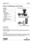
Instruction Manual
V150 and V300 Valves
D101957X012
November 2011
Fisherr Vee-Ballt V150 and V300
NPS 14 through 20 Rotary Control Valves
Contents
Introduction . . . . . . . . . . . . . . . . . . . . . . . . . . . . . . . . . 1
Scope of Manual . . . . . . . . . . . . . . . . . . . . . . . . . . . . . 1
Description . . . . . . . . . . . . . . . . . . . . . . . . . . . . . . . . . 1
Specifications . . . . . . . . . . . . . . . . . . . . . . . . . . . . . . . 2
Installation . . . . . . . . . . . . . . . . . . . . . . . . . . . . . . . . . . 2
Maintenance . . . . . . . . . . . . . . . . . . . . . . . . . . . . . . . . . 5
Packing Maintenance . . . . . . . . . . . . . . . . . . . . . . . . . 5
Stopping Leakage . . . . . . . . . . . . . . . . . . . . . . . . 6
Packing Replacement . . . . . . . . . . . . . . . . . . . . . 6
Ball Seal Replacement . . . . . . . . . . . . . . . . . . . . . . . . 7
Disassembly . . . . . . . . . . . . . . . . . . . . . . . . . . . . . 9
Assembly . . . . . . . . . . . . . . . . . . . . . . . . . . . . . . 10
Bearing and Ball Maintenance . . . . . . . . . . . . . . . . . 11
Disassembly . . . . . . . . . . . . . . . . . . . . . . . . . . . . 12
Assembly . . . . . . . . . . . . . . . . . . . . . . . . . . . . . . 13
Actuator Mounting . . . . . . . . . . . . . . . . . . . . . . . . . 16
Determining Open Position . . . . . . . . . . . . . . . 17
Parts Ordering . . . . . . . . . . . . . . . . . . . . . . . . . . . . . . . 18
Parts List . . . . . . . . . . . . . . . . . . . . . . . . . . . . . . . . . . . 18
Figure 1. Fisher V150 and V300 Vee-Ball NPS 16
Valve
W6087
Introduction
Scope of Manual
This instruction manual provides installation, operation, maintenance, and parts ordering information for NPS 14, 16,
and 20 V150 and for NPS 14 and 16 V300 rotary control valves. For smaller valves (NPS 1 through 12), refer to the
Vee-Ball V150, V200 and V300 Rotary Control Valves NPS 1 through 12 instruction manual (D101554X012). For
information on ENVIRO-SEALt packing, see the ENVIRO-SEAL Packing System for Rotary Valves instruction manual
(D101643X012). Refer to separate manuals for information concerning the actuator, positioner, and mounted
accessories.
Do not install, operate, or maintain V150 and V300 valves without being fully trained and qualified in valve, actuator,
and accessory installation, operation, and maintenance. To avoid personal injury or property damage, it is important
to carefully read, understand, and follow all the contents of this manual, including all safety cautions and warnings. If
you have any questions about these instructions, contact your Emerson Process Management sales office before
proceeding.
Description
The V150 or V300 Vee-Ball valve with a V-notch ball is used in throttling or on-off service. The V150 valve (figure 1) is a
raised-face flanged construction available in CL150. The V300 valve is a raised-face flanged construction available in
CL300. The splined valve shaft connects to a variety of rotary actuators.
www.Fisher.com
Instruction Manual
V150 and V300 Valves
November 2011
D101957X012
Table 1. Specifications
right-hand mounting. Optional valve construction
with optional ball rotation for left-hand mounting is
available upon request.
Valve Sizes and End Connection Styles
V150: NPS 14, 16, and 20 with CL150 raised-face
flanges as shown in table 3
V300: NPS 14 and 16 with CL300 raised-face flanges
as shown in table 3
Ball Rotation
Standard: Ball rotates Counterclockwise to Close
(CCW) when viewed from actuator side of valve
Maximum Inlet Pressure(1)
Consistent with applicable ASME B16.34 or
EN 12516-1 ratings
Optional: Ball rotates Clockwise to Close (CW)
Maximum ball rotation is 90 degrees
Standard Flow Direction
Valve/Actuator Action
Forward (into the convex sealing face of the ball)
With diaphragm or piston rotary actuator,
field-reversible between push-down-to-close
(extending actuator rod closes valve) and
push-down-to-open (extending actuator rod opens
valve)
Actuator Mounting
J Right-hand, or J left-hand as viewed from the
upstream end of the valve. Standard valve
construction with standard ball rotation is with
1. The pressure/temperature limits in this manual and any applicable standard or code limitation for valve should not be exceeded.
Table 2. Valve Sizes, Drive Shaft Diameters, and Valve Assembly Weights
VALVE SIZE
DRIVE SHAFT DIAMETER
VALVE ASSEMBLY WEIGHT
mm
NPS
mm
Inch
350
14
44.5
1-3/4
54.0
2-1/8
54.0 x 50.8
2-1/8 x 2
63.5
2-1/2
400
16
500(1)
20(1)
kg
lb
V150
V300
V150
V300
206
374
545
825
333
510
735
1125
524
---
1155
---
1. NPS 20 available only for V150, not for V300 valves.
Table 3. Valve Sizes, End Connection Styles, and Ratings(1)(2)
VALVE BODY
MATERIAL
FLANGE COMPATIBILITY
RATING
FACE-TO-FACE DIMENSION
CL150 (V150) raised-face
ASME B16.34 CL150
NPS 14 and 16 Valves: ASME B16.10 Short
NPS 20 Valves: 508 mm (20 inches)
CL300 (V300) raised-face
ASME B16.34 CL300
NPS 14 Valves: 381 mm (15 inches)
NPS 16 Valves: 406 mm (16 inches)
CL150 (V150) raised-face
ASME B16.34 CL150
NPS 14 and 16 Valves: ASME B16.10 Short
NPS 20 Valves: 508 mm (20 inches)
CL300 (V300) raised-face
ASME B16.34 CL300
NPS 14 Valves: 381 mm (15 inches)
NPS 16 Valves: 406 mm (16 inches)
WCC steel (standard)
CG8M (317 SST)
1. Do not exceed the material temperature capabilities or the pressure drop limitations shown in bulletin 51.3:Vee-Ball.
2. The pressure/temperature limits in this manual and any application code limitations, should not be exceeded.
Specifications
Specifications for these valves are shown in table 1 and bulletin 51.3:Vee-Ball.
Installation
Key numbers are shown in figure 10, unless otherwise indicated.
2
Instruction Manual
D101957X012
V150 and V300 Valves
November 2011
WARNING
Always wear protective gloves, clothing, and eyewear when performing any maintenance operations to avoid personal
injury.
Personal injury or equipment damage caused by sudden release of pressure may result if the valve assembly is installed
where service conditions could exceed either the valve body rating or the mating pipe flange joint rating. To avoid such
injury or damage, provide a relief valve for overpressure protection as required by government or accepted industry codes
and good engineering practices.
Check with your process or safety engineer for any additional measures that must be taken to protect against process
media.
CAUTION
When ordered, the valve configuration and construction materials were selected to meet particular pressure, temperature,
pressure drop and controlled fluid conditions. Responsibility for the safety of process media and compatibility of valve
materials with process media rests solely with the purchaser and end-user. Since some valve body/trim material
combinations are limited in their pressure drop and temperature ranges, do not apply any other conditions to the valve
without first contacting your Emerson Process Management sales office.
Install the valve with the drive shaft in the horizontal position as shown in figure 1.
WARNING
Do not allow the valve to be installed in the pipeline with the drive shaft in the vertical position because of excessive wear to
component valve parts.
1. If the valve is to be stored before installation, protect the flange mating surfaces and keep the valve cavity dry and
free of foreign material.
2. Install a three-valve bypass around the control valve assembly if continuous operation will be necessary during
inspection and maintenance of the valve.
3. Mounting the Actuator:
a. The valve is normally shipped as part of a control valve assembly, with the actuator mounted on the valve. The
factory makes actuator/valve adjustments before the valve is shipped.
b. If the valve and actuator have been purchased separately or if the actuator has been removed, mount the
actuator according to the Actuator Mounting section of this manual.
4. Be certain the valve and adjacent pipelines are free of any foreign material that could damage the valve seating
surfaces.
5. Be sure the mating line flanges are aligned. Provide standard flat sheet flange gaskets (or spiral wound gaskets with
compression-controlling centering rings) that are compatible with the process fluid.
Refer to figure 2 for required clearance for valve installation and stud length. Lubricate the studs with anti-seize
lubricant.
6. Install the valve using studs and nuts to connect the valve flanges to the pipeline flanges. The seal protector ring
(key 3) end of the valve requires longer line flange studs than standard (see figure 2).
3
Instruction Manual
V150 and V300 Valves
November 2011
D101957X012
Table 4. Required Clearances for Installation of Fisher V150 and V300 Valves
DIMENSION
M(2) (Min.)
A
VALVE
SIZE,
NPS
CL150
ASME B16.10
(Short)(1)
CL300
14
16
20(3)
381
406
508
381
406
---
175
178
235(3)
14
16
20(3)
15.00
16.00
20.00
15.00
16.00
---
6.88
7.00
9.25(3)
B
N
CL150
ASME B16.10
(Short)(1)
CL300
CL150
CL300
152
152
178
197
210
---
133
133
159
178
190
---
6.00
6.00
7.00
7.75
8.25
---
5.25
5.25
6.25
7.00
7.50
---
mm
Inch
1. ASME B16.10 (Short) applies to NPS 14 and 16 valves only.
2. Inlet flange stud bolt length is longer than the standard length as specified in ASME B16.5.
3. NPS 20, CL150 valves do not comply with ASME B16.10 (Short). NPS 20 valves are not available in CL300.
Figure 2. Required Clearances for Installation of Fisher V150 and V300 Valves
B
13B6967-B
A6064-1
N
A
M
Do not attempt to use standard-length line flange studs for the seal protector end of the valve. Refer to figure 2 for
length of flange studs required.
Install all remaining studs. Tighten the nuts in a criss-cross sequence to ensure the flange gaskets are properly loaded.
WARNING
The valve drive shaft is not necessarily grounded to the pipeline when installed. Personal injury or property damage could
result if the process fluid or the atmosphere around the valve is flammable, from an explosion caused by a discharge of
static electricity from the valve components. If the valve is installed in a hazardous area, electrically bond the drive shaft to
the valve.
Standard PTFE packing is composed of a partially conductive carbon-filled PTFE female adaptor with PTFE V-ring packing.
Standard graphite packing is composed of all conductive graphite ribbon packing rings. Alternate shaft-to-valve body
bonding is available for hazardous service areas where the standard packing is not sufficient to bond the shaft to the valve
(see the following step and figure 4).
7. For hazardous applications, attach the optional bonding strap assembly (key 131, figure 4) to the valve drive shaft
(key 6) with the clamp (key 130, figure 4) and connect the other end of the bonding strap assembly to the valve
body with the cap screw (key 23).
8. Connect pressure lines to the actuator as indicated in the actuator instruction manual. When an auxiliary manual
actuator is used with a power actuator, install a bypass valve on the power actuator (if one is not supplied) for use
during manual operation.
4
Instruction Manual
D101957X012
V150 and V300 Valves
November 2011
WARNING
Personal injury could result from packing leakage. Valve packing was tightened before shipment; however, the packing
might need some readjustment to meet specific service conditions. Check with your process or safety engineer for any
additional measures that must be taken to protect against process media.
If the valve has ENVIRO-SEAL live-loaded packing installed, this initial re-adjustment will probably not be required.
Refer to the ENVIRO-SEAL Packing System for Rotary Valves instruction manual (D101643X012) for packing
instructions.
Maintenance
Valve parts are subject to normal wear and must be inspected and/or replaced as necessary. The frequency of
inspection and replacement depends upon the severity of service conditions.
WARNING
The Vee-ball closes with a cutting motion. To avoid personal injury, keep hands, tools, and other objects away from the ball
while stroking the valve.
Avoid personal injury from sudden release of process pressure. Before performing any maintenance operations:
D Do not remove the actuator from the valve while the valve is still pressurized.
D Disconnect any operating lines providing air pressure, electric power, or a control signal to the actuator. Make sure the
actuator cannot suddenly open or close the valve.
D Use bypass valves or completely shut off the process to isolate the valve from process pressure. Relieve process pressure
on both sides of the valve. Drain the process media from both sides of the valve.
D Vent the power actuator loading pressure.
D Use lock-out procedures to be sure that the above measures stay in effect while you work on the equipment.
D Always wear protective gloves, clothing, and eyewear when performing any maintenance operations to avoid personal
injury.
D The valve packing area may contain process fluids that are pressurized, even when the valve has been removed from the
pipeline. Process fluids may spray out under pressure when removing the packing hardware or packing rings.
D Check with your process or safety engineer for any additional measures that must be taken to protect against process
media.
Packing Maintenance
Key numbers are shown in figure 10, unless otherwise indicated. A detailed view of the packing is also shown in figure
3.
If the valve is equipped with the ENVIRO-SEAL Packing System, refer to the ENVIRO-SEAL Packing System for Rotary
Valves instruction manual (D101643X012).
Note
For the ENVIRO-SEAL Packing System, refer to the Parts List section for individual parts (see figure 3). Refer to the ENVIRO-SEAL
Packing System for Rotary Valves instruction manual (D101643X012) for maintenance instructions.
5
V150 and V300 Valves
November 2011
Instruction Manual
D101957X012
Stopping Leakage
For PTFE V-ring packing, leakage around the packing follower and packing flange (keys 17 and 40) can be stopped by
tightening the packing follower nuts (key 20).
If the packing is relatively new and tight on the drive shaft (key 6), and if tightening the packing follower nuts does not
stop leakage, it is possible that the drive shaft is worn or nicked so that a seal cannot be made. If the leakage comes
from the outside diameter of the packing, it is possible that the leakage is caused by nicks, scratches, or corrosion on
the packing box wall.
If the leakage cannot be stopped by the above steps, the packing must be removed and replaced. Inspect the drive
shaft and packing box before installing new packing parts.
Packing Replacement
When replacing the packing, the actuator should not be removed from the valve while the valve is still in the pipeline
or between flanges. Valve/actuator adjustments must be made with the valve out of the pipeline.
Disassembly
1. Isolate the control valve from the line pressure, release pressure from both sides of the valve, and drain the process
media from both sides of the valve. If using a power actuator, shut off all pressure lines to the power actuator,
release pressure from the actuator, and disconnect the pressure lines from the actuator. Use lock-out procedures to
be sure that the above measures stay in effect while you work on the equipment.
2. Remove line bolting, remove the control valve from the pipeline, and place the actuator/valve assembly on a
protected flat surface with the seal protector ring facing up.
3. Remove the actuator cover. Note the orientation of the actuator with respect to the valve body and the lever
orientation with respect to the valve drive shaft (see figure 8).
WARNING
When the actuator is removed from the valve, the ball/shaft assembly may suddenly rotate, resulting in personal injury. To
avoid injury, carefully rotate the ball to the stable position after the actuator is removed.
CAUTION
When removing the actuator from the valve, do not use a hammer or similar tool to drive the lever or actuator off the valve
shaft. Driving the lever or actuator off the valve shaft could damage the ball, seal, and valve.
If necessary, use a wheel puller to remove the lever or actuator from the valve shaft. It is okay to tap the wheel puller screw
lightly to loosen the lever or actuator, but hitting the screw with excessive force could damage the ball, seal, and valve.
Note
Some actuator designs have a bolt inserted in the lever to spread the clamp on the valve spline shaft. Tightening the bolt expands
the splined lever connection allowing the valve shaft to be removed.
4. When removing the lever (do not loosen the actuator turnbuckle adjustment), remove the actuator mounting
screws and nuts (keys 23 and 24), and remove the actuator. (If necessary, refer to the actuator instruction manual
for assistance.)
6
Instruction Manual
D101957X012
V150 and V300 Valves
November 2011
5. If necessary, remove the bonding strap assembly before attempting to remove the packing (see figure 4).
6. Remove the packing flange and nuts and packing follower (keys 20, 40, and 17).
If the valve is equipped with the ENVIRO-SEAL packing system, refer to the ENVIRO-SEAL Packing System for Rotary
Valves instruction manual (D101643X012) for disassembly.
7. Remove the packing parts (key 16 packing set includes additional key numbers) by making a formed wire hook with
a sharp end. Pierce the rings with the sharp end of the hook in order to remove them. Do not scratch the drive shaft
or packing box wall; scratching these surfaces could cause leakage. Clean all accessible metal parts and surfaces to
remove particles that would prevent the packing from sealing. (Note: Metal packing parts are not provided in the
packing set).
Assembly
If the valve is equipped with the ENVIRO-SEAL packing system, refer to the ENVIRO-SEAL Packing System Rotary Valves
instruction manual (D101643X012) for assembly.
1. Install the new packing parts using the parts sequence shown in figure 3.
2. Insert the packing follower and packing flange (keys 17 and 40) and secure them with the packing follower nuts
(key 20). Tighten the nuts far enough to stop leakage during operating conditions.
Note
If the valve is equipped with a bonding strap assembly (figure 4), re-install the assembly.
3. Reconnect the actuator and lever in accordance with the orientations that were noted in step 3 of the disassembly
procedures. If necessary, use figure 8 to identify the correct index marks.
4. If necessary, refer to the appropriate actuator instruction manual to complete actuator assembly and adjustment.
5. When the control valve is in operation, check the packing follower for leakage and retighten the packing follower
nuts (key 20) as necessary.
Ball Seal Replacement
Perform this procedure if the control valve is not shutting off properly, or if seal inspection is necessary. Remove the
actuator/valve assembly from the pipeline.
The actuator may remain mounted on the valve during the ball seal inspection and replacement procedures. Ball seal
assembly details (with key numbers) are also shown in figure 5. Upon inspection, if it is found that the ball, drive shaft,
or bearings need to be replaced, use this procedure to remove the ball seal. Then, proceed to the Bearing and Ball
Maintenance procedures to replace the ball, bearings, or shafts. Then return to this procedure and begin with the
assembly steps in the Ball Seal Replacement section.
During disassembly and re-assembly procedures, handle the seal protector ring, seal, and other parts (keys 3, 11, 13,
and 37) carefully to prevent damage. A new gasket (key 15) is required whenever the seal protector ring (key 3) is
removed.
CAUTION
Due to the Vee-ball shape, take care to never rotate either the front skirted edge of the ball or the circular back edge of the
ball through the ball seal at any time. The seal could be damaged.
7
Instruction Manual
V150 and V300 Valves
November 2011
D101957X012
Figure 3. Packing Arrangements
PACKING FLANGE (KEY 40)
PACKING FOLLOWER (KEY 17)
PACKING SET
(KEY 15)
PACKING RING
(KEY 35)
PACKING BOX RING (KEY 39)
PTFE V-RING PACKING
GRAPHITE RIBBON PACKING
STANDARD PACKING ASSEMBLY
NOTES:
INCLUDES ZINC WASHERS (KEY 36) FOR GRAPHITE RIBBON PACKING ONLY.
A6063
PACKING FLANGE (KEY 102)
PACKING FLANGE NUT (KEY 101)
LUBRICANT (KEY 113)
SPRING PACK ASSEMBLY (KEY 103)
PACKING FLANGE STUD (KEY 100)
ANTI-EXTRUSION RING (KEY 106)
PACKING BOX RING (KEY 107)
PACKING SET (KEY 105)
ENVIRO-SEAL PTFE PACKING SYSTEM
PACKING FLANGE (KEY 102)
PACKING FLANGE NUT (KEY 101)
LUBRICANT (KEY 113)
SPRING PACK ASSEMBLY (KEY 103)
PACKING FLANGE STUD (KEY 100)
PACKING BOX RING (KEY 107)
PACKING SET (KEY 105)
42B8445-B
B2412
ENVIRO-SEAL GRAPHITE PACKING SYSTEM
8
Instruction Manual
V150 and V300 Valves
D101957X012
November 2011
Figure 4. Optional Shaft-to-Body Bonding Strap Assembly
VALVE BODY
37A6528-A
A3143-2/IL
VIEW A-A
ACTUATOR
A
A
The flow ring construction does not use a seal (key 11), radial seal (key 37), or wave spring (key 13). Use this procedure
to remove the seal protector ring for flow ring constructions, but disregard any instructions calling for the seal and
other seal parts.
Disassembly
WARNING
If the actuator is removed from the valve, the ball/shaft assembly may suddenly rotate, resulting in personal injury. To avoid
injury, carefully rotate the ball to the stable position after the actuator is removed. If necessary, lock the ball in a specific
position when directed by the following steps.
Key numbers are shown in figure 10, unless otherwise indicated.
1. Isolate the control valve from the line pressure, release pressure from both sides of the valve, and drain the process
media from both sides of the valve. If using a power actuator, also shut off all pressure lines to the power actuator
and release all pressure from the actuator.
2. Remove line bolting, remove the control valve/actuator assembly from the pipeline, and place the valve on a
protected flat surface with the seal protector ring facing up. Carefully rotate the ball to the open position.
Note
Lifting bolt holes are provided in the seal retainer or flow ring to assist in its removal from the valve body.
3. Remove the retainer screws (key 21). Carefully remove the seal protector ring and gasket (keys 3 and 15). (For flow
ring constructions, go to step 4.)
a. For valves with composition seal, remove the seal (key 11) from the valve body (key 1).
b. For valves with HD metal seal, once the protector ring has been removed from the valve, push the metal seal (key
11) out of the seal protector ring (key 3). Remove the radial seal (key 37). Inspect, clean, or obtain replacement
parts as necessary.
9
Instruction Manual
V150 and V300 Valves
November 2011
D101957X012
It might be necessary to remove the HD metal seal by carefully tapping it with a soft punch and hammer. Take care not
to damage the seal protector ring surfaces.
4. Inspect, clean, or obtain replacement parts as necessary. Inspect the gasket and sealing surfaces on the valve body
(key 1), ball (key 2), ball seal (key 11), and seal protector ring (key 3) for damage.
5. If a replacement ball, drive and follower shafts, or bearings (keys 2, 6, 9, and 10) are needed, proceed to the Bearing
and Ball Maintenance procedure for disassembly and assembly procedures. If only the seal is to be replaced,
proceed to the assembly procedure below.
Assembly
Refer to figure 5 for part and key number locations during seal installation.
1. Thoroughly clean all parts that are to be re-used or obtain replacement parts. Be sure that all sealing surfaces are in
good condition without scratches or wear. If the valve has been installed between line flanges and the flange studs
and nuts have been tightened, always replace the gasket (key 15).
If you have not already done so, lift the valve and place it with the outlet flange face flat on the protected working
surface. Use the lever from the actuator, or provide some other safe method to rotate the ball into the closed position.
The inlet flange face should be up, and the ball approximately centered within the opening.
2. Make sure the ball cannot rotate during seal assembly procedures (read the Warning on page 9).
3. For valves with composition ball seals:
D Install the composition seal (key 11) into the valve body.
D Install the gasket (key 15) on the valve body.
Figure 5. Ball Seal Assembly Detail
RETAINER
SCREW
(KEY 21)
VALVE BODY
(KEY 1)
SEAL PROTECTOR
RING (KEY 3)
GASKET
(KEY 15)
RETAINER
SCREW
(KEY 21)
VALVE BODY
(KEY 1)
RADIAL SEAL
(KEY 37)
SEAL PROTECTOR
RING (KEY 3)
WAVE SPRING
(KEY 13)
V-NOTCH
BALL
(KEY 2)
GASKET
(KEY 15)
COMPOSITION
BALL SEAL
(KEY 11)
43B7128-A
A6066-1
V-NOTCH
BALL
(KEY 2)
HD METAL
BALL SEAL
(KEY 11)
TCM OR TCM III SEAL
HD METAL BALL SEAL
D Install the seal protector ring (key 3) into the valve body. (Go to step 6 below.)
4. For valves with HD metal seals:
D Lubricate with Mag Lub or an equivalent lubricant, and install the radial seal (key 37) into the appropriate groove in
the seal protector ring making sure the open side of the radial seal faces away from the ball.
D Install the wave spring (key 13) on the seal protector ring (key 3).
10
Instruction Manual
D101957X012
V150 and V300 Valves
November 2011
Figure 6. Flow Ring Construction
SEAL
PROTECTOR
RING
E0849
D Install the HD metal seal (key 11) into the seal protector ring (key 3), past the radial seal. While pushing it past the
radial seal, make sure the HD metal seal is level.
D To assist with break-in of the HD metal seals, it is recommended that the ball and seal be lubricated. Apply dry film
lubricant to the seat of the HD metal seal (key 11) and to the face of the ball.
Note
During break-in, if the Vee-Ball rotation is not smooth, it may be necessary to tighten the packing slightly to dampen any tendency
for stick-slip motion of the ball and seal assembly.
5. Install the HD metal ball seal/seal protector ring assembly into the valve body (key 1). Go to step 6 below.
6. Install the retaining screws (key 21) that secure the seal protector ring (key 3) to the valve body (key 1). Tighten the
screws (key 21).
7. If necessary, refer to the Packing Maintenance procedures to install the packing. Install the actuator using the
Actuator Mounting procedures or to the appropriate actuator instruction manual.
Bearing and Ball Maintenance
Procedures for disassembly and assembly of the bearings and ball cannot be accomplished until the ball seal and valve
packing are loosened.
D Refer to the Packing Maintenance procedures to remove the actuator.
D Refer to the Ball Seal Replacement procedures to remove the seal from the valve.
D Install an ``eye'' bolt into the threaded hole within the ball cavity (see figure 10). (Note: The eye bolt provides a
method for lifting and controlling the rotation of the ball during the following procedures. (Read the following
Warning.)
D When ball seal disassembly steps are complete, return to this section.
If you have not already done so, place the valve on a flat protected working surface with the seal side down, prior to
removing and installing the ball and bearings. Key numbers in this procedure are shown in figure 10, unless otherwise
indicated.
11
V150 and V300 Valves
Instruction Manual
November 2011
D101957X012
Disassembly
WARNING
When the actuator is removed from the valve, the ball may suddenly rotate, resulting in personal injury. To avoid injury,
carefully rotate the ball to a stable position.
Once the drive and follower shafts have been removed from the valve body, the ball may fall out of or into the valve body.
To avoid personal injury or damage to the sealing surfaces of the ball, provide a hoist to support the ball to prevent it from
falling as the shafts are being removed.
1. Carefully lift the valve and set it on the edge of the flanges so the ball is in the open position, and in the down
position. (Note: The weight of the ball should turn it into the open position.) Block the drive end of the valve body to
hold the shaft in a horizontal position.
2. Drive the pins (key 7) out of the drive shaft and out of the follower shaft (keys 6 and 9).
Both pins are tack welded to the ball ears. To remove a pin, insert a pin punch into the open hole, opposite the tack
welded side, and break the tack weld while driving the pin out.
3. Carefully lift the valve and place the valve on the working surface with the seal side down (read the Warning above).
Because of the weight of the ball, it should rotate so the contoured sealing surface of the ball is resting on the surface.
4. Remove the flange nuts (key 47), the bottom flange (key 44), and gasket (key 45) from the valve. Use a hoist to lift
valve body slightly.
Make sure the sealing surface of the ball is not damaged while removing the follower shaft (key 9).
5. Push the follower shaft (key 9) into the center of the ball. For valves with metal bearings, remove the thrust washer
(key 38).
6. Pull the drive shaft (key 6) out of the actuator side of the valve body. For valves with metal bearings, remove the
thrust washer (key 38).
7. Removing the bearings (key 10):
a. For PEEK bearings, remove the bearings by hand. If the bearings are tight in the valve body, pull or drive them out
with a slight pressure.
b. For metal bearings, use a press and ram to remove the drive shaft bearings out of the valve body. Refer to figure
7 for ram dimensions.
D To remove the follower shaft bearing from the bottom flange (key 44), use a blind-hole bearing puller similar to
CG2545AB, which is made by Snap-on Tools. If you do not have such a tool, you can machine the bearing out of the
bottom flange.
Note
For proper shutoff performance, the ball and seal require the bearing (key 10) to be positioned correctly. If you removed the
bearings (key 10), be sure to locate the new bearings as shown in figure 7.
8. Thoroughly clean all surfaces of parts that are to be re-used or obtain replacement parts. Upon reassembly, the pins
needs to be tack welded to the ball ears. Remove excess weld material, if the parts are to be used during
re-assembly.
12
Instruction Manual
V150 and V300 Valves
D101957X012
November 2011
Assembly
1. Inspect all sealing surfaces to ensure they are in good condition and without scratches or wear. Thoroughly clean all
parts and make sure they are free of oil or grease.
2. Installing bearings (key 10):
a. For PEEK bearings, install the drop-in bearings by hand. The bearing flanged end should touch the drive shaft
bearing support surface (see figure 10). Also, install the bearing (key 10) into the bottom flange (key 44). The
bearing flange should touch the surface of the bottom flange.
b. For metal bearings (key 10):
D For the valve body, use a press and ram to install the bearings. Refer to figure 7 for dimensions and tolerances of the
ram and bearings.
D Press the bearing in until it is flush with the valve body (key 1).
The acceptable tolerance for bearing location is: flush with the valve body to 1.5 mm (0.06 inches) inside the bearing
bore. That is, the bearings should not protrude into the flow cavity of the valve.
D Press the bearing into the bottom flange, using the same tolerances shown for bearing installation into the valve
body.
WARNING
The ball might be damaged if it is allowed to fall into the valve body. To avoid personal injury or damage to the sealing
surfaces, support the ball to prevent it from falling into the valve body cavity.
3. Installing the ball, drive and follower shafts (keys 2, 6, and 9):
D If you have not already done so, place the valve body (key 1) on a flat protected working surface with the seal side
flat on the working surface.
D In the the next step, make sure the splined ear of the ball is aligned with the packing box side of the valve body.
CAUTION
The ball might be damaged if it is allowed to hit the flange edge or interior of the valve cavity while it is being lowered into
the valve body.
D Using the ”eye” bolt in the center of the ball cavity, lift the ball above the valve. Carefully, start lowering the ball,
splined ear first, down into the valve body through the outlet flange. When the ball ear enters the valve body, it
needs to be misaligned with the drive shaft bearing support.
As the ball clears the outlet opening, turn and rotate the ball as necessary to align the splined ball ear with the drive
shaft bearing support (see figure 10).
Allow the ball to come to rest on the contoured sealing surface of the ball on the protected surface.
4. Carefully lift the valve body until the drive shaft (key 6) can be inserted through valve shaft bore and bearing (key
10), and into the drive shaft/splined ear of the the ball.
13
Instruction Manual
V150 and V300 Valves
November 2011
D101957X012
Note
1. See note 1, figure 10.
2. For valves with metal bearings, hold the thrust washer (key 38, figure 10) in place before inserting the drive shaft.
Make sure that the ``O'' mark on the shaft aligns with the ``O'' mark on the ball ear, within the ball cavity. Insert the
drive shaft (key 6) into the ball. If the ``O'' marks are aligned correctly, the drive shaft pin (key 7) should slide through
the ball ear and drive shaft.
D With the valve body still lifted, align the ball follower shaft bore with the opening in the valve body for the lower
flange (key 44). [Note: For valves with metal bearings, hold the thrust washer (key 38, figure 10) in place before
inserting the follower shaft.] While aligning the pin holes, insert the follower shaft into the ball.
D Place the gasket (key 45) in position on the bottom flange (key 44). Insert the bottom flange into the valve body,
onto the follower shaft, and thread the bottom flange nuts (key 47) onto the studs (key 46). Hand tighten the nuts.
Figure 7. Ram Construction and Bearing Installation
VALVE BODY
BEARING
1.5 TO 0.00
(0.06 TO 0.00)
BOTTOM
FLANGE
6.35
(0.25)
D
BEARING
d
L
RAM DIMENSIONS
RAM CONSTRUCTION DETAIL
43B7128-A
A6062-1
METAL BEARING INSTALLATION
mm
(INCHES)
Table 5. Bearing Ram Dimensions
RAM LENGTH
mm
14
16
20
14
RAM DIAMETER
L
VALVE SIZE, NPS
172
178
216
D
Inch
6.75
7.00
8.50
d
mm
Inch
mm
Inch
51.30
2.02
44.45
1.75
51.05
2.01
44.20
1.74
60.96
2.40
53.91
2.125
60.71
2.39
53.72
2.115
70.35
70.10
2.77
2.76
63.50
63.25
2.50
2.49
Instruction Manual
D101957X012
V150 and V300 Valves
November 2011
Figure 8. Index Mark for Actuator Lever Orientation
NOTE:
1. ARROW ON LEVER INDICATES DIRECTION OF ACTUATOR THRUST TO CLOSE VALVE.
5. Installing the pins (key 7):
CAUTION
The ball might be damaged if it is allowed to hit the flange edge or interior of the valve cavity while it is being lowered into
the valve body.
D Lift the valve and place it on the edge of both flanges. Make sure the ball is in its open position, and in the lower half
of the valve cavity. Block the packing box side of the valve so the drive shaft is horizontal.
D Insert the pin (key 7) into the ball ear and follower shaft until it is flat with the ball ear surface. (Note: the pin does
not extend the full width of the ball ear.
D Refer to the Packing Replacement procedures and install the packing parts as described in that section. Slightly
tighten the packing nuts (key 20).
15
V150 and V300 Valves
Instruction Manual
November 2011
D101957X012
D Using a pry bar, insert the bar between the ball ear and the follower shaft side of the valve body. Move the ball
tightly towards the packing box side of the valve body, and against the bearing flange or thrust washer. The ball
should be centered within the seal cavity.
D Again, insert the bar between the ball ear and the follower shaft side of the valve body. While holding the ball in
place, tighten the packing box nuts (key 20).
If the ball is not held in place while tightening the packing box nuts, the ball will move to an off-center position.
6. Welding the pins (key 7):
Note
When welding the pins to the ball ears, use a compatible filler rod material. For CG8M (317 stainless steel) balls use 317L (most
preferred), 316L, or 309L (least preferred) filler rod.
Tack weld both pins (key 7) to the ball ears with a 10 mm (3/8-inch) diameter weld. (Note: Good weld penetration is
required on both the pin and ball ear.)
7. Tighten the bottom flange nuts using the following torque values: For NPS 14 valves, 102 NSm (75 lbfSft); for NPS
16 valves, 141 NSm (104 lbfSft); and for NPS 20 valves, 176 NSm (130 lbfSft).
8. Lift the valve and place it with the outlet flange face flat on the protected working surface. Use the lever from the
actuator, or provide some other safe method to rotate the ball into the closed position. The inlet flange face should
be up to allow the installation of the ball seal. The ball should be centered within the valve opening.
9. Refer to the Ball Seal Replacement procedures to install the ball seal and seal protector ring.
Actuator Mounting
Standard flow direction is with the seal protector ring (key 3) facing upstream. Install the valve with the drive shaft
horizontal and the ball closing in the downward direction (see figure 8).
WARNING
The Vee-ball (key 2, figure 10) closes with a cutting motion. To avoid personal injury, keep hands, tools, and other objects
away from the ball while stroking the valve.
Actuator travel must be adjusted before installing the valve in the pipeline because it is not possible to accurately
determine the closed position once the valve is in the line.
The actuator can be right or left-hand mounted in any of four positions as shown in figure 8.
Note
Right-hand mounting–Actuator is on the right side of the valve when viewed from the valve inlet.
Left-hand mounting–Actuator is on the left side of the valve when viewed from the valve inlet.
16
Instruction Manual
V150 and V300 Valves
D101957X012
November 2011
Figure 9. Determining the Ball Position
VALVE BODY
SEAL RETAINER
OR FLANGE FACE
ROTATION
90_
FLOW
OPEN VALVE POSITION
A6065
CLOSED VALVE POSITION
However, when changing the valve from right to left-hand mounting, or vice versa, a different valve drive shaft and ball
are required. If a new shaft and ball are required, refer to the Bearing and Ball Maintenance section and the Parts List in
this manual.
Note
If necessary, it is possible to mount the valve in the left-hand position with the ball rotating to the top of the valve. This will require
a non-standard ball. The ball rotates clockwise to close. Refer to figure 8, or contact your Emerson Process Management sales
office for assistance.
Determining Open Position
The valve must be removed from the pipeline to check the position of the ball.
1. Rotate the ball to the open position. The open position of the ball is shown in figure 9.
2. Adjust the actuator linkage until the open position is obtained using the appropriate actuator instruction manual
procedures.
3. Stroke the valve to the closed position.
Make sure the actuator does not stroke the ball more than 90 degrees when rotating to the closed position (see figure
9).
17
Instruction Manual
V150 and V300 Valves
November 2011
D101957X012
WARNING
Use only genuine Fisher replacement parts. Components that are not supplied by Emerson Process Management should
not, under any circumstances, be used in any Fisher valve, because they may void your warranty, might adversely affect the
performance of the valve, and could cause personal injury and property damage.
Parts Ordering
A serial number is assigned to each valve and stamped on the nameplate. Always refer to the valve serial number when
corresponding with your Emerson Process Management sales office regarding spare parts or technical information.
When ordering replacement parts, also specify the complete 11-character part number from the Parts List.
Parts List
Key
Note
Part numbers are shown for recommended spares only. For part
numbers not shown, contact your Emerson Process Management sales
office.
Key
1
2
3
6
7*
9
10*
11*
13*
15*
18
Description
Part Number
Valve Body Assembly
If a part number is required, contact
your Emerson Process Management sales office.
Ball
Seal Protector Ring
Drive Shaft
Pin, S20910 (2 req'd)
NPS 14
13B6896X012
NPS 16
13B0697X012
NPS 20
13B6060X012
Follower Shaft
Bearing (2 req'd)
See following table
Ball Seal
See following table
Wave Spring, N07750 (Inconel)
Use w/HD Metal Seal
NPS 14
23B7013X012
NPS 16
23B0695X012
NPS 20
23B6064X012
Gasket, laminated graphite
Standard Construction
NPS 14
13B6894X022
NPS 16
13B0692X022
NPS 20
13B6058X022
Description
16*
17
19
20
21
23
24
25
26
27
28
30
31
35*
36*
37*
Part Number
Use w/ oxygen service
NPS 14
13B6894X032
NPS 16
13B0692X032
NPS 20
13B6058X032
Packing Set, Set includes PTFE V-ring packing with one carbonfilled conductive ring, male adapter, and female adapter
NPS 14
12A9057X022
NPS 16
1R5162X0012
NPS 20
1R6699X0012
Packing Follower
Packing Follower Stud (2 req'd)
Packing Follower Nut (2 req'd)
Retainer Screw, (used w/B8M)
Actuator Mounting Screw (4 req'd)
Actuator Mounting Nut, stainless steel (4 req'd)
Pipe Plug
Identification Nameplate
Drive Screw
Flow Arrow (2 req'd)
Body Size/Serial Number Nameplate,
Nameplate Wire (not shown)
Packing Ring, graphite ribbon (4 req'd)
NPS 14
12A9140X032
NPS 16
1V949601652
NPS 20
12A9142X012
Packing Washer, zinc (Use w/graphite ribbon
packing, 3 req'd)
NPS 14
14A9772X012
NPS 16
12B5927X012
NPS 20
14A9774X012
Radial Seal, PTFE/CG/N10276 (alloy 276C)
Use w/HD Metal Ball Seal
NPS 14
13B7012X012
NPS 16
13B0696X012
NPS 20
13B6065X012
*Recommended spare parts
Instruction Manual
V150 and V300 Valves
D101957X012
November 2011
Figure 10. Fisher V150 and V300 Valve Assembly
BALL EAR
ZERO MARK
DRIVE SHAFT
TACK WELD
PIN HERE
43B6886-A
VIEW A
SEE VIEW A
DRIVE SHAFT
BEARING SUPPORT
COMPOSITION SEAL
METAL BEARING
NOTES:
THE V-NOTCH BALL EXTENDS TO THIS POINT WHEN ROTATED 180 DEGREES AWAY FROM THE CLOSED POSITION. SEE BEARING AND V-NOTCH BALL
ASSEMBLY PROCEDURES.
2. KEYS 24, 30, 31, 35, AND 36 ARE NOT SHOWN.
43B7128-A
19
Instruction Manual
V150 and V300 Valves
November 2011
Key
38
39
40
44
45*
46
47
D101957X012
Description
Part Number
Thrust Washer (4 req'd)
Packing Box Ring
Packing Flange
Bottom Flange
Gasket, S31603 (316L SST)
V150
NPS 14
NPS 16
NPS 20
V300
NPS 14
NPS 16
Bottom Flange Stud (6 req'd)
Hex Nut (6 req'd)
Key
Part Number
103
Spring Pack Assembly
105* Packing Set
PTFE
NPS 14
NPS 16
NPS 20
Graphite
NPS 14
NPS 16
NPS 20
106* Anti-Extrusion Ring (2 req'd)
NPS 14
NPS 16
NPS 20
107* Packing Box Ring
NPS 14
NPS 16
NPS 20
111
Tag
112
Tie Cable
113
Lubricant
13B6895X012
13B0690X012
13B6059X012
14B5575X012
14B5354X012
ENVIRO-SEAL Packing System (figure 3)
100
101
102
Description
Packing Flange Stud
Packing Flange Nut
Packing Flange
14B3049X012
14B3203X012
14B3060X012
13B8816X152
13B8816X182
13B8816X162
14B3045X012
14B3199X012
14B3056X012
12A9058X012
12B3373X012
12A9084X012
23B6562X012
18A9401X012
Key 10* Bearing (2 req'd)
BEARING MATERIAL
VALVE
SIZE,
NPS
PEEK(1)/PTFE
S44004
Alloy 6B
Silver Plated
Alloy 6B
14
14B3651X012
14A6551X012
14A6552X012
14A6540X012
16
14B3653X012
13B7124X012
13B7124X022
13B7125X012
20
14B3655X012
14A6555X012
14A6556X012
14A6542X012
1. PEEK stands for poly-ether-ether-ketone.
Key 11* Ball Seal
COMPOSITION
FORWARD FLOW ONLY
TCM Plus
TCM Ultra
VALVE SIZE,
NPS
HEAVY DUTY METAL SEAL
CF10SMnN
CD7MCuN
Alloy 6B
14
13B6897X032
13B6897X042
33B7010X012
33B7010X022
33B7010X032
16
1V6298X0022
1V6298X0032
33B0693X012
33B0693X022
33B0693X032
20
13B6061X032
13B6061X042
33B6062X012
33B6062X022
33B6062X032
*Recommended spare parts
Neither Emerson, Emerson Process Management, nor any of their affiliated entities assumes responsibility for the selection, use or maintenance
of any product. Responsibility for proper selection, use, and maintenance of any product remains solely with the purchaser and end user.
Fisher, Vee-Ball, and ENVIRO-SEAL are marks owned by one of the companies in the Emerson Process Management business division of Emerson Electric Co.
Emerson Process Management, Emerson, and the Emerson logo are trademarks and service marks of Emerson Electric Co. All other marks are the property
of their respective owners.
The contents of this publication are presented for informational purposes only, and while every effort has been made to ensure their accuracy, they are not
to be construed as warranties or guarantees, express or implied, regarding the products or services described herein or their use or applicability. All sales are
governed by our terms and conditions, which are available upon request. We reserve the right to modify or improve the designs or specifications of such
products at any time without notice.
Emerson Process Management
Marshalltown, Iowa 50158 USA
Sorocaba, 18087 Brazil
Chatham, Kent ME4 4QZ UK
Dubai, United Arab Emirates
Singapore 128461 Singapore
www.Fisher.com
20
EFisher Controls International LLC 1987, 2011; All Rights Reserved