1
Instruction Manual
Form 5482
February 2005
Cryogenic-Rotary Valve
CAUTION
Never use a wrench or pliers on the
valve shaft. A damaged shaft could cut
the packing and allow leakage.
1. Before loosening any parts, isolate the valve from
the line pressure, release pressure from both sides
of the valve body, and drain the process media from
both sides of the valve.
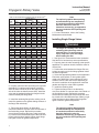
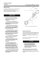
2. Then, remove the hex nuts (key 18) and lift off
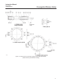
the packing follower (key 11). The packing (key 13)
is now accessible. Refer to figure 6 for details of the
blowout protection.
3. Use a packing extractor to remove the packing.
Insert the corkscrew-like end of the tool into the first
piece of packing and pull firmly to remove the
packing. Repeat this process until all packing has
been removed.
Note
For valves equipped with non-metallic
(PTFE composition) bearings, perform
the following step to inspect and/or
replace the outboard bearing (key 10).
4. Using a formed hook or probe, carefully remove
the packing ring (key 12) and inspect the outboard
bearing (key 10) for excessive intrusion or wear.
Outboard bearings are only found on the 3- through
12-inch sizes. If necessary, remove the bearing
carefully using needle-nose pliers and install a new
bearing and existing packing ring using the packing
follower (key 11) as a driver.
CAUTION
Be careful when cleaning the packing
box. Scratches to the shaft or inside
diameter of packing bore might cause
leakage.
5. Before installing new packing, clean the packing
box.
6. Install new packing (key 13) one ring at a time,
using the packing follower (key 11) as a driver. If
using split-ring packing, stagger the splits in the
rings to avoid creating a leak path.
7. Reinstall all parts. Tighten the packing follower
nuts (key 18) as needed to stop leakage under
operating conditions.
8
Removing the Valve from the Pipeline
1. Disconnect any operating lines providing air
pressure, electric power, or a control signal to the
actuator. Be sure the actuator cannot suddenly open
the valve. Vent the power actuator loading pressure.
2. Use bypass valves or completely shut off the
process to isolate the valve from process pressure.
Relieve process pressure on both sides of the valve.
Drain the process media from either side of the
valve.
CAUTION
Damage to the valve disc, piping or
pipe flanges can occur if the disc is
not closed when the valve is being
removed from the pipeline. If
necessary, stroke the actuator to place
the disc in the closed position while
removing the valve from the pipeline.
3. Loosen the flange bolting that holds the valve.
Make sure the valve cannot slip or twist while
loosening and removing the bolting.
4. Make certain the valve disc is closed and remove
the valve from the pipeline. Support the valve
properly and move the valve to an appropriate work
area.
Removing/Installing the Seal Ring
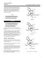
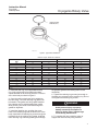
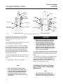
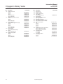
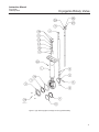
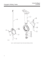
Unless otherwise indicated, key numbers and part
names are listed in figures 7 and 8.
Note
For valves large enough to be safely
placed on a flat surface without
tipping, it is possible to replace the
seal ring (key 7) while the actuator is
mounted to the valve and can be
accomplished by cycling the valve to
90 degrees open.
1. After removing the valve from the pipeline,
remove the manual or power actuator. Manually
rotate the drive shaft (key 4) counterclockwise until
the disc has moved a full 180 degrees away from the
closed position.
2. Lay the valve flat on a work bench in a secure
position with the retaining ring (key 2) and retaining
ring screws (key 19) facing up. Properly secure the
valve on a suitable worktable so it can not slip, twist,
or fall during maintenance. Remove all retaining ring
screws.