1
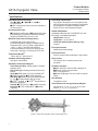
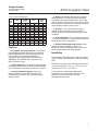
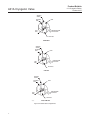
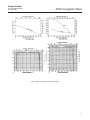
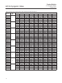
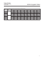
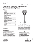
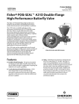
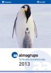
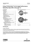
Product Bulletin
21.1:Cryogenic-Rotary
D500230X012
October 2010
A31A Cryogenic Valve
Fisherr POSI-SEALt A31A Cryogenic High
Performance Butterfly Valve
Description
The Fisher A31A Cryogenic High Performance
Butterfly Valve (HPBV) is designed for extreme
temperature cryogenic services and features a valve
body extension which positions the packing system
and the actuator away from the extreme
temperatures. The NPS 3 through 12 valves feature
a unique one-piece investment cast extension
housing (see figures 1 and 2). The NPS 14 through
24 valves employ a two-piece fabricated extension
housing. The valve also features a metal NOVEX
seal as standard providing tight shutoff, low
operating torques and the rugged durability needed
for cryogenic service.
The A31A Cryogenic HPBV has been developed as
a valve/actuator package with a Double D drive shaft
(standard for NPS 3 through 12) to allow easy, direct
mounting to the Fisher 1035 Rack and Pinion
actuator, eliminating the need for external coupling
systems. Also available are keyed shaft (standard
for NPS 14 through 24) and splined drive shafts to
allow easy mounting to other Fisher actuators.
The A31A Cryogenic HPBV is available in either
flangeless (wafer) or single flange styles, and
S31600 (316 SST) is the standard valve body and
disc material. This valve is offered in full rated
CL150 and CL300 pressure classes.
Contents
Features . . . . . . . . . . . . . . . . . . . . . . . . . . . . . . . . . . 3
Specifications . . . . . . . . . . . . . . . . . . . . . . . . . . . . . 2
Installation . . . . . . . . . . . . . . . . . . . . . . . . . . . . . . . . 3
Coefficients . . . . . . . . . . . . . . . . . . . . . . . . . . . . . . 16
Tables
Approximate Weights . . . . . . . . . . . . . . . . . . 3
Material Temperature Ratings . . . . . . . . . . 6
Dimensions . . . . . . . . . . . . . . . . . . . . . . . . . . 7
W7451
Figure 1. Fisher POSI-SEAL A31A Cryogenic Valve with 1035 Actuator
www.Fisher.com
Product Bulletin
21.1:Cryogenic-Rotary
October 2010
A31A Cryogenic Valve
Specifications
Valve Body Sizes and Ratings
NPS J 3, J 4, J 6, J 8, J 10, and J 12
CL150 and 300
J NPS 14 through 24 valves are also available in
CL150 and 300.
Valve Body Classification
Face-to-face dimensions are in compliance with
MSS SP68 and API 609 standards; valve bodies
are designed for installation between ASME
B16.5 CL150 or 300 raised-face flanges
End Connection Style
J Flangeless, wafer-style or J single flange valve
body designed to fit between raised-face mating
flanges per ASME B16.5 CL150 or 300
Shutoff Classification
Maximum Inlet Pressure/Temperature(1)
Consistent with CL150 and CL300
pressure/temperature ratings per ASME B16.34,
except that 38_C (100_F) rating is applicable to
254_C (425_F). NOVEX seal maximum
pressure/temperature rating is the same as the
valve body. See figure 4 for rating of CTFE seal.
Unidirectional Reverse flow. Per ANSI/FCI 70-2 and
IEC 60534-4 at ambient temperature
NOVEX Seal: Class VI
CTFE Seal: 1/10 of Class IV
CTFE Seal with Aluminum back-up ring:
Class VI
Flow Characteristic
Modified equal percentage
Temperature Range(1)
234 to 260_C (425 to 500_F)
Flow Coefficients
See the section titled Coefficients in this bulletin
Available Seal Configurations
See figure 3 and table 2
Noise Levels
See Catalog 12 for sound pressure level
prediction
Standard Construction Materials
Valve Body and Disc: ASTM grades of S31600
stainless steel
Disc Coating:Hardcoating Standard (Chrome or
Nickel)
Shaft: J ASTM grade of S17400 H1150M SST,
J N05500 (Optional), J N07718 (Optional)
Seal Ring: J S31600 (316 SST) NOVEX Std for
CL 150, J S21800 NOVEX Std for CL300,
J CTFE(2) optional, or J CTFE(2) with Aluminum
Back-up ring optional
Packing: J PTFE V-ring, or J graphite (optional)
Bearings: J PTFE Composition, or J bronze
(optional)
Available Actuators
J Rack and Pinion 1035 for NPS 3 through 12,
J Bettis G Series for keyed shaft
NPS 14 through 24 or
J Rotary Diaphragm 1051 and 1052 for splined
shafts
Disc Rotation
Clockwise to close
Valve Dimensions and Approximate Weights
See figures 6, 7, 8, 9, 10, 11, 12, and 13 and
tables 1, 3, 4, 5, 6, 7, 8, 9 and 10.
1. The pressure/temperature limits in this bulletin, and any application code or standard limitation, should not be exceeded.
2. CTFE not recommended for fast cycling, less than 2 seconds.
W7449
Figure 2. Fisher A31A Cryogenic Valve, Single Flange Style
2
Product Bulletin
21.1:Cryogenic-Rotary
October 2010
A31A Cryogenic Valve
Table 1. Approximate Weights
VALVE
SIZE,
NPS
WAFER
CL150
SINGLE
FLANGE
CL150
WAFER
CL300
SINGLE
FLANGE
CL300
kg
lbs
kg
lbs
kg
lbs
kg
lbs
3
12
27
16
36
12
27
16
35
4
21
46
22
48
21
46
24
52
6
24
53
28
61
24
53
28
61
8
34
75
40
89
47
104
52
115
10
57
125
67
148
80
176
100
220
12
74
164
93
206
103
227
135
298
14
87
191
120
265
142
314
249
548
16
133
294
182
401
213
470
325
716
18
170
374
231
510
259
570
434
956
20
210
463
302
665
401
884
582
1282
24
326
719
455
1004
512
1128
863
1903
Features
D Cryogenic Seal Improvement— The NOVEX
pressure-assisted metal seal design provides tight
shutoff (ANSI Class VI, ambient) and permits the
use of smaller, less expensive actuators in
applications requiring full ASME B16.34 shutoff
capabilities. The NOVEX seal is standard on all
A31A Cryogenic valves.
D Safety—Redundant shaft retention provides
added protection. The packing follower and shaft
step interact to hold the shaft securely in the valve
body. The NPS 3 through 12 valves use a one-piece
packing follower, and the NPS 14 through 24 valves
use a two-piece follower (see figure 5).
D Strength— The cast S31600 one-piece
extensions are welded directly onto the NPS 3
through 8 valves for greater strength under service
conditions.
D Easy Installation—The valve body self-centers
on the line flange bolts as a fast, accurate means of
centering the valve in the pipeline.
D Reliable Flange Gasketing Surface—Seal
retainer screws are located so there is no
interference with the sealing function of either flat
sheet or spiral wound line flange gaskets.
Installation
Recommended installation for the A31A Cryogenic
valve is with the shaft upstream of the seal (reverse
flow).
D Direct Actuation—The A31A Cryogenic NPS 3
through 8 Double D shaft allows direct mounting with
the 1035 actuator, eliminating the need for a coupler.
Dimensions for wafer-style and single-flange valves
are shown in figures 6, 7, 8, 9, 10, 11, 12, and 13
and tables 3, 4, 5, 6, 7, 8, 9 and 10.
D Excellent Shutoff Integrity—Concentric
rotation enables the valve disc to remain in the
closed position in spite of line pressure surges or
actuator failure.
For assistance in selecting the appropriate
combination of actuator action and open valve
position, consult your Emerson Process
Management sales office.
3
Product Bulletin
21.1:Cryogenic-Rotary
October 2010
A31A Cryogenic Valve
GRAPHITE
GASKET
RETAINING
RING
BODY
HIGH PRESSURE
AT SHUTOFF
SEAL
RING
VALVE DISC
NOVEX SEAL
GRAPHITE
GASKET
RETAINING
RING
BODY
HIGH PRESSURE
AT SHUTOFF
SEAL
RING
VALVE DISC
CTFE SEAL
GRAPHITE
GASKET
RETAINING
RING
BODY
HIGH PRESSURE
AT SHUTOFF
SEAL
RING
VALVE DISC
16B5083
CTFE / ALUM SEAL
Figure 3. Available Seal Configurations
4
Product Bulletin
21.1:Cryogenic-Rotary
October 2010
A31A Cryogenic Valve
C0759-1
CTFE
CTFE
A4132-1
CL150, CTFE SEAL
A3715-2
CL300, CTFE SEAL
Figure 4. Maximum Pressure/Temperature Ratings
5
Product Bulletin
21.1:Cryogenic-Rotary
October 2010
A31A Cryogenic Valve
Table 2. Material Temperature Ratings
COMPONENT AND MATERIAL OF CONSTRUCTION
TEMPERATURE RANGE
_C
_F
254 to 260
–425 to 500
254 to 260
–425 to 500
254 to 260
–425 to 500
196 to 260
198 to 260
254 to 260
–320 to 500
325 to 500
425 to 500
254 to 163
254 to 260
–425 to 325
–425 to 500
254 to 232
254 to 260
–425 to 450
425 to 500
NOVEX S31600 Seal Ring (CL150) (standard)
NOVEX S21800 Seal Ring (CL300) (standard)
254 to 260
254 to 260
425 to 500
425 to 500
CTFE Cryogenic Seal Ring
254 to 149
425 to 300
Valve Body
CF8M (316 SST) CL150 and 300
Disc
CF8M (316 SST)
Disc Coating
Hard Coating(1)
Shaft
S17400 H1150M (standard)
N05500
N07718
Bearings
PTFE Composition Rexnord (standard)
Bronze
Packing
PTFE Packing (standard)
Graphite
Seal Ring
1. The material for hard coating on the disc is either hard chrome plating or Electroless Nickel Coating (ENC) depending upon availability.
SHAFT
SHAFT
STUD
HEX NUT
PACKING
FLANGE
PACKING
FOLLOWER
HEX NUT
ANTI-BLOWOUT
FLANGE
PACKING RING
STUD
HEX NUT
V-RING PACKING
ANTI-BLOWOUT
SHAFT SHOULDER
OUTBOARD
BEARING
PACKING
FOLLOWER
SHAFT SHOULDER
TYPICAL PTFE
V-RING
PACKING
A7090
16B5082
NPS 3 THROUGH 12
NPS 14 THROUGH 24
Figure 5. Anti-Blowout Protection
6
Product Bulletin
21.1:Cryogenic-Rotary
October 2010
A31A Cryogenic Valve
Table 3. Dimensions, Wafer Style Valves, CL150, NPS 3 through 8
VALVE
SIZE,
NPS
A
D
E
F
F1
G
J
K
3
48
87
83
10
19
79
146
375
4
54
113
83
22
25
95
178
451
6
57
165
83
41
51
127
248
8
64
210
83
65
68
152
---
R(1)
S
T
U
V
FLAT
LENGTH
FLAT
SIZE
71
133
16
152
32
117
25
11
94
171
19
152
32
117
25
14
489
148
219
25
152
32
117
25
17
679
197
273
25
152
32
117
25
17
M(2)
mm
Inches
3
1.88
3.44
3.25
0.38
0.75
3.13
5.75
14.75
2.82
5.25
0.625
6.0
1.25
4.63
1.0
0.436
4
2.13
4.44
3.25
0.88
1.0
3.75
7.0
17.75
3.69
6.75
0.75
6.0
1.25
4.63
1.0
0.561
6
2.25
6.50
3.25
1.63
2.0
5.0
9.75
19.25
5.82
8.63
1
6.0
1.25
4.63
1.0
0.687
8
2.50
8.25
3.25
2.57
2.69
6.0
---
26.75
7.75
10.75
1
6.0
1.25
4.63
1.0
0.687
1. Face-to-face dimensions are in compliance with MSS SP68 and API 609 specifications.
2. Minimum I.D. is the minimum pipe or flange I.D. required for disc swing clearance.
CLOCKWISE TO CLOSE
FLAT
LENGTH
OS
CLOSED POSITION
MATCH MARKS
E
T
102 [4.00]
FLAT SIZE
6 HOLES
O 0.56
THROUGH
A
VENT
(SUPPLIED
PER
REQUEST)
U
V
TYPICAL VALVE MOUNTING
DISC
SHOWN IN
FULL OPEN
POSITION
K
D
PORT
DIAMETER
M MIN I.D. REQUIRED
FOR DISC SWING
CLEARANCE
G
F1
F
OR
OJ
VALVE BODY
FLOW
mm (INCHES)
16B4210
Figure 6. Dimensions, Wafer Style Valves, CL150, NPS 3 through 8 (also see table 3)
7
Product Bulletin
21.1:Cryogenic-Rotary
October 2010
A31A Cryogenic Valve
Table 4. Dimensions, Single Flange Style Valves, CL150, NPS 3 through 8
VALVE
SIZE,
NPS
A
D
E
F
F1
J
K
M(2)
3
48
87
83
10
19
152
375
71
4
54
113
83
22
25
191
451
94
6
57
165
83
41
51
241
489
8
64
210
83
65
68
298
679
R(1)
S
T
U
V
207
16
152
32
117
238
19
152
32
117
148
308
25
152
32
117
197
336
25
152
32
117
W
FLAT
LENGTH
FLAT
SIZE
25
11
25
14
25
17
25
17
mm
See thread
information
below
Inches
3
1.88
3.44
3.25
0.375
0.75
6.0
14.75
2.82
8.25
0.625
6.0
1.25
4.63
0.625-11
4 holes
1.0
0.436
4
2.13
4.44
3.25
0.875
1.0
7.5
17.75
3.69
9.38
0.75
6.0
1.25
4.63
0.625-11
8 holes
1.0
0.561
4.63
0.75-10
8 holes
1.0
0.687
4.63
0.75-10
8 holes
1.0
0.687
6
8
2.25
2.50
6.50
8.25
3.25
3.25
1.63
2.57
2.0
9.5
2.69
19.25
11.75
26.75
5.82
7.75
12.13
13.25
1
6.0
1
1.25
6.0
1.25
1. Face-to-face dimensions are in compliance with MSS SP68 and API 609 specifications.
2. Minimum I.D. is the minimum pipe or flange I.D. required for disc swing clearance.
CLOCKWISE TO CLOSE
FLAT
LENGTH
OS
CLOSED POSITION
MATCH MARKS
E
T
102 [4.00]
FLAT SIZE
6 HOLES
O 0.56
THROUGH
A
VENT
(SUPPLIED
PER
REQUEST)
U
DISC
SHOWN IN
FULL OPEN
POSITION
V
TYPICAL VALVE MOUNTING
K
D
PORT
DIAMETER
M MIN I.D. REQUIRED
FOR DISC SWING
CLEARANCE
OR
O W ON A J
DIAMETER CIRCLE
F
F1
FLOW
VALVE BODY
mm (INCHES)
16B4211
Figure 7. Dimensions, Single Flange Style Valves, CL150, NPS 3 through 8 (also see table 4)
8
Product Bulletin
21.1:Cryogenic-Rotary
October 2010
A31A Cryogenic Valve
Table 5. Dimensions, Wafer Style valves, CL300, NPS 3 through 6
VALVE
SIZE,
NPS
A
D
E
F
F1
G
J
K
3
48
87
83
10
19
79
146
375
4
54
113
83
22
25
95
178
451
6
57
164
83
41
48
127
248
489
R(1)
S
T
U
V
FLAT
LENGTH
FLAT
SIZE
71
133
16
152
32
117
25
11
94
171
19
152
32
117
25
14
146
219
25
152
32
117
25
17
M(2)
mm
Inches
3
1.88
3.44
3.25
0.375
0.75
3.13
5.75
14.75
2.81
5.25
0.625
6.0
1.25
4.63
1.0
0.436
4
2.13
4.44
3.25
0.875
1.0
3.75
7.0
17.75
3.69
6.75
0.75
6.0
1.25
4.63
1.0
0.561
6
2.25
6.44
3.25
1.63
1.88
5.0
9.75
19.25
5.75
8.63
1
6.0
1.25
4.63
1.0
0.687
1. Face-to-face dimensions are in compliance with MSS SP68 and API 609 specifications.
2. Minimum I.D. is the minimum pipe or flange I.D. required for disc swing clearance.
6 HOLES
CLOCKWISE TO CLOSE
O 0.56
THROUGH
T
FLAT
LENGTH
OS
FLAT SIZE
A
E
U
102 [4.00]
V
TYPICAL VALVE MOUNTING
VENT
(SUPPLIED
PER
REQUEST)
DISC
SHOWN IN
FULL OPEN
POSITION
K
M MIN I.D. REQUIRED
FOR DISC SWING
CLEARANCE
D
PORT
DIAMETER
G
OJ
F1
F
OR
VALVE BODY
FLOW
mm (INCHES)
16B4212 / DOC
Figure 8. Dimensions, Wafer Style valves, CL300, NPS 3 through 6 (also see table 5)
9
Product Bulletin
21.1:Cryogenic-Rotary
October 2010
A31A Cryogenic Valve
Table 6. Dimensions, Single Flange Style Valves, CL300, NPS 3 through 6
VALVE
SIZE,
NPS
A
D
E
F
F1
J
K
M(2)
R(1)
3
48
87
83
10
19
168
375
71
4
54
113
83
22
25
200
451
6
57
164
83
41
48
270
489
S
T
U
V
W
207
16
152
32
117
94
238
19
152
32
117
146
308
25
152
32
117
See thread
information
below
FLAT
LENGTH
FLAT
SIZE
25
11
25
14
25
17
mm
Inches
3
1.88
3.44
3.25
0.375
0.75
6.63
14.75
2.81
8.13
0.625
6.0
1.25
4.63
0.75-10
8 holes
1.0
0.436
4
2.13
4.44
3.25
0.875
1.0
7.88
17.75
3.69
9.75
0.75
6.0
1.25
4.63
0.75-10
8 holes
1.0
0.561
6
2.25
6.44
3.25
1.63
1.88
10.63
19.25
5.75
12.63
1
6.0
1.25
4.63
0.75-10
12 holes
1.0
0.687
1. Face-to-face dimensions are in compliance with MSS SP68 and API 609 specifications.
2. Minimum I.D. is the minimum pipe or flange I.D. required for disc swing clearance.
6 HOLES
O 0.56
THROUGH
CLOCKWISE TO CLOSE
FLAT
LENGTH
J
OS
FLAT SIZE
A
E
U
102 [4.00]
V
TYPICAL VALVE MOUNTING
DISC
SHOWN IN
FULL OPEN
POSITION
VENT
(SUPPLIED
PER
REQUEST)
K
M MIN I.D. REQUIRED
FOR DISC SWING
CLEARANCE
OR
D
PORT
DIAMETER
F
F1
O W ON A J
DIAMETER CIRCLE
VALVE BODY
FLOW
mm (INCHES)
16B4213
Figure 9. Dimensions, Single Flange Style Valves, CL300, NPS 3 through 6 (also see table 6)
10
Product Bulletin
21.1:Cryogenic-Rotary
October 2010
A31A Cryogenic Valve
Table 7. Dimensions, Wafer Style Valve, CL150, NPS 10 through 24
VALVE
SIZE,
NPS
A(1)
D
E
F
F1
G
J
10
71
265
89
83
98
187
12
81
316
89
105
113
14
92
338
102
122
16
102
384
102
18
114
432
20
127
24
154
K
M(2)
R
S(3)
T
U
W
---
724
254
337
32
235
46.0
---
224
406
851
298
381
38
235
46.0
---
117
240
476
914
330
448
30.2
235
46.0
29
143
133
276
540
914
378
511
31.8
235
46.0
29
102
162
149
341
578
914
429
533
38.1
273
50.8
32
479
102
182
162
375
635
914
470
584
44.5
273
50.8
32
594
102
227
203
432
749
914
575
692
57.2
337
76.2
35
---
mm
Inches
10
2.82
10.44
3.5
3.25
3.81
7.38
---
28.5
10
13.25
1.25
9.25
1.81
12
3.19
12.44
3.5
4.13
4.44
8.82
16.0
33.5
11.75
15.0
1.5
9.25
1.81
---
14
3.6
13.3
4
4.80
4.61
9.45
18.75
36
13
17.64
1.1875
9.25
1.81
1.125
16
4
15.1
4
5.63
5.25
10.87
21.25
36
14.88
20.11
1.25
9.25
1.81
1.125
18
4.5
17
4
6.38
5.87
13.43
22.75
36
16.89
21
1.5
10.75
2.00
1.25
20
5
18.86
4
7.17
6.38
14.75
25
36
18.5
23
1.75
10.75
2.00
1.25
24
6.06
23.38
4
8.94
8
17
29.5
36
22.64
27.25
2.25
13.25
3.00
1.375
1. Face-to-face dimensions are in compliance with MSS SP68 and API 609 specifications.
2. Minimum I.D. is the minimum pipe or flange I.D. required for disc swing clearance.
3. Shaft diameter at key.
A
CLOSED POSITION
MATCH MARKS
T
CLOCKWISE
TO CLOSE
E
VENT
OW
12B7109-A
DISC SHOWN
IN FULL OPEN
POSITION
U
K
M MINIMUM I.D.
REQUIRED
FOR DISC SWING
CLEARANCE
G
G
OR
OJ
NPS 10 AND 12 VALVES ONLY
D PORT
DIAMETER
F
F1
VALVE BODY
R DIAMETER
QUANTITY 4 W DIAMETER HOLES
ON A J DIAMETER CIRCLE
(NPS 14 THROUGH 24 VALVES)
A
16B4210
A7244 / IL
Figure 10. Dimensions, Wafer Style Valve, CL150, NPS 10 through 24 (see also table 7)
11
Product Bulletin
21.1:Cryogenic-Rotary
October 2010
A31A Cryogenic Valve
Table 8. Dimensions, Single Flange Style Valve, CL150, NPS 10 through 24
VALVE
SIZE,
NPS
A(1)
D
E
F
F1
G
J
10
71
265
89
83
98
---
362
12
81
316
89
105
113
---
432
14
92
338
102
122
117
240
16
102
384
102
143
133
18
114
432
102
162
20
127
479
102
182
24
154
594
102
227
M(2)
R
S(3)
T
U
724
254
406
32
235
46.0
851
298
476
32
235
46.0
476
914
330
533
30.2
235
46.0
316
540
914
378
597
31.8
235
46.0
149
341
578
914
429
635
38.1
273
50.8
162
375
635
914
470
705
44.5
273
50.8
203
432
749
914
575
813
57.2
337
76.2
K
W
mm
See thread
information
below
Inches
10
2.82
10.44
3.5
3.25
3.82
---
14.25
28.5
10.0
16.0
1.25
9.25
1.81
0.875-9
12 holes
12
3.19
12.44
3.5
4.13
4.38
---
17.0
33.5
11.75
18.75
1.25
9.25
1.81
0.875-9
12 holes
14
3.62
13.30
4
4.8
4.60
9.45
18.75
36
13
21
1.1875
9.25
1.81
1-8
12 holes
16
4
15.12
4
5.63
5.25
12.44
21.25
36
14.88
23.5
1.25
9.25
1.81
1-8
16 holes
18
4.5
17
4
6.38
5.86
13.43
22.75
36
16.89
25
1.5
10.75
2.00
1.125-8
16 holes
20
5
18.85
4
7.17
6.38
14.75
25
36
18.50
27.75
1.75
10.75
2.00
1.125-8
20 holes
24
6.06
23.38
4
8.94
8
17
29.50
36
22.64
32
2.25
13.25
3.00
1.25-8
20 holes
1. Face-to-face dimensions are in compliance with MSS SP68 and API 609 specifications.
2. Minimum I.D. is the minimum pipe or flange I.D. required for disc swing clearance.
3. Shaft diameter at key.
CLOCKWISE
TO CLOSE
CLOSED POSITION
MATCH MARKS
E
VENT
12B7109-A
DISC
SHOWN IN
FULL OPEN
POSITION
K
R DIAMETER
D
PORT
DIAMETER
M MINIMUM I.D.
REQUIRED
FOR DISC SWING
CLEARANCE
OR
O W ON A J
DIAMETER CIRCLE
G
F1
F
NPS 10 AND 12 VALVES ONLY
16B4211
A7245 / IL
VALVE BODY
W DIAMETER ON A
J DIAMETER CIRCLE
C
Figure 11. Dimensions, Single Flange Style Valve, CL150, NPS 10 through 24 (see also table 8)
12
Product Bulletin
21.1:Cryogenic-Rotary
October 2010
A31A Cryogenic Valve
Table 9. Dimensions, Wafer Style Valve, CL300, NPS 8 through 24
VALVE
SIZE,
NPS
A(1)
D
E
F
F1
G
J
8
73
195
89
51
62
173
10
85
246
89
75
75
12
94
292
89
93
14
117
321
102
16
133
367
18
149
413
20
159
24
181
K
M(2)
R
S(3)
T
U
305
679
186
279
32
235
46.0
265
387
724
230
349
38
235
46.0
99
281
451
851
282
394
44
273
50.8
100
97
314
514
914
305
432
44.5
273
50.8
102
117
105
348
572
914
349
489
44.5
273
50.8
152
129
125
379
629
914
391
546
57.2
337
76.2
468
152
149
146
410
686
914
442
600
69.9
337
76.2
551
152
176
173
476
813
914
523
711
69.9
337
76.2
W
mm
See thread
information
below
Inches
8
2.88
7.69
3.5
2.0
2.44
6.81
12.0
26.75
7.31
11.0
1.25
9.25
1.81
---
10
3.36
9.69
3.5
2.94
2.94
10.44
15.25
28.5
9.06
13.75
1.5
9.25
1.81
1-8
12
3.70
11.5
3.5
3.88
3.88
11.06
17.75
33.5
11.09
15.5
1.75
10.75
2.00
1.125-8
14
4.60
12.64
4
3.93
3.82
12.36
20.25
36
12
17
1.75
10.75
2.00
1.125-8
16
5.25
14.45
4
4.60
4.13
13.7
22.50
36
13.75
19.25
1.75
10.75
2.00
1.25-8
18
5.86
16.25
6
5.08
4.92
14.92
24.75
36
15.40
21.5
2.25
13.25
3.00
1.25-8
20
6.25
18.43
6
5.86
5.75
16.14
37
36
17.40
23.62
2.75
13.25
3.00
1.25-8
24
7.13
21.69
6
6.93
16.81
18.75
32
36
20.59
28
2.75
13.25
3.00
1.5-8
1. Face-to-face dimensions are in compliance with MSS SP68 and API 609 specifications.
2. Minimum I.D. is the minimum pipe or flange I.D. required for disc swing clearance.
3. Shaft diameter at key.
A
CLOSED POSITION
MATCH MARKS
CLOCKWISE
TO CLOSE
E
T
VENT
OW
U
G
12B7105-A
DISC
SHOWN IN
FULL OPEN
POSITION
K
OJ
R DIAMETER
OR
NPS 8 VALVE ONLY
M MINIMUM I.D.
REQUIRED
FOR DISC SWING
CLEARANCE
G
D
PORT
DIAMETER
F
F1
VALVE BODY
16B4212
A7246
QUANTITY 4 W DIAMETER
HOLES ON A J DIAMETER CIRCLE
(NPS 10 THROUGH 24 VALVES)
C
Figure 12. Dimensions, Wafer Style Valve, CL300, NPS 8 through 24 (also see table 9)
13
Product Bulletin
21.1:Cryogenic-Rotary
October 2010
A31A Cryogenic Valve
Table 10. Dimensions, Single Flange Style Valve, CL300, NPS 8 through 24
VALVE
SIZE,
NPS
A(1)
D
E
F
F1
G
J
8
73
195
89
51
62
214
10
85
246
89
75
75
12
94
292
89
93
14
117
321
102
16
133
367
18
149
413
20
159
24
181
K
M(2)
R
S(3)
T
U
330
679
186
375
32
235
46.0
265
387
724
230
438
38
235
46.0
99
281
451
851
282
514
47.6
273
50.8
100
97
314
514
914
305
584
44.5
273
50.8
102
117
105
348
572
914
349
648
44.5
273
50.8
152
129
125
379
629
914
391
711
57.2
337
76.2
468
152
149
146
410
686
914
442
775
69.9
337
76.2
551
152
176
173
476
813
914
523
914
69.9
337
76.2
W
mm
See thread
information
below
Inches
8
2.88
7.69
3.5
2.0
2.44
8.44
13.0
26.75
7.32
14.75
1.25
9.25
1.81
0.875-9
12 holes
10
33.6
9.69
3.5
2.94
2.94
10.44
15.25
28.5
9.06
17.25
1.5
9.25
1.81
1-8
16 holes
12
3.70
11.5
3.5
3.69
3.88
11.06
17.75
33.5
11.09
20.25
1.875
10.75
2.00
1.125-8
16 holes
14
4.60
12.63
4
3.94
3.82
12.36
20.25
36
12
23
1.75
10.75
2.00
1.125-8
20 holes
16
5.25
14.45
4
4.60
4.13
13.70
22.50
36
13.75
25.5
1.75
10.75
2.00
1.25-8
20 holes
18
5
16.25
6
5.08
4.92
14.92
24.75
36
15.39
28
2.25
13.25
3.00
1.25-8
24 holes
20
6.25
18.43
6
5.87
5.75
16.14
37
36
17.40
30.5
2.75
13.25
3.00
1.25-8
24 holes
24
7.13
2121.69
6
6.93
6.81
18.75
32
36
20.59
36
2.75
13.25
3.00
1.5-8
24 holes
1. Face-to-face dimensions are in compliance with MSS SP68 and API 609 specifications.
2. Minimum I.D. is the minimum pipe or flange I.D. required for disc swing clearance.
3. Shaft diameter at key.
14
Product Bulletin
21.1:Cryogenic-Rotary
October 2010
A31A Cryogenic Valve
CLOCKWISE
TO CLOSE
A
CLOSED POSITION
MATCH MARKS
E
VENT
T
DISC
SHOWN IN
FULL OPEN
POSITION
OW
K
U
12B7105-A
R DIAMETER
M MINIMUM I.D.
REQUIRED
FOR DISC SWING
CLEARANCE
F
D
PORT
DIAMETER
F1
G
A7247
VALVE BODY
W DIAMETER ON A
J DIAMETER CIRCLE
C
Figure 13. Dimensions, Single Flange Style Valve, CL300, NPS 8 through 24 (also see table 10)
15
Product Bulletin
21.1:Cryogenic-Rotary
October 2010
A31A Cryogenic Valve
Coefficients
Table 11. Fisher A31A Cryogenic-Valve CL150, Reverse Flow, NPS 3 through 18
Coefficients
Valve
Size,
NPS
Cv
Kv
Fd
3
10
20
30
40
50
60
70
80
90
6
14
29
50
77
111
143
167
188
5.19
12.1
25.1
43.3
66.6
96.0
124
144
163
0.090
0.17
0.26
0.34
0.42
0.49
0.57
0.64
0.70
FL
0.78
0.81
0.81
0.79
0.75
0.69
0.62
0.56
0.52
XT
0.51
0.55
0.55
0.53
0.47
0.40
0.33
0.26
0.23
Cv
12
30
63
107
165
238
307
359
404
Kv
10.4
26.0
54.5
92.6
143
206
266
311
349
0.090
0.17
0.26
0.34
0.42
0.49
0.57
0.64
0.70
0.52
Fd
4
FL
0.78
0.81
0.81
0.79
0.75
0.69
0.62
0.56
XT
0.51
0.55
0.55
0.53
0.47
0.40
0.33
0.26
0.23
Cv
32
81
167
285
441
635
818
957
1080
Kv
Fd
6
27.7
70.1
144
247
381
549
708
828
934
0.090
0.17
0.26
0.34
0.42
0.49
0.57
0.64
0.70
0.52
FL
0.78
0.81
0.81
0.79
0.75
0.69
0.62
0.56
XT
0.51
0.55
0.55
0.53
0.47
0.40
0.33
0.26
0.23
Cv
34
113
248
429
677
1020
1420
1830
2260
Kv
29.4
97.7
215
371
586
882
1228
1583
1955
0.090
0.17
0.26
0.34
0.42
0.49
0.57
0.64
0.70
FL
0.77
0.79
0.81
0.81
0.78
0.73
0.68
0.60
0.52
XT
0.50
0.53
0.55
0.55
0.51
0.45
0.39
0.30
0.23
Cv
47
159
349
604
953
1430
2000
2580
3180
Fd
8
Kv
40.7
138
302
522
824
1237
1730
2232
2751
0.090
0.17
0.26
0.34
0.42
0.49
0.57
0.64
0.70
FL
0.77
0.79
0.81
0.81
0.78
0.73
0.68
0.60
0.52
XT
0.50
0.53
0.55
0.55
0.51
0.45
0.39
0.30
0.23
Cv
74
247
543
939
1480
2220
3110
4000
4940
Fd
10
Kv
64.0
214
470
812
1280
1920
2690
3460
4273
0.090
0.17
0.26
0.34
0.42
0.49
0.57
0.64
0.70
FL
0.77
0.79
0.81
0.81
0.78
0.73
0.68
0.60
0.52
XT
0.50
0.53
0.55
0.55
0.51
0.45
0.39
0.30
0.23
Cv
95
316
695
1200
1900
2840
3980
5120
6320
Fd
12
Kv
82.2
273
601
1038
1643
2457
3443
4429
5467
0.090
0.17
0.26
0.34
0.42
0.49
0.57
0.64
0.70
FL
0.77
0.79
0.81
0.81
0.78
0.73
0.68
0.60
0.52
XT
0.50
0.53
0.55
0.55
0.51
0.45
0.39
0.30
0.23
Cv
129
430
946
1640
2580
3870
5420
6970
8600
Fd
14
Kv
112
372
818
1419
2232
3348
4688
6029
7439
0.090
0.17
0.26
0.34
0.42
0.49
0.57
0.64
0.70
FL
0.77
0.79
0.81
0.81
0.78
0.73
0.68
0.60
0.52
XT
0.50
0.53
0.55
0.55
0.51
0.45
0.39
0.30
0.23
Cv
166
553
1220
2100
3320
4970
6960
8950
11,050
Fd
16
Kv
144
478
1055
1817
2872
4299
6020
7742
9558
0.090
0.17
0.26
0.34
0.42
0.49
0.57
0.64
0.70
FL
0.77
0.79
0.81
0.81
0.78
0.73
0.68
0.60
0.52
XT
0.50
0.53
0.55
0.55
0.51
0.45
0.39
0.30
0.23
Fd
16
Valve Rotation, Degrees
18
Product Bulletin
21.1:Cryogenic-Rotary
October 2010
A31A Cryogenic Valve
Table 12. Fisher A31A Cryogenic-Valve CL150, Reverse Flow, NPS 20 and 24
Coefficients
Valve
Size,
NPS
Cv
Kv
Valve Rotation, Degrees
10
20
30
40
50
60
70
80
90
208
692
1520
2630
4160
6230
8730
11,220
13,850
180
599
1315
2275
3598
5389
7551
9705
11,980
0.090
0.17
0.26
0.34
0.42
0.49
0.57
0.64
0.70
FL
0.77
0.79
0.81
0.81
0.78
0.73
0.68
0.60
0.52
XT
0.50
0.53
0.55
0.55
0.51
0.45
0.39
0.30
0.23
Cv
322
1080
2370
4080
6450
9670
13,540
17,410
21,500
Fd
20
Kv
277
934
2050
3529
5579
8365
11,712
15,060
18,598
0.090
0.17
0.26
0.34
0.42
0.49
0.57
0.64
0.70
FL
0.77
0.79
0.81
0.81
0.78
0.73
0.68
0.60
0.52
XT
0.50
0.53
0.55
0.55
0.51
0.45
0.39
0.30
0.23
Fd
24
17
Product Bulletin
21.1:Cryogenic-Rotary
October 2010
A31A Cryogenic Valve
Table 13. Fisher A31A Cryogenic-Valve CL300, Reverse Flow, NPS 3 through 18
Coefficients
Valve
Size,
NPS
Cv
Kv
Fd
3
10
20
30
40
50
60
70
80
90
6
14
29
50
77
111
143
167
188
5.19
12.1
25.1
43.3
66.6
96.0
124
144
163
0.090
0.17
0.26
0.34
0.42
0.49
0.57
0.64
0.70
FL
0.78
0.81
0.81
0.79
0.75
0.69
0.62
0.56
0.52
XT
0.51
0.55
0.55
0.53
0.47
0.40
0.33
0.26
0.23
Cv
12
30
63
107
165
238
307
359
404
Kv
10.4
26.0
54.5
92.6
143
206
266
311
349
0.090
0.17
0.26
0.34
0.42
0.49
0.57
0.64
0.70
0.52
Fd
4
FL
0.78
0.81
0.81
0.79
0.75
0.69
0.62
0.56
XT
0.51
0.55
0.55
0.53
0.47
0.40
0.33
0.26
0.23
Cv
32
81
167
285
441
635
818
957
1080
Kv
Fd
6
27.7
70.1
144
247
381
549
708
828
934
0.090
0.17
0.26
0.34
0.42
0.49
0.57
0.64
0.70
0.52
FL
0.78
0.81
0.81
0.79
0.75
0.69
0.62
0.56
XT
0.51
0.55
0.55
0.53
0.47
0.40
0.33
0.26
0.23
Cv
40
100
206
352
545
784
1010
1180
1330
Kv
34.6
86.5
178
304
471
677
874
1020
1150
0.090
0.17
0.26
0.34
0.42
0.49
0.57
0.64
0.70
FL
0.78
0.81
0.81
0.79
0.75
0.69
0.62
0.56
0.52
XT
0.51
0.55
0.55
0.53
0.47
0.40
0.33
0.26
0.23
Cv
71
178
367
628
971
1400
1800
2110
2370
Fd
8
Kv
61.4
154
317
543
840
1211
1557
1825
2050
Fd
0.090
0.17
0.26
0.34
0.42
0.49
0.57
0.64
0.70
FL
0.78
0.81
0.81
0.79
0.75
0.69
0.62
0.56
0.52
XT
0.51
0.55
0.55
0.53
0.47
0.40
0.33
0.26
0.23
Cv
110
276
570
975
1510
2170
2800
3280
3680
10
Kv
95.2
239
493
843
1306
1877
2422
2837
3183
0.090
0.17
0.26
0.34
0.42
0.49
0.57
0.64
0.70
FL
0.78
0.81
0.81
0.79
0.75
0.69
0.62
0.56
0.52
XT
0.51
0.55
0.55
0.53
0.47
0.40
0.33
0.26
0.23
Cv
136
341
704
1200
1860
2680
3450
4050
4550
Fd
12
Kv
118
295
609
1038
1609
2318
2984
3503
3936
0.090
0.17
0.26
0.34
0.42
0.49
0.57
0.64
0.70
FL
0.78
0.81
0.81
0.79
0.75
0.69
0.62
0.56
0.52
XT
0.51
0.55
0.55
0.53
0.47
0.40
0.33
0.26
0.23
Cv
169
422
873
1490
2310
3320
4280
5010
5630
Fd
14
Kv
146
365
755
1289
1998
2872
3702
4334
4870
0.090
0.17
0.26
0.34
0.42
0.49
0.57
0.64
0.70
FL
0.78
0.81
0.81
0.79
0.75
0.69
0.62
0.56
0.52
XT
0.51
0.55
0.55
0.47
0.40
0.33
0.26
0.26
0.23
Cv
247
617
1280
2180
3370
4860
6260
7330
8230
Fd
16
Kv
214
534
1107
1886
2915
4204
5415
6340
7119
0.090
0.17
0.26
0.34
0.42
0.49
0.57
0.64
0.70
FL
0.78
0.81
0.81
0.79
0.75
0.69
0.62
0.56
0.52
XT
0.51
0.55
0.55
0.53
0.47
0.40
0.33
0.26
0.23
Fd
18
Valve Rotation, Degrees
18
Product Bulletin
21.1:Cryogenic-Rotary
October 2010
A31A Cryogenic Valve
Table 14. Fisher A31A Cryogenic-Valve CL300, Reverse Flow, NPS 20 and 24
Coefficients
Valve
Size,
NPS
Cv
Kv
Valve Rotation, Degrees
10
20
30
40
50
60
70
80
90
286
714
1480
2520
3910
5620
7240
8480
9530
247
618
1280
2180
3382
4861
6263
7335
8243
0.090
0.17
0.26
0.34
0.42
0.49
0.57
0.64
0.70
FL
0.78
0.81
0.81
0.79
0.75
0.69
0.62
0.56
0.52
XT
0.51
0.55
0.55
0.53
0.47
0.40
0.33
0.26
0.23
Cv
375
938
1940
3320
5130
7380
9510
11,140
12,500
Fd
20
Kv
324
811
1678
2872
4437
6384
8226
9636
10,821
0.090
0.17
0.26
0.34
0.42
0.49
0.57
0.64
0.70
FL
0.78
0.81
0.81
0.79
0.75
0.69
0.62
0.56
0.52
XT
0.51
0.55
0.55
0.53
0.47
0.40
0.33
0.26
0.23
Fd
24
19
Product Bulletin
A31A Cryogenic Valve
21.1:Cryogenic-Rotary
October 2010
Note
Neither Emerson, Emerson Process
Management, nor any of their affiliated
entities assumes responsibility for the
selection, use, or maintenance of any
product. Responsibility for the
selection, use, and maintenance of any
product remains with the purchaser
and end user.
Fisher and POSI-SEAL are marks owned by one of the companies in the Emerson Process Management business division of Emerson Electric Co.
Emerson Process Management, Emerson, and the Emerson logo are trademarks and service marks of Emerson Electric Co. All other marks are
the property of their respective owners.
The contents of this publication are presented for informational purposes only, and while every effort has been made to ensure their accuracy, they
are not to be construed as warranties or guarantees, express or implied, regarding the products or services described herein or their use or
applicability. All sales are governed by our terms and conditions, which are available upon request. We reserve the right to modify or improve the
designs or specifications of such products at any time without notice. Neither Emerson, Emerson Process Management, nor any of their affiliated
entities assumes responsibility for the selection, use or maintenance of any product. Responsibility for proper selection, use, and maintenance of
any product remains solely with the purchaser and end user.
Emerson Process Management
Marshalltown, Iowa 50158 USA
Sorocaba, 18087 Brazil
Chatham, Kent ME4 4QZ UK
Dubai, United Arab Emirates
Singapore 128461 Singapore
www.Fisher.com
20
EFisher
Controls International LLC 1999, 2010; All Rights Reserved