1
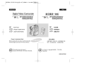
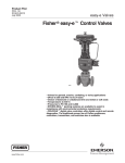
Product Bulletin ENVIRO-SEAL Bellows Seal 59.1:070 December 2012 D101641X012 Fisherr ENVIRO-SEAL™ Bellows Seal Bonnets ENVIRO-SEAL bellows seal bonnets improve sealing capabilities of Fisher valves and provide long life for applications where emissions escaping from a valve stem seal to the atmosphere cannot be tolerated. This excellent stem sealing system is available for Fisher easy-et valves (see the specifications table for information on valve designs and sizes). UPPER BUSHING PACKING Corrosion resistance is excellent--the bellows is available in either N06625 or N06022, and the bellows is protected against direct impingement by the flow stream. The mechanically formed bellows provides high operating reliability and extended cycle life, and the large annular area around the bellows optimizes warming by the process fluid. ANTI-ROTATOR PIN PURGE-MONITORING CONNECTION Features BELLOWS Excellent Sealing Capabilities are Factory Tested–Every bellows seal is tested before leaving the factory. Each bellows is mass spectrometer tested to 1 X 10⁻⁶ cubic centimeters per second of helium. Long Cycle Life–Cycle lives in excess of those shown in tables 1, 2, 3, and 4 can be achieved with proper use and maintenance. Easy Installation in Existing Valves–All parts needed to install the system in existing valves are available in a convenient kit. Rugged Construction–An anti-rotator pin helps prevent accidental twisting and subsequent damage and helps prevent stem blow out. A full-length shroud protects the bellows against damage during handling, inspection, or maintenance. See the following figure. PROTECTIVE SHROUD Purging/Monitoring Connections are Standard–Two connections above the bellows allow for purging or monitoring of bellows integrity. www.Fisher.com VALVE PLUG CONNECTION VALVE PLUG W5800-2 ENVIRO-SEAL Bellows Detail (Mounted on easy-e VALVE) Product Bulletin ENVIRO-SEAL Bellows Seal 59.1:070 December 2012 D101641X012 Specifications Applicable Valve Designs NPS 1/2 through 4 Fisher CL125 through 600 Jeasy-e valves (for example, EAT, EZ, ETR, etc.),JYD, and JYS valves Cycle Life See tables 1, 2, 3, and 4 and the Cycle Life section. The bellows is available in Jone-ply or Jtwo-ply construction for higher pressures and longer cycle life Pressures and Temperatures(1) See tables 5 and 6. Do not exceed the pressure-temperature rating of the valve or the maximum temperature of the packing and gaskets Factory Testing Specification Every bellows is tested to 1 X 10⁻⁶ cubic centimeters per second of helium Bellows Seal Travel (Also See Cycle Life Section) See table 7 Construction Materials See table 10 ENVIRO-SEAL Packing: See Bulletin 59.1:061 ENVIRO-SEAL Packing Systems for Sliding-Stem Valves Bellows Gasket: Graphite Laminate -254 to 593_C (-425 to 1100_F) Valve Components: See the valve bulletin Applicable Stem and Yoke Boss Diameters See table 11 Maximum Flow Coefficients See table 7 Bellows Spring Rate Negligible for actuator sizing and selection purposes Bellows Effective Area When sizing an actuator, use the bellows effective area instead of the valve stem area NPS 1/2 through 2 Valves: 2.28 cm2 (0.353 square inches) NPS 3 and 4 Valves: 8.65 cm2 (1.340 square inches) Dimensions Material Temperature Capabilities(1) Standard Packing: See figure 2 Material In-Body Process Temperature Limits(2) PTFE and PTFE/ Composition -46 to 427_C (-50 to 800_F) Temperature Limits of the Packing Material -40 to 232_C (-40 to 450_F) Graphite Ribbon/ Filament -46 to 593_C (-50 to 1100_F) -18 to 538_C(3) (0 to 1000_F(3)) Options JRetrofit kits for installation in existing valves. JENVIRO-SEAL packing systems (figure 1) with PTFE, Graphite ULF, or Duplex packing materials; see Bulletin 59.1:061 1. The pressure-temperature limits in this bulletin, in the valve bulletin, and any applicable code or standard limitation, should not be exceeded. 2. These in-body process temperatures assume an outside, ambient temperature of 21_C (70_F). 3. Limit to 371_C (700_F) on oxidizing service. 2 Product Bulletin ENVIRO-SEAL Bellows Seal 59.1:070 December 2012 D101641X012 Cycle Life ENVIRO-SEAL bellows are normally sold with the travel limited for optimum cycle life performance. Bellows may be operated at full valve travel at reduced cycle life. Bellows seal service life is affected by several factors, including pressure, temperature, and travel. The cycle life values listed in tables 1, 2, 3, and 4 are determined from experimental data and reflect a 99% confidence factor. These cycle life estimates do not include effects from vibration in the piping system. Table 1. Estimated Cycle Life for N06625 Bellows(1) at 10.3 Bar (150 Psig) and 38_C (100_F) VALVE SIZE, NPS 1/2, 3/4, 1, & 1-1/2 2 3 4 BELLOWS SEAL TRAVEL mm Inch mm Inch mm Inch mm Inch mm Inch mm Inch 3.6 0.14 4.6 0.19 6.4 0.28 9.7 0.38 14.2 0.56 19.1 0.75 1 Ply 8,000,000 4,000,000 1,400,000 550,000 150,000 2 Ply 10,000,000 10,000,000 2,300,000 800,000 160,000 50,000 50,000 mm Inch mm Inch mm Inch mm Inch mm Inch mm Inch 5.3 0.21 7.1 0.28 10.7 0.42 14.2 0.56 22.2 0.88 28.6 1.12 1 Ply 8,000,000 4,000,000 1,400,000 550,000 150,000 2 Ply 10,000,000 10,000,000 2,300,000 800,000 160,000 50,000 50,000 mm Inch mm Inch mm Inch mm Inch mm Inch mm Inch 6.4 0.28 9.5 0.38 26.0 0.56 19.1 0.75 28.6 1.12 38.1 1.50 1 Ply 1,000,000 1,000,000 700,000 450,000 300,000 2 Ply 10,000,000 10,000,000 5,000,000 2,500,000 1,000,000 100,000 350,000 mm Inch mm Inch mm Inch mm Inch mm Inch mm Inch 9.5 0.38 12.7 0.5 19.1 0.75 28.6 1.12 38.1 1.50 50.8 2.00 1 Ply 1,000,000 700,000 450,000 300,000 100,000 50,000 2 Ply 10,000,000 5,000,000 2,500,000 1,000,000 350,000 150,000 1. See the Cycle Life section in this bulletin for more information on bellows travel. Table 2. Estimated Cycle Life for N06625 Bellows(1) at Maximum Pressure and 316_C (600_F) VALVE SIZE, NPS 1/2, 3/4, 1, & 1-1/2 2 3 4 BELLOWS SEAL TRAVEL mm Inch mm Inch mm Inch mm Inch mm Inch mm Inch 3.6 0.14 4.6 0.19 6.4 0.28 9.7 0.38 14.2 0.56 19.1 0.75 1 Ply 100,000 80,000 50,000 30,000 12,000 2 Ply 100,000 90,000 50,000 30,000 12,000 7,000 7,000 mm Inch mm Inch mm Inch mm Inch mm Inch mm Inch 5.3 0.21 7.1 0.28 10.7 0.42 14.2 0.56 22.2 0.88 28.6 1.12 1 Ply 100,000 80,000 50,000 30,000 12,000 2 Ply 100,000 90,000 50,000 30,000 12,000 7,000 7,000 mm Inch mm Inch mm Inch mm Inch mm Inch mm Inch 6.4 0.28 9.5 0.38 26.0 0.56 19.1 0.75 28.6 1.12 38.1 1.50 1 Ply 45,000 45,000 34,000 24,000 18,000 2 Ply 50,000 50,000 41,000 34,000 24,000 12,000 12,000 mm Inch mm Inch mm Inch mm Inch mm Inch mm Inch 9.5 0.38 12.7 0.5 19.1 0.75 28.6 1.12 38.1 1.50 50.8 2.00 1 Ply 45,000 34,000 24,000 18,000 12,000 7,000 2 Ply 50,000 41,000 34,000 24,000 12,000 7,000 1. See the Cycle Life section in this bulletin for more information on bellows travel. 3 Product Bulletin ENVIRO-SEAL Bellows Seal 59.1:070 December 2012 D101641X012 Table 3. Estimated Cycle Life for N06022 Bellows(1) at 10.3 Bar (150 Psig) and 38_C (100_F) VALVE SIZE, NPS 1/2, 3/4, 1, & 1-1/2 2 3 4 BELLOWS SEAL TRAVEL mm Inch mm Inch mm Inch mm Inch mm Inch mm Inch 3.6 0.14 4.6 0.19 6.4 0.28 9.7 0.38 14.2 0.56 19.1 0.75 1 Ply 8,000,000 4,000,000 1,200,000 500,000 110,000 2 Ply 10,000,000 10,000,000 2,000,000 650,000 140,000 40,000 40,000 mm Inch mm Inch mm Inch mm Inch mm Inch mm Inch 5.3 0.21 7.1 0.28 10.7 0.42 14.2 0.56 22.2 0.88 28.6 1.12 1 Ply 8,000,000 4,000,000 1,200,000 500,000 110,000 2 Ply 10,000,000 10,000,000 2,000,000 650,000 140,000 40,000 40,000 mm Inch mm Inch mm Inch mm Inch mm Inch mm Inch 6.4 0.28 9.5 0.38 26.0 0.56 19.1 0.75 28.6 1.12 38.1 1.50 1 Ply 1,000,000 1,000,000 700,000 450,000 300,000 2 Ply 10,000,000 10,000,000 5,000,000 2,000,000 900,000 100,000 300,000 mm Inch mm Inch mm Inch mm Inch mm Inch mm Inch 9.5 0.38 12.7 0.5 19.1 0.75 28.6 1.12 38.1 1.50 50.8 2.00 1 Ply 1,000,000 700,000 450,000 300,000 100,000 50,000 2 Ply 10,000,000 5,000,000 2,000,000 900,000 300,000 130,000 1. See the Cycle Life section in this bulletin for more information on bellows travel. Table 4. Estimated Cycle Life for N06022 Bellows(1) at Maximum Pressure and 316_C (600_F) VALVE SIZE, NPS 1/2, 3/4, 1, & 1-1/2 2 3 4 BELLOWS SEAL TRAVEL mm Inch mm Inch mm Inch mm Inch mm Inch mm Inch 3.6 0.14 4.6 0.19 6.4 0.28 9.7 0.38 14.2 0.56 19.1 0.75 1 Ply 90,000 80,000 50,000 30,000 12,000 2 Ply 100,000 90,000 50,000 30,000 12,000 6,000 mm Inch mm Inch mm Inch mm Inch mm Inch mm Inch 5.3 0.21 7.1 0.28 10.7 0.42 14.2 0.56 22.2 0.88 28.6 1.12 1 Ply 90,000 80,000 50,000 30,000 12,000 2 Ply 100,000 90,000 50,000 30,000 12,000 6,000 6,000 mm Inch mm Inch mm Inch mm Inch mm Inch mm Inch 6.4 0.28 9.5 0.38 26.0 0.56 19.1 0.75 28.6 1.12 38.1 1.50 1 Ply 40,000 40,000 34,000 24,000 18,000 2 Ply 50,000 50,000 40,000 31,000 23,000 12,000 12,000 mm Inch mm Inch mm Inch mm Inch mm Inch mm Inch 9.5 0.38 12.7 0.5 19.1 0.75 28.6 1.12 38.1 1.50 50.8 2.00 1 Ply 40,000 34,000 24,000 18,000 12,000 7,000 2 Ply 50,000 40,000 31,000 23,000 12,000 7,000 1. See the Cycle Life section in this bulletin for more information on bellows travel. 4 6,000 Product Bulletin ENVIRO-SEAL Bellows Seal 59.1:070 December 2012 D101641X012 Table 5. Pressure-Temperature Rating for N06625 Bellows VALVE SIZE, NPS PRESSURE, BAR Temp., _C 38 93 149 204 260 316 371 427 1/2, 3/4, 1, 1-1/2, and 2 1 Ply 2 Ply 37.9 68.9 34.9 63.4 33.0 60.0 31.1 56.5 29.6 53.8 28.5 51.7 17.1 50.3 27.3 49.6 3&4 1 Ply 2 Ply 23.9 43.1 21.6 39.6 20.4 37.5 19.2 35.3 18.3 33.6 17.6 32.3 17.1 31.4 16.9 31.0 Temp., _F 100 200 300 400 500 600 700 800 1/2, 3/4, 1, 1-1/2, and 2 1 Ply 2 Ply 550 1000 506 920 479 870 451 820 429 780 413 750 402 730 396 720 3&4 1 Ply 2 Ply 346 625 313 575 296 544 279 512 265 488 255 469 248 456 245 450 VALVE SIZE, NPS PRESSURE, PSIG Table 6. Pressure-Temperature Rating for N06022 Bellows VALVE SIZE, NPS PRESSURE, BAR Temp., _C 38 93 149 204 260 316 371 427 1/2, 3/4, 1, 1-1/2, and 2 1 Ply 2 Ply 37.9 68.9 36.8 66.8 36.0 65.5 34.9 63.4 33.4 60.6 32.6 59.3 31.5 57.2 30.3 55.1 3&4 1 Ply 2 Ply 23.9 43.1 22.7 41.8 22.3 40.9 21.6 39.6 20.6 37.9 20.1 37.0 19.4 35.8 18.7 34.5 Temp., _F 100 200 300 400 500 600 700 800 1/2, 3/4, 1, 1-1/2, and 2 1 Ply 2 Ply 550 1000 534 970 523 950 506 920 484 880 473 860 457 830 440 800 3&4 1 Ply 2 Ply 340 625 330 606 323 594 313 575 299 550 292 537 282 519 272 500 VALVE SIZE, NPS PRESSURE, PSIG Figure 1. Typical ENVIRO-SEAL Packing Systems PACKING BOX STUDS PACKING BOX STUDS SPRINGS SPRINGS FOLLOWER ANTIEXTRUSION RING PACKING RING PACKING LANTERN RING 39B4611-A A6290 5 Product Bulletin ENVIRO-SEAL Bellows Seal 59.1:070 December 2012 D101641X012 Table 7. Flow Coefficients with ENVIRO-SEAL Bellows Seal and easy-e Valves VALVE DESIGN BELLOWS SEAL TRAVEL FULL-SIZE TRIM VALVE SIZE, NPS mm Inch Quick Opening Linear 1 1-1/2 2 3 4 14.2 14.2 22.2(1) 28.6 38.1(2) 0.56 0.56 0.88(1) 1.125 1.50(2) 21.5 40.4 74.7 152 243 17.8 32.5 65.1 126 192 1 1-1/2 2 3 4 14.2 14.2 22.2(1) 28.6 38.1(2) 0.56 0.56 0.88(1) 1.125 1.50(2) 641 1300 2390 4740 7990 559 1090 2130 4130 6680 1/2 3/4 1 1-1/2 2 3 4 14.2 14.2 14.2 14.2 22.2(1) 28.6 38.1(2) 0.56 0.56 0.56 0.56 0.88(1) 1.125 1.50(2) 6.53 14.2 21.2 38.0 67.2 140 228 ----16.8 28.4 60.6 117 174 1/2 3/4 1 1.5 2 3 4 14.2 14.2 14.2 14.2 22.2(1) 28.6 38.1(2) 0.56 0.56 0.56 0.56 0.88(1) 1.125 1.50(2) 206 415 688 1325 2410 4780 8000 ----565 967 2100 4100 6170 1/2 3/4 1 1.5 2 3 4 14.2 14.2 14.2 14.2 22.2(1) 28.6 38.1(2) 0.56 0.56 0.56 0.56 0.88(1) 1.125 1.50(2) 4.44 9.72 16.8 33.6 58.5 127 221 ----11.6 27.5 46.2 93.4 168 1/2 3/4 1 1-1/2 2 3 4 14.2 14.2 14.2 14.2 22.2(1) 28.6 38.1(2) 0.56 0.56 0.56 0.56 0.88(1) 1.125 1.50(2) 168 341 475 1250 2140 4490 7940 ----375 921 1630 3460 5860 RESTRICTED TRIM Equal Percentage Quick Opening Linear Equal Percentage 9.37 21.0 31.4 81.5 148 --26.8 31.2 91.9 130 --22.5 33.3 102 113 --11.1 24.3 70.7 112 325 695 1070 2690 5000 --990 1120 3170 4750 --760 1110 3490 4220 --357 783 2370 4040 ----11.3 20.4 30.9 73.1 125 ------30.0 39.4 115 183 ------19.5 30.9 88.8 139 ------10.0 20.8 67.5 121 ----367 679 1090 2540 4250 ------992 1350 3990 6280 ------659 1050 3060 4910 ------334 710 2320 4230 ----9.15 13.1 38.8 73.4 118 ------19.0 17.9 88.4 86.7 ------12.0 15.7 80.4 86.8 ------10.0 15.9 71.5 72.7 ----299 417 1330 2400 3770 ------727 687 3120 2910 ------380 599 2783 2979 ------302 605 2450 2570 Cv ED, EDR, ET, and ETR (Flow Down) Cg Cv ES (Flow Up) Cg Cv EZ (Flow Up) Cg Note: Bellows seal travel is 75% of maximum rated valve travel. 1. 19.1 mm (0.75 inch) travel for restricted trim. 2. 28.6 mm (1.125 inch) travel for restricted trim. 6 Product Bulletin ENVIRO-SEAL Bellows Seal 59.1:070 December 2012 D101641X012 Table 8. Dimensions for easy-e Valves easy-e VALVES VALVE SIZE, NPS Stem Diameter Inch mm Inch 9.5 3/8 320 12.59 1-1/2 9.5 3/8 317 12.47 2 12.7 1/2 383 15.09 3 12.7 1/2 517 20.34 4 12.7 1/2 541 21.28 1/2, 3/4, & 1 With New Valves Table 9. Dimensions for easy-e Valves VALVE STEM DIAMETER mm Inch 9.5 12.7 D mm ACTUATOR TYPE ACTUATOR SIZE 657 E 1. Refer to the valve bulletin for ordering information. mm Inch 30 34 440 498 17.31 19.62 667 30 34 478 573 18.81 22.56 657 40 45 46 548 659 656 21.56 25.94 25.81 667 40 45 46 594 768 748 23.38 30.25 29.44 3/8 1/2 2. Also refer to the specifications. Review the information under each specification and in the referenced tables; write down your choice whenever there is a selection to be made. Figure 2. Dimensions for easy-e Valves (also see tables 8 and 9) Ordering Information When ordering, specify: E For Existing Valves 1. Process fluid 2. Process fluid temperature 3. Maximum valve inlet pressures 1/4-NPT PURGEMONITORING CONNECTIONS 4. Maximum valve pressure drops D 5. Valve design (ED, YD, etc.), size, and class 6. Valve stem diameter 7. Refer to the specifications. Review the information under each specification and in the referenced tables; write down your choice whenever there is a selection to be made. A5696 7 Product Bulletin ENVIRO-SEAL Bellows Seal 59.1:070 December 2012 D101641X012 Table 10. Construction Materials PART easy-e VALVES Bonnet WCC steel or CF3M (316L stainless steel) Bellows Seal Assembly (Bellows / Other Wetted Parts) N06625 / S31603 (316L stainless steel) or N06022 / N06022 Upper Bushing S31600 (316 stainless steel), R30006, Chrome-coated S31600, PTFE-lined S31600, or N10276/PTFE-glass Bonnet Gaskets Graphite laminate/stainless steel Packing PTFE V-ring, PTFE/composition, graphite ribbon/filament, or PTFE or ENVIRO-SEAL Graphite ULF packing system Packing Box Ring and Lantern Ring S31600 (316 stainless steel) or N10276 Packing Flange, Studs, and Nuts Steel, 316 stainless steel, or N10276 Valve Components See valve bulletin Table 11. Applicable Yoke Boss and Stem Diameters easy-e VALVES Yoke Boss Diameter VALVE SIZE, NPS Stem Thread Diameter(1) Valve Stem Diameter(2) mm Inch mm Inch mm Inch 1/2, 3/4, 1, & 1-1/2 54 2-1/8 9.5 3/8 12.7 1/2 2 71 2-13/16 12.7 1/2 12.7 1/2 3&4 71 2-13/16 12.7 1/2 25.4 1 1. This is the diameter at the actuator stem connector. 2. This is the diameter where the stem passes through the packing. Neither Emerson, Emerson Process Management, nor any of their affiliated entities assumes responsibility for the selection, use or maintenance of any product. Responsibility for proper selection, use, and maintenance of any product remains solely with the purchaser and end user. Fisher, ENVIRO-SEAL, and easy-e are marks owned by one of the companies in the Emerson Process Management business unit of Emerson Electric Co. Emerson Process Management, Emerson, and the Emerson logo are trademarks and service marks of Emerson Electric Co. All other marks are the property of their respective owners. The contents of this publication are presented for informational purposes only, and while every effort has been made to ensure their accuracy, they are not to be construed as warranties or guarantees, express or implied, regarding the products or services described herein or their use or applicability. All sales are governed by our terms and conditions, which are available upon request. We reserve the right to modify or improve the designs or specifications of such products at any time without notice. Emerson Process Management Marshalltown, Iowa 50158 USA Sorocaba, 18087 Brazil Chatham, Kent ME4 4QZ UK Dubai, United Arab Emirates Singapore 128461 Singapore www.Fisher.com E 8 1991, 2012 Fisher Controls International LLC. All rights reserved.