1
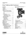
Product Bulletin
3660 and 3661 Positioners
62.1:3660
May 2012
D101407X012
FisherR 3660 and 3661 Positioners
Fisher 3660 pneumatic and 3661 electro‐pneumatic
single‐acting positioners are used with various
actuators on sliding‐stem valves for throttling
applications. These rugged positioners provide a valve
position proportional to a pneumatic input or a
standard millampere DC input signal received from a
control device.
Features
n Accurate, Efficient, Vibration‐Resistant
Operation—Positioner design provides accurate,
fast‐responding instruments able to withstand the
vibrations of most plant environments. Low
steady‐state air consumption contributes to
efficient operation.
n Variable Gain—Easily adjustable gain and damping
adjustments fine tune the positioner stability to
specific application requirements.
Fisher 3660 Positioner with
Baumannt Valve and Actuator
n Versatility—Positioner accepts a standard
pneumatic input signal (3660) or a standard
milliampere DC input signal (3661) from a control
device. This positioner provides split range
capabilities and adjustable zero and spans.
n Fewer Spare Parts Required—Most of the parts for
3660 and 3661 positioners are interchangeable,
requiring fewer spare parts to support these
positioners.
n Rugged Construction—The case and cover are
designed to withstand mechanical vibration and
rough handling.
www.Fisher.com
W7174
n Easy Positioner Adjustments—Zero and span
adjustments can be made with the cover in place.
n Control Valve Diagnostic Testing Capability—To
support diagnostic testing of
valve/actuator/positioner packages with the
FlowScannert valve diagnostic system,
connectors, piping, and other hardware can be
installed between the 3660 or 3661 positioner and
the actuator. A typical connector installation is
shown in figure 4.
Product Bulletin
3660 and 3661 Positioners
62.1:3660
May 2012
D101407X012
Specifications
Positioner Adjustments
Available Configuration
Span: Adjustable from 19 mm to 50 mm
(0.75 to 2 inches) stem travel
Zero: 0 to 100%
Gain: 0.5 to 6% PB (proportional band)(3).
Output Volume Damping: Loop dynamic response
adjustment
3660: Single‐acting pneumatic valve positioner
3661: Single‐acting electro‐pneumatic valve
positioner
Input Signal
3660:
J0.2 to 1.0 bar (3 to 15 psig), J0.4 to 2.0 bar
(6 to 30 psig), or JSplit range, see table 2
3661:
J4‐20 mA DC constant current with 30 VDC
maximum compliance voltage JSplit range is also
available, see table 2
Delivery Capacity(4):
1.4 Bar (20 Psig) Supply: 4.3 normal m3/hour
(150 scfh)
2.4 Bar (35 Psig) Supply: 6.6 normal m3/hour
(230 scfh)
Exhaust Capacity(4):
1.4 Bar (20 Psig) Supply: 4.8 normal m3/hour
(170 scfh)
2.4 Bar(35 Psig) Supply: 7.4 normal m3/hour
(260 scfh)
Equivalent Circuit (3661)
120 ohms shunted by three 5.6 V zener diodes
Output Signal
Steady‐State Air Consumption(4,5)
Type: Pneumatic pressure as required by the actuator
up to full supply pressure
Action: JDirect (increasing input signal increases
positioner output), JReverse (increasing input signal
decreases positioner output)
3660: 0.17 normal m3/hour (6.0 scfh) at
1.4 bar (20 psig) supply pressure.
0.22 normal m3/hour (7.9 scfh) at 2.4 bar (35 psig)
supply pressure
3661: 0.24 normal m3/hour (8.8 scfh) at 1.4 bar
(20 psig) supply pressure. 0.33 normal m3/hour
(12.3 scfh) at 2.4 bar (35 psig) supply pressure
Supply Pressure(1)
Recommended: 10% above actuator requirements
Maximum: 6.2 bar (90 psig) or pressure rating of
actuator, whichever is lower
Operating Influences
Supply Pressure: 69 mbar (1 psig) change in supply
pressure changes the actuator stem position less than
0.16%(6) of the travel
Medium: air
3660 and 3661 are not compatible with natural gas as
the supply medium
3660 without Pressure Gauges: -40 to 121°C
(-40 to 250°F)
3660 with Pressure Gauges: -40 to 82°C
(-40 to 180°F)
Performance
Independent Linearity: ±1% of output span.
Hysteresis: 0.5% of output span(2).
Deadband: 0.1% of input span.
3661 with or without Pressure Gauges: -40 to 82°C
(-40 to 180°F)
Electromagnetic Compatibility for 3661
electro‐pneumatic positioner:
Meets EN 61326‐1 (First Edition)
Immunity—Industrial locations per Table 2 of
the EN 61326‐1 standard. Performance is
shown in table 1 below.
Emissions—Class A
ISM equipment rating: Group 1, Class A
Hazardous Area Classification for 3660
3660 pneumatic positioners comply with the
requirements of ATEX Group II Category 2 Gas and
Dust
‐ continued ‐
2
Operative Temperature Limits(1)
Product Bulletin
3660 and 3661 Positioners
62.1:3660
May 2012
D101407X012
Specifications (continued)
Hazardous Area Classification for 3661
CSA—Intrinsically Safe, Type n, Non‐incendive
FM—Intrinsically Safe, Type n, Non‐incendive
ATEX—Intrinsically Safe, Type n
(Gas Atmospheres Only)
IECEx—Intrinsically Safe, Type n
(Gas Atmospheres Only)
Refer to tables 6, 7, 8, and 9 for additional
information
Conduit Connection for 3661
Housing Classification for 3661
CSA—Type 3 Encl.
FM—NEMA 3, IP54
ATEX—IP44
IECEx—IP44
Mounting orientation requires vent location to be
below horizontal
Construction Materials
1/2 NPT (M20 or PG13 adaptors optional)
Vent Connection
1/4 NPT internal
Maximum Valve Stem Travel
50 mm (2 inch); adjustable to obtain lesser travel with
standard input signal—minimum 19 mm (0.75 inch)
See table 4
Approximate Weight
3660: 2.6 pounds (1.2 kg)
3661: 3.0 pounds (1.4 kg)
Options
Mounting
The positioner can be mounted in one of four
different configurations. See figure 1.
3660:
JInstrument and output pressure gauges,
JIntegrally mounted bypass valve
Pressure Connections
1/4 NPT internal
3661: Output pressure gauge
3660 and 3661: Connectors for diagnostic testing
Jstainless steel or Jbrass
NOTE: Specialized instrument terms are defined in ANSI/ISA Standard 51.1 - Process Instrument Terminology.
1. The pressure/temperature limits in this bulletin and any applicable standard or code limitation should not be exceeded.
2. Hysteresis value at a gain setting of 1/2 turn.
3. Adjusting the gain (PB) adjustment will change the nozzle flapper relationship. This nozzle flapper change affects the actuator/positioner response time.
4. Normal m3/hr‐‐normal cubic meters per hour (0_C and 1.01325 bar absolute). Scfh‐‐standard cubic feet per hour (60_F and 14.7 psia).
5. Air consumption at a gain setting of 1/2 turn.
6. At supply pressure of 2.4 bar (35 psig).
Table 1. Fisher 3661 Electro‐Pneumatic Positioner EMC Summary Results—Immunity
Port
Enclosure
Phenomenon
Electrostatic discharge
(ESD)
IEC 61000‐4‐2
Radiated EM field
IEC 61000‐4‐3
Rated power frequency
magnetic field
Burst
I/O signal/control
Basic Standard
Test Level
4 kV contact
8 kV air
80 to 1000 MHz @ 10V/m with 1 kHz AM at 80%
1400 to 2000 MHz @ 3V/m with 1 kHz AM at 80%
2000 to 2700 MHz @ 1V/m with 1 kHz AM at 80%
Performance Criteria(1)
A
A
IEC 61000‐4‐8
60 A/m at 50 Hz
A
A
IEC 61000‐4‐4
1 kV
Surge
IEC 61000‐4‐5
1 kV (line to ground only, each)
B
Conducted RF
IEC 61000‐4‐6
150 kHz to 80 MHz at 3 Vrms
A
Specification limit = ±1% of span
1. A = No degradation during testing. B = Temporary degradation during testing, but is self‐recovering.
3
Product Bulletin
3660 and 3661 Positioners
62.1:3660
May 2012
D101407X012
Figure 1. Mounting Configurations (see table 3 for Positioner Action and Signals)
OUTPUT
OUTPUT
INPUT
SIGNAL
AIR SUPPLY
2
1
INPUT SIGNAL
PILOT SHAFT
AIR SUPPLY
FEEDBACK
PLATE
ACTUATOR: AIR‐TO‐RETRACT
POSITIONER ACTION: REVERSE
(INCREASING INPUT SIGNAL DECREASES
OUTPUT PRESSURE TO ACTUATOR)
ACTUATOR: AIR‐TO‐RETRACT
POSITIONER ACTION: DIRECT
(INCREASING INPUT SIGNAL INCREASES
OUTPUT PRESSURE TO ACTUATOR)
OUTPUT
OUTPUT
AIR SUPPLY
INPUT
SIGNAL
2
1
AIR SUPPLY
INPUT SIGNAL
ACTUATOR: AIR‐TO‐EXTEND
POSITIONER ACTION: REVERSE
(INCREASING INPUT SIGNAL DECREASES
OUTPUT PRESSURE TO ACTUATOR)
ACTUATOR: AIR‐TO‐EXTEND
POSITIONER ACTION: DIRECT
(INCREASING INPUT SIGNAL INCREASES
OUTPUT PRESSURE TO ACTUATOR)
Notes:
1 When mounting on Baumann actuators, install feedback plate so lip is up. Install feedback lever arm assembly so pilot shaft is on
top of the feedback plate.
2 When mounting on Baumann actuators, install feedback plate so lip is down. Install feedback lever arm assembly so pilot shaft is
underneath the feedback plate.
17B9106‐B
17B9105‐B
38B0195‐B
A4035‐2
4
Product Bulletin
3660 and 3661 Positioners
62.1:3660
May 2012
D101407X012
Table 2. Standard and Split Range Capabilities
POSITIONER
3660
3660
Split
0.2 to 1.0 bar
(3 to 15 Psig)
Input Signal
0.4 to 2.0 bar
(6 to 30 Psig)
Input Signal
Bar
Psig
Psig
3661
4 to 20 mA DC Input Signal
Bar
One Way
1:1
0.2 to 1.0
3 to 15
6 to 30
0.4 to 2.0
4 to 20
Two Way
2:1
0.2 to 0.6
0.6 to 1.0
3 to 9
9 to 15
6 to 18
18 to 30
0.4 to 1.2
1.2 to 2.0
4 to 12
12 to 20
0.2 to 0.5
0.5 to 0.8
0.8 to 1.0
0.2 to 0.4
0.4 to 0.6
0.6 to 0.8
0.8 to 1.0
3 to 7
7 to 11
11 to 15
3 to 6
6 to 9
9 to 12
12 to 15
6 to 14
14 to 22
22 to 30
6 to 12
12 to 18
18 to 24
24 to 30
0.4 to 1.0
1.0 to 1.6
1.6 to 2.0
0.4 to 0.8
0.8 to 1.2
1.2 to 1.6
1.6 to 2.0
4 to 9.33
9.33 to 14.66
14.66 to 20
4 to 8
8 to 12
12 to 16
16 to 20
Three Way
3:1
Four Way
4:1
Table 3. Positioner Input Signal, Action, and Output
Signal
Input Signal
For split range signal refer to table 2
PART
Positioner Output
Direct
0.2 to 1.0 bar (3 to 15 psig)
0.4 to 2.0 bar (6 to 30 psig)
4 to 20 mA
Reverse
1.0 to 0.2 bar (15 to 3 psig)
2.0 to 0.4 bar (30 to 6 psig)
20 to 4 mA
Table 4. Construction Materials
Up to 6.2 bar
(90 psig)
MATERIAL
Standard
Optional
Case and Cover
Aluminum
---
Feedback Lever
Assembly
Stainless Steel
---
Range Spring
N09902
---
Input Module
Diaphragm Relay
Gasket
O‐Ring
ECO
EPDM
Silicon Rubber
Ethylene/Propylene
---
Nozzle
Aluminum
---
Flapper
Aluminum
---
Relay Metal Parts
Aluminum and
Stainless Steel
---
Gauges
Brass and Plastic
---
All Fasteners
Stainless Steel
Exterior Tubing
and Fitting
Copper/Brass
Connectors for
Diagnostic Testing
Stainless Steel or Brass
Stainless Steel
---
5
Product Bulletin
3660 and 3661 Positioners
62.1:3660
May 2012
D101407X012
Principle of Operation
once again in equilibrium but at a higher instrument
pressure, a slightly different flapper position, and a
new actuator stem position.
Refer to figure 2 for operational schematic.
A decrease in instrument pressure decreases nozzle
pressure, which allows the relay to bleed off actuator
loading pressure.
The instrument pressure acts on the input module,
which controls the flapper‐nozzle system of the relay.
Supply pressure is applied to the relay, and the output
pressure of the relay is supplied to the control valve
actuator.
Operation of a reverse‐acting positioner is similar
except that the flapper position is reversed from that
shown in figure 2. The reversed position uses the
alternate flapper pivot point so that increases in
instrument pressure rotate the flapper away from the
nozzle to reduce nozzle pressure.
For a direct‐acting positioner, increases in instrument
pressure causes the input module to pivot the beam.
The beam pivots the flapper and restricts the nozzle.
The nozzle pressure increases and causes the relay
assembly to increase output pressure to the actuator.
With a direct‐acting actuator, this increased pressure
moves the actuator stem downward. Stem movement
is fed back to the beam by means of a feedback lever
and range spring, which cause the flapper to pivot
slightly away from the nozzle to prevent any further
increases in relay output pressure. The positioner is
With a 3661 electro‐pneumatic positioner, the
electro‐pneumatic converter provides a 0.2 to 1.0 bar
(3 to 15 psig) output pressure proportional to the
4‐20 mA input signal. The 0.2 to 1.0 bar (3 to 15 psig)
output pressure becomes the input signal pressure to
the input module.
FLAPPER
Figure 2. Operational Schematic
DIRECT
ACTING
PIVOT
OUTPUT
RANGE
SPRING
A
FEEDBACK
PLATE
SECTION A‐A
GAIN ADJ
SUPPLY
INPUT
MODULE
RANGE
SPRING
A
PIVOT
BEAM
FEEDBACK
LEVER
REVERSE
ACTING PIVOT
RELAY
A
PILOT
SHAFT
NOZZLE
BEAM
RELAY
GAIN ADJ
A
SUPPLY
PIVOT
FISHER 3660 POSITIONER
INPUT
MODULE
I/P CONVERTER
31B3960‐C
B2152‐4
6
INPUT SIGNAL
FISHER 3661 POSITIONER
Product Bulletin
3660 and 3661 Positioners
62.1:3660
May 2012
D101407X012
Figure 3. Positioner Dimensions and Connections (see table 5 for the X dimension)
ACTUATOR POST
CENTERLINE
191.2
(7.53)
93
49
(3.66)
(1.93)
34.32
(1.35)
49.2
(1.94)
67.5
(2.66)
0.5
(0.02)
DIM X
1/4 NPT
SUPPLY
CONNECTION
ACTUATOR
CENTERLINE
30
(1.18)
122.3
(4.81)
30
(1.18)
21.5
(0.85)
1/4 NPT
INSTRUMENT
CONNECTION
ACTUATOR POST
CENTERLINE
142.2
(5.60)
34.32
(1.35)
49.2
(1.94)
67.5
(2.66)
93
(3.66)
DIM X
1/4 NPT
SUPPLY
CONNECTION
27.5
(1.08)
1/4 NPT
OUTPUT
CONNECTION
ACTUATOR
CENTERLINE
30
(1.18)
122.3
(4.81)
30
(1.18)
21.5
(0.85)
1/2 NPT
3661 I/P
ONLY
31B3959‐C
C0686‐3
1/4 NPT
INSTRUMENT
CONNECTION
1/4 NPT
OUTPUT
CONNECTION
mm
(INCH)
7
Product Bulletin
3660 and 3661 Positioners
62.1:3660
May 2012
D101407X012
Ordering Information
Table 5. Dimension X for figure 3
ACTUATOR CENTERLINE TO POSITIONER
Type
Size
657/667
1250
3024S
Baumann
GX
X
mm
Inch
30
34
40
45/46
50/60
92.2
95.3
104.9
108.0
128.5
3.63
3.75
4.13
4.25
5.06
225
450
675
1.21
1.31
1.41
16in2
32in2
54in2
70in2
86.0
86.0
110.0
83.5
87.5
87.5
53.8
71.4
71.4
71.4
3.39
3.39
4.33
3.29
3.44
3.44
2.12
2.81
2.81
2.81
225
750
1200
81.0
81.0
81.0
3.19
3.19
3.19
Application
When ordering, specify:
1. Type number
2. Input signal range: pneumatic or milliampere
3. Maximum supply pressure available
4. Valve plug travel: actuator type and size
5. Stroking time requirements, if critical
6. Ambient temperature range
Installation
The supply pressure medium should be clean, dry,
filtered air. If the supply source is capable of exceeding
the maximum actuator operating pressure or
positioner supply pressure, appropriate steps must be
taken during installation to protect the positioner and
all connected equipment against overpressure.
Overall dimensions and connections are shown in
figure 3 and table 5.
8
7. Direct or reverse acting
8. Supply pressure regulator, gauges, and bypass, if
required
9. Hazardous area classification (3661)
10. Connectors for diagnostic testing, if required
Product Bulletin
3660 and 3661 Positioners
62.1:3660
May 2012
D101407X012
Figure 4. FlowScanner Diagnostic System Connections
BODY PROTECTOR
BODY
PIPE BUSHING
4 IN PIPE NIPPLE
PIPE TEE
3660 POSITIONER
12B8052‐A
A6084
1 IN PIPE NIPPLE
FISHER 3660 POSITIONER
BODY PROTECTOR
1 IN PIPE NIPPLE
BODY
PIPE BUSHING
4 IN PIPE NIPPLE
PIPE NIPPLE
3661 POSITIONER
12B8053‐A
A6085
FISHER 3661 POSITIONER
9
Product Bulletin
3660 and 3661 Positioners
62.1:3660
May 2012
D101407X012
Table 6. Fisher 3661 Positioner Hazardous Area Classifications—CSA (Canada)
Certification Body
Certification Obtained
Intrinsically Safe
Ex ia IIC T4/T5/T6 per drawing GE28591
CSA
Class I, II Division 1 GP A,B,C,D,E,F,G
T4/T5/T6 per drawing GE28591
Type n(1)
Zone
Ex nA IIC T6
Class I Division 2 GP A,B,C,D T6
Entity Rating
Vmax = 30 VDC
Imax = 150 mA
Pi = 1.25 W
Ci = 0 nF
Li = 0 mH
Temperature Code
Enclosure Rating
T4 (Tamb ≤ 82°C)
T5 (Tamb ≤ 62°C)
T6 (Tamb ≤ 47°C)
CSA Type 3 Encl.
---
T6 (Tamb ≤ 82°C)
CSA Type 3 Encl.
---
T6 (Tamb ≤ 82°C)
CSA Type 3 Encl.
1. Must be installed in a suitable IP5x enclosure.
Table 7. Fisher 3661 Positioner Hazardous Area Classifications —FM (United States)
Certification Body
Certification Obtained
Intrinsically Safe
FM
Class I Zone 0 AEx ia IIC T4/T5/T6 per
drawing GE28590
Class I, II, III Division 1 GP A,B,C,D,E, F,G
T4/T5/T6 per drawing GE28590
Type n
Class I Zone 2 AEx nA IIC T5
Class I Division 2, GP A,B,C,D T5
Class II, III Division 2, GP F,G T5
Entity Rating
Vmax = 30 VDC
Imax = 150 mA
Pi = 1.25 W
Ci = 0 nF
Li = 0 mH
Temperature Code
Enclosure Rating
T4 (Tamb ≤ 82°C)
T5 (Tamb ≤ 62°C)
T6 (Tamb ≤ 47°C)
NEMA 3, IP54
---
T5 (Tamb ≤ 82°C)
NEMA 3, IP54
---
T5 (Tamb ≤ 82°C)
NEMA 3, IP54
Table 8. Fisher 3661 Positioner Hazardous Area Classifications—ATEX
Certificate
ATEX
Certification Obtained
II 1 G
Intrinsically Safe
Gas
Ex ia IIC T4/T5/T6
II 3 G
Type n(1)
Gas
Ex nA IIC T6
Entity Rating
Ui = 30 VDC
Ii = 150 mA
Pi = 1.25 W
Ci = 0 nF
Li = 0 mH
---
Temperature Code
Enclosure Rating
T4 (Tamb ≤ 82°C)
T5 (Tamb ≤ 62°C)
T6 (Tamb ≤ 47°C)
IP44
T6 (Tamb ≤ 82°C)
IP44
1. Special precautions are required during installation. See 3660 and 3661 Instruction Manual (D101402X012).
Table 9. Fisher 3661 Positioner Hazardous Area Classifications—IECEx
Certificate
IECEx
Certification Obtained
Intrinsically Safe
Gas
Ex ia IIC T4/T5/T6
Type n
Gas
Ex nA II T6
10
Entity Rating
Ui = 30 VDC
Ii = 150 mA
Pi = 1.25 W
Ci = 0 nF
Li = 0 mH
---
Temperature Code
Enclosure Rating
T4 (Tamb ≤ 82°C)
T5 (Tamb ≤ 62°C)
T6 (Tamb ≤ 47°C)
IP44
T6 (Tamb ≤ 82°C)
IP44
3660 and 3661 Positioners
D101407X012
Product Bulletin
62.1:3660
May 2012
11
Product Bulletin
62.1:3660
May 2012
3660 and 3661 Positioners
D101407X012
Neither Emerson, Emerson Process Management, nor any of their affiliated entities assumes responsibility for the selection, use or maintenance
of any product. Responsibility for proper selection, use, and maintenance of any product remains solely with the purchaser and end user.
Fisher, Baumann, and FlowScanner are marks owned by one of the companies in the Emerson Process Management business unit of Emerson Electric Co.
Emerson Process Management, Emerson, and the Emerson logo are trademarks and service marks of Emerson Electric Co. All other marks are the property
of their respective owners.
The contents of this publication are presented for informational purposes only, and while every effort has been made to ensure their accuracy, they are not
to be construed as warranties or guarantees, express or implied, regarding the products or services described herein or their use or applicability. All sales are
governed by our terms and conditions, which are available upon request. We reserve the right to modify or improve the designs or specifications of such
products at any time without notice.
Emerson Process Management
Marshalltown, Iowa 50158 USA
Sorocaba, 18087 Brazil
Chatham, Kent ME4 4QZ UK
Dubai, United Arab Emirates
Singapore 128461 Singapore
www.Fisher.com
E
121987, 2012 Fisher Controls International LLC. All rights reserved.