1
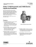
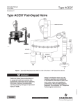
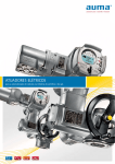
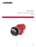
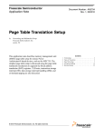
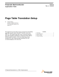
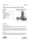
Instruction Manual 2100 and 2100E Liquid Level Switches D200119X012 February 2014 Fisherr 2100 Pneumatic and 2100E Electric Liquid Level Switches Contents Introduction . . . . . . . . . . . . . . . . . . . . . . . . . . . . . . . . . 1 Scope of Manual . . . . . . . . . . . . . . . . . . . . . . . . . . . . . 1 Description . . . . . . . . . . . . . . . . . . . . . . . . . . . . . . . . . 2 Specifications . . . . . . . . . . . . . . . . . . . . . . . . . . . . . . . 2 Educational Services . . . . . . . . . . . . . . . . . . . . . . . . . 4 Installation . . . . . . . . . . . . . . . . . . . . . . . . . . . . . . . . . . 4 Hazardous Area Classfication Information and Safe Use Instructions . . . . . . . . . . . . . . . . . . . 4 Installation Procedures . . . . . . . . . . . . . . . . . . . . . . . 6 Common Procedures for Either Switch . . . . . . . 6 Additional Procedures for 2100 Switch . . . . . . 6 Additional Procedures for 2100E Switch . . . . . 7 Calibration Check . . . . . . . . . . . . . . . . . . . . . . . . . . . . 8 Principle of Operation . . . . . . . . . . . . . . . . . . . . . . . . . 9 Maintenance . . . . . . . . . . . . . . . . . . . . . . . . . . . . . . . . 10 Operational Test . . . . . . . . . . . . . . . . . . . . . . . . . . . . 10 2100 Switch Maintenance Procedure . . . . . . . . . . 12 2100E Switch Maintenance Procedure . . . . . . . . . 13 Parts Ordering . . . . . . . . . . . . . . . . . . . . . . . . . . . . . . . 14 Parts Kits . . . . . . . . . . . . . . . . . . . . . . . . . . . . . . . . . . . 14 Parts List . . . . . . . . . . . . . . . . . . . . . . . . . . . . . . . . . . . 15 Figure 1. Fisher 2100 Pneumatic Liquid Level Switch APPROXIMATE SWITCHING POINT Introduction Scope of Manual This instruction manual includes installation, maintenance, and parts information for the 2100 pneumatic and 2100E electric liquid level switches. Refer to separate instruction manuals when you require information regarding related valves, actuators, positioners, and accessories. Do not install, operate or maintain a 2100 pneumatic or a 100E electric liquid level switch without being fully trained and qualified in valve, actuator and accessory installation, operation and maintenance. To avoid personal injury or property damage it is important to carefully read, understand, and follow all of the contents of this manual, including all safety cautions and warnings. If you have any questions about these instructions, contact your Emerson Process Management sales office before proceeding. www.Fisher.com 2100 and 2100E Liquid Level Switches Instruction Manual D200119X012 February 2014 Description The on‐off 2100 pneumatic switch (figure 1) and the 2100E electric switch (figure 2) operate shutdown valves or alarm systems when liquid in a vessel reaches a predetermined level. The 2100 switch uses an externally mounted displacer that operates a nozzle‐flapper to vent the supply pressure when the switch is activated. The nozzle‐flapper has a soft seat for tight shutoff when the switch is in its normal position (flapper against the nozzle). The 2100E switch uses the displacer torque to activate and deactivate an electric switch for positive on‐off service. The displacer on each type can withstand up to 1‐1/2 times the maximum working pressure, allowing it to remain in the cage during hydrostatic testing. Unless otherwise noted, all NACE references are to NACE MR0175-2002. Figure 2. Fisher 2100E Electric Liquid Level Switch APPROXIMATE SWITCHING POINT X0682 Specifications Specifications for the 2100 and 2100E switches are shown in table 1. WARNING This product is intended for a specific current range, temperature range and other application specifications. Applying different current, temperature and other service conditions could result in malfunction of the product, property damage or personal injury. 2 Instruction Manual 2100 and 2100E Liquid Level Switches D200119X012 February 2014 Table 1. Specifications Input Signal Displacer Diameter Liquid level 102 mm (4 inches) Minimum Process Liquid Specific Gravity 0.5 (consult your Emerson Process Management sales office for specific gravity below this value) Output Signal 2100 Switch: Output equal to supply pressure when the switch is in the normal position (flapper against nozzle). Output reduced to approximately atmospheric pressure, depending upon size of the bleed orifice and piping configuration, when the switch is activated 2100E Switch: Same as supply signal Supply Signal 2100 Switch: J 2.1 to 4.1 bar (30 to 60 psig), J 4.1 to 6.9 bar (60 to 100 psig), or J 6.9 to 10.3 bar (100 to 150 psig) 2100E Switch: 11 amperes, 1/4 horsepower at 125/250 volts AC; 5 amperes resistive, 3 amperes inductive at 28 volts DC Supply Medium (2100 Switch) Air or Natural Gas(1) Steady‐State Air Consumption(2) (2100 Switch) Less than 0.03 normal m3/hr (1.0 scfh) for all supply pressures when the liquid level is 25.4 mm (1 inch) below the normal switch position (flapper against nozzle) for high‐level switching or 25.4 mm (1 inch) above the normal switch position for low‐level switching Maximum Working Pressure(3) J153 bar (2220 psig) WOG(4) except J24 bar (350 psig) WOG is the maximum working pressure for sight window construction Operative Temperature Range(3) 2100 Switch: -29 to 204_C (-20 to 400_F) 2100E Switch: -29 to 82_C (-20 to 180_F) Process Connection Size 153 Bar (2220 psig) WOG(4): J1 NPT internal JDN 50 (NPS 2) Schedule 80 buttwelding ends, or JDN 50 (NPS 2) Schedule 160 buttwelding ends 2100 Switch Supply Pressure Connection Size 1/4 NPT internal 2100E Switch Electrical Connection Size 1/2 NPT external Hazardous Area Classification for 2100 Switch The 2100 pneumatic switch complies with the requirements of ATEX Group II Category 2 Gas and Dust Hazardous Area Classification for 2100E Switch CSA, FM, ATEX, IECEx, UL, Russian FSETAN, Russian GOST-R Refer to Hazardous Area Classifications and Special Instructions for “Safe Use” and Installations in Hazardous Location on page 4. Contact your Emerson Process Management sales office if additional information is required. Shipping Weight 17.2 kg (38 pounds) Declaration of SEP Fisher Controls International LLC declares this product to be in compliance with Article 3 paragraph 3 of the Pressure Equipment Directive (PED) 97 / 23 / EC. It was designed and manufactured in accordance with Sound Engineering Practice (SEP) and cannot bear the CE marking related to PED compliance. However, the product may bear the CE marking to indicate compliance with other applicable European Community Directives. NOTE: Specialized instrument terms are defined in ISA Standard 51.1 - Process Instrument Terminology. 1. Natural gas should contain no more than 20 ppm of H2S. 2. Normal m3/hr—normal cubic meters per hour (0_C and 1.01325 bar, absolute); scfh—standard cubic feet per hour (60_F and 14.7 psia) 3. Pressure and temperature limits in this document and any applicable standards or code limitations should not be exceeded. 4. Water, Oil, Gas maximum working pressure rating. Corresponds to Cold Working Pressure: the maximum pressure rating allowed under normal ambient temperature conditions, which are usually understood to be -29_C to 38_C (-20_F to 100_F). Refer to MSS SP‐25. 3 2100 and 2100E Liquid Level Switches Instruction Manual February 2014 D200119X012 Educational Services For information on available courses for 2100 pneumatic and 2100E electric liquid level switches, as well as a variety of other products, contact: Emerson Process Management Educational Services, Registration P.O. Box 190 Marshalltown, IA 50158-2823 Phone: 800-338-8158 or 641-754-3771 FAX: 641-754-3431 e‐mail: [email protected] Installation WARNING Always wear protective clothing, gloves, and eyewear when performing any installation operations to avoid personal injury. Check with your process or safety engineer for any additional measures that must be taken to protect against process media. If installing into an existing application, also refer to the WARNING at the beginning of the Maintenance section in this instruction manual. Hazardous Area Approvals and Special Instructions for “Safe Use” and Intallations in Hazardous Locations 2100E Electrical Switch Component Inspect the electrical switch component in your 2100E electric liquid level switch to determine the part number of the switch component, if specified. Contact your Emerson Process Management sales office if additional information is needed. CSA— Class I, Division 1, Groups A, B, C, and D; Class II, Division 1, Groups E, F, and G ; Dual Seal FM— XP Class I, Division 1, Groups A, B, C, D T6; DIP Class II, Division 1, Groups E, F, G T6; IP66 Special Conditions of Use: Model 057-0770 has temperature classification T5 for 11 Amp and T6 for 5 Amp Ambient temperature: 11 A, Ta = 75_C ; 5 A, Ta = 70_C Model 057-0771 has temperature classification T4 for 11 Amp and T6 for 5 Amp Ambient temperature: 11 A, Ta = 65_C ; 5 A, Ta = 70_C 4 Instruction Manual D200119X012 2100 and 2100E Liquid Level Switches February 2014 ATEX— II 2 G D IECEx— Ex d IIC T4/T5/T6 Gb ; Ex tb IIIC Txx_C Db Model 057-0770: Gas Ex d IIC T6 (Ta = -40_C to +70_C) (5 A Max) ; Ex d IIC T5 (Ta = -40_C to +75_C) (11 A Max) Dust Ex tb IIIC T85_C Db IP6X (Ta = -40_C to +70_C) (5 A Max) ; Ex tb IIIC T100_C Db IP6X (Ta = -40_C to +75_C) (11 A Max) Model 057-0771: Gas Ex d IIC T6 (Ta = -40_C to +70_C) (5 A Max) ; Ex d IIC T4 (Ta = -40_C to +65_C) (11 A Max) Dust Ex tb IIIC T85_C Db IP6X (Ta = -40_C to +70_C) (5 A Max) ; Ex tb IIIC T135_C Db IP6X (Ta = -40_C to +65_C) (11 A Max) Special Conditions for Safe Use: Each Electrical Snap-Switch Assembly shall be installed such that the equipment wiring is protected from mechanical damage. The equipment wiring must not be subjected to tension or torque. If it is to be terminated within a potentially explosive atmosphere, a suitably certified termination facility must be used. UL— Class I Division 1 Groups A,B,C,D ; Class II Division 1 Groups E,F,G 2100E Electric Switch Assembly Federal Service on Ecological, Technological, and Nuclear Supervision (Russian FSETAN)— Permit to Use: No PPC 00050247 ; Certificate of Conformity: No POCC US. GB06.B01314 Federal Agency on Technical Regulating and Metrology (Russian GOST-R)— Certificate number No. РОСС US.ГБ06.В01314 ; 1ExdIICT4/T5/T6; IP66 Ambient Temperature: T4 DPDT, 11 A maximum current, -40 to 65_C T5 SPDT, 11 A maximum current, -40 to 75_C T6 SPDT and DPDT, 5 A maximum current, -40 to 70_C Conditions of Application 1. Level switch should be applied in accordance to the assigned explosion proof mark, requirements of GOST R 51330.13, valid «Rules for electrical equipment installations» (PUE ch. 7.3), «Regulations for Operation of Consumer Electrical Installations» (PTEEP ch. 3.4), other normative documents regulating application of electrical equipment in explosion hazardous zones and manufacturer operation manual D200119X012. 2. Possible explosion hazard zones of application, categories and groups of explosion hazard mixtures of gases and vapors with air – in accordance to the requirements of GOST R 51330.9, GOST R 51330.11 and «Rules for electrical equipment installations» (PUE ch. 7.3). 3. Level switch should be operated with certified cable inputs and plugs that should provide necessary type and level of explosion protection and level of enclosure protection. 4. Alteration of level switch design concerning explosion proof means should be agreed with accredited test organization. 5 2100 and 2100E Liquid Level Switches Instruction Manual February 2014 D200119X012 Installation Procedures The installation procedures include those common to both the 2100 pneumatic and 2100E electric liquid level switches and additional ones for each switch. Common Procedures for Either Switch The horizontal line forged on the displacer cage indicates the approximate switching point (figures 1 and 2). When you mount the 2100 or 2100E switch, position it so that the horizontal line corresponds to the horizontal level at which switching is desired. Before you install the 2100 or 2100E switch, remove the plastic plugs from the process connections. One of these plugs retains a paper tube that protects the displacer and torque tube during handling and shipping. This paper tube must also be removed. There are two process connections; one at the top and one at the bottom of the cage. To mount the switch, connect the appropriate top and bottom process connections to the vessel using the required size pipe. The pipe must be capable of supporting the assembly and of withstanding the pressure involved. Use accepted piping and welding practices when making connections. Install isolating valves between the vessel and cage. Plugs are furnished for the unused process connections. However, one of the plugs can be removed, and a bleed valve or drain can be installed in one of the unused connections. Additional Procedures for 2100 Switch If using natural gas as the pneumatic supply medium, natural gas will be used in the pressure connections of the unit to any connected equipment. The unit will vent natural gas into the surrounding atmosphere, unless it is remote vented. WARNING Personal injury or property damage may occur from an uncontrolled process if the 2100 switch supply medium is not clean, dry air or noncorrosive gas. If clean, dry air, or noncorrosive gas is not used, the switch may become inoperative and allow the level in a process vessel to exceed safe limits. Install a 40 micrometer filter and suitable equipment to dry the supply medium and establish a maintenance cycle to check the filter and equipment. If the existing supply medium is corrosive, make sure the tubing and instrument components that contact the corrosive medium are suitable corrosion‐resistant materials, or use a noncorrosive medium. WARNING Personal injury or property damage may result from fire or explosion if natural gas is used as the supply medium and preventative measures are not taken. Preventative measures may include: Remote venting, re‐evaluating the hazardous area classification, ensuring adequate ventilation, and the removal of any ignition sources. Refer to figure 5 except as noted. 1. Connect a supply pressure line to the 1/4 NPT internal connection located in the back plate (key 10). 2. Install an output line between the supply pressure line and the equipment to be operated by the switch. 3. Install a street tee and bleed orifice (keys 34 and 35, figure 3) or other fixed restriction in the supply pressure line between the supply source and the output signal line. 6 Instruction Manual 2100 and 2100E Liquid Level Switches D200119X012 February 2014 Figure 3. Detail of Optional Street Tee and Bleed Orifice BACK PLATE (KEY 10) 1/4 NPT SUPPLY PRESSURE CONNECTION BLEED ORIFICE (KEY 35) STREET TEE (KEY 34) 1/4 NPT OUTPUT PRESSURE CONNECTION A3619‐1 4. If a remote vent is required, remove the vent assembly (key 23) from the 1/4 NPT internal vent connection and install a vent line to an area where the operating medium can be safely exhausted. Note The vent line should have as large a diameter as possible with a minimum number of bends and elbows. The vent line should be as short as possible. Protect the end of the vent pipe from the entrance of rain, snow, insects, or any other foreign material that may plug the vent line. Inspect the vent line opening periodically to ensure that it is not plugged. If necessary to change to a different supply pressure, install a different nozzle according to steps 1. through 4. and 15. through 18. of the 2100 switch maintenance procedure. To change switch action from low‐level to high‐level switching or vice versa, reverse the positions of the nozzle, flapper, and magnet according to steps 1. through 7. and 10. through 18. of the 2100 switch maintenance procedure. To change switch mounting from right‐hand to left‐hand or vice versa, perform steps 1. through 7. and 9. through 18. of the 2100 switch maintenance procedure. Additional Procedures for 2100E Switch Refer to figure 6. To install for standard action, connect electrical wires as shown in table 2. Table 2. Fisher 2100E Wiring Codes Wire Color Red Brown Blue Green Black Yellow Purple SPDT Normally Closed Common Normally Open Ground DPDT Switch 1 Normally Closed Common Normally Open Ground DPDT Switch 2 Ground Normally Closed Common Normally Open 7 2100 and 2100E Liquid Level Switches Instruction Manual February 2014 D200119X012 To change switch action from low‐level to high‐level switching, or vice versa, perform steps 1. through 4. and 13. through 17. of the 2100E maintenance procedure. To reverse action of the 2100E switch, refer to table 2 and reinstall wiring for normally open (NO) switches to normally closed (NC) and vice versa. To change switch mounting from right‐hand to left‐hand or vice versa, perform steps found in the 2100 switch maintenance procedure. Calibration Check For either type of switch, calibration can be checked by varying the level of the process liquid in the cage and observing the switch operation. If the process connection directly on top of the cage is not piped to the tank, close the isolating valves and fill the cage with process liquid through the top connection. Verify that the switch operates as the cage is being filled. Repeat the calibration procedure if necessary. Calibration can also be checked on the work bench. Connect a flexible hose from one of the bottom process connections to the bottom of a bucket. The top process connection should be open. Fill the bucket with process liquid. As the bucket is raised or lowered, the liquid level in the displacer cage rises or falls. Verify that the switch operates as the level is varied. Repeat the calibration procedure if necessary. Dry calibration can be performed on the 2100E using the following procedure: Refer to figure 6. 1. Position the cage and displacer assembly (key 1) so that the displacer is hanging downward. 2. Level the switch arm (key 40), if required. 3. Loosen the locknut (key 33) and adjust the machine screw (key 31) until it contacts the switch. 4. For low‐level dry calibration, tighten the locknut. For high‐level dry calibration, turn the machine screw one additional full turn, then tighten the locknut. 8 Instruction Manual 2100 and 2100E Liquid Level Switches D200119X012 February 2014 Principle of Operation The 2100 switch (figure 4) is an external, cage‐mounted, pneumatic liquid level switch. When the switch is in the normal position with the flapper against the nozzle, output pressure cannot bleed off and remains the same as full supply pressure. Rising liquid level exerts a buoyant force on the displacer, producing a torque in the torque tube. When this torque exceeds the torque exerted on the flapper by the magnet, the flapper snaps away from the nozzle. This action allows output pressure to bleed through the nozzle faster than supply pressure can enter through the bleed orifice. Figure 4. Principle of Operation for High‐Level Fisher 2100 Switch DISPLACER TORQUE TUBE SUPPLY OPTIONAL BLEED ORIFICE NOZZLE FLAPPER MAGNET SHUTDOWN VALVE (OR ALARM SYSTEM) OPTIONAL STREET TEE OUTPUT SIGNAL A3619‐2 The reduced pressure in the output signal line activates the shutdown or alarm system. When the liquid level lowers, the falling displacer forces the flapper into the field of the magnet, letting the magnet snap the flapper against the nozzle and causing output pressure to build to full supply pressure. On applications where low‐level switch operation is required, the nozzle, flapper, and magnet are positioned on the opposite side of the torque tube so that downward displacer travel moves the flapper away from the nozzle. The 2100E switch is an external, cage‐mounted, electric liquid level switch. Rising liquid level exerts a buoyant force on the torque tube that either activates or deactivates an electrical SPDT (single‐pole, double‐throw) or DPDT (double‐pole, double‐throw) switch depending on the required switching action. Falling liquid level deactivates or activates the same switch depending on the required action. 9 2100 and 2100E Liquid Level Switches Instruction Manual February 2014 D200119X012 Maintenance Switch parts are subject to normal wear and must be inspected and replaced when necessary. The frequency of inspection and replacement depends on the severity of service conditions. Refer to figure 5 for maintenance of the 2100 switch and figure 6 for maintenance of the 2100E switch. WARNING Always wear protective clothing, gloves, and eyewear when performing any maintenance procedures to avoid personal injury. The displacer is a sealed container inside the cage. A displacer penetrated by process fluid may retain pressure or hazardous fluid for an extended period. Such a displacer may contain pressure as a result of being in a pressurized vessel, or it may contain fluid that becomes pressurized due to changes in temperature and/or it may contain fluid that is hazardous or flammable. The sudden release of pressure, contact with hazardous fluid, fire, or explosion resulting in personal injury can occur if a displacer that is retaining pressure or process fluid is punctured or subjected to heat. Handle the cage (with displacer inside) with care in removing, storing, or disposing, taking into consideration the characteristics of the process fluid. To avoid personal injury and damage to the process system caused by the sudden release of pressure, contact with hazardous fluid, fire, or explosion, isolate and drain the displacer cage. For the 2100, shut off and bleed supply pressure from the switch before attempting any maintenance procedures. For the 2100E, shut off the power to the electric switch assembly before attempting any maintenance procedures. Check with your process or safety engineer for any additional measures that must be taken to protect against process media. The displacer cage should be flushed periodically to remove deposits or sludge that may affect proper operation. The frequency of flushing depends on the nature of the process liquid. Before flushing, close the isolating valves and drain the cage. Flush from one of the top connections to one of the bottom connections. Also, remove the pipe plug (key 2) or the bushing and sight window (keys 4 and 5), and flush from a top connection through the pipe plug or sight window connection. Inspect the vent or vent screen (key 23) or vent line periodically to ensure that the vent or vent line is not plugged. Table 3 lists various 2100 switch problems and possible solutions for them. The table is valid for either high‐level or low‐level switching action and for any supply pressure range. If a correction step requires replacement of worn or damaged parts, refer to the appropriate maintenance procedure in this manual for disassembly and reassembly instructions. 2100E switch problems are solved through common electrical troubleshooting procedures. Fault 4 of table 3 is also pertinent for the 2100E switch. Operational Test (2100 and 2100E) Establish a periodic operational test of the switch to ensure that: a. the torque tube is functioning as a continuous spring element; b. there is an absence of excessive friction; c. there is no contact with the mechanical stops, and; d. the torque tube is still effectively transmitting force and motion to the 2100 flapper and clamp assembly, or to the 2100E switch arm assembly. 10 Instruction Manual 2100 and 2100E Liquid Level Switches D200119X012 February 2014 Table 3. 2100 Troubleshooting Guide Fault 1. Nozzle‐flapper throttles (flapper moves in response to change in liquid level but does not completely cap or uncap nozzle). Possible Cause 1.1 Nozzle adjusted too high. Correction 1.1 If nozzle prevents flapper from coming in full contact with magnet, repeat the Calibration procedure. Perform the Calibration Check procedure to ensure that the unit operates properly. 1.2 Verify that the top surface of the magnet is parallel with the flapper and that the magnet is in full contact with the flapper when the flapper is against the magnet. If the above conditions do not exist, repeat the Calibration procedure. Perform the Calibration Check procedure to ensure that the unit operates properly. 2. Nozzle‐flapper fails to snap open. 2.1 Liquid level not changing in the expected direction. 2.1 Be certain liquid level in the displacer cage is changing in the expected direction. 3. Nozzle‐flapper leaks when shut off. 3.1 Surface of nozzle seat or nozzle worn or damaged. 3.1 Inspect surface of flapper seat (key 11, figure 5), and nozzle (key 6, figure 5); replace parts if necessary. 3.2 Nozzle adjusted too low. 3.2 Inspect nozzle‐flapper when flapper is being held by magnet. If nozzle is not seated on flapper seat, loosen locknut (key 33, figure 5) and rotate nozzle counterclockwise until it is seated. 3.3 Incorrect alignment of nozzle and flapper. 3.3 Inspect surface of nozzle seat (key 11, figure 5). This surface should be parallel with the opening in the end of the nozzle (key 6, figure 5). Correct as necessary. 4.1 Foreign material in cage. 4.1 Flush cage to remove foreign material. 4.2 Clamp and shaft assembly loose on torque tube assembly. 4.2 Perform step 4 of reassembly procedure in maintenance section. Tighten clamp nut on clamp and shaft assembly to between 20 and 27 NSm (15 and 20 lbSft). 4.3 Torque tube assembly failure. 4.3 Perform operational test procedure Replace torque tube assembly if it fails operational test. 4. Switch fails to activate upon high or low level depending on action selected. This test should be conducted with no process fluid in the cage using the following procedures: 1. Make sure the 2100 switch flapper and clamp assembly (key 12, figure 5) or the 2100E switch arm (key 40, figure 6) is tight on the shaft of the torque tube assembly (key 7). 2. Grasp and lift, then immediately release, the following: D The 2100 switch flapper and clamp assembly (key 12, figure 5), 10 to 13 mm (0.375 to 0.5 inch) from the nozzle (key 6, figure 5), or D The 2100E switch arm (key 40, figure 6), 10 to 13 mm (0.375 to 0.5 inch) from the contact of the electric switch assembly (key 49, figure 6). 3. The torque tube spring system is functional if the 2100 switch flapper and clamp assembly, or the 2100E switch arm, bounces at least two cycles in a reversing rotary motion. 11 2100 and 2100E Liquid Level Switches February 2014 Instruction Manual D200119X012 2100 Switch Maintenance Procedure WARNING When disconnecting any of the pneumatic connections, natural gas, if used as the supply medium, will seep from the unit and any connected equipment into the surrounding atmosphere. Personal injury or property damage may result from fire or explosion if preventative measures are not taken, such as adequate ventilation and the removal of any ignition sources. Refer to figure 5. 1. Drain the liquid from the cage and displacer assembly (key 1), then isolate it from the process. Shut off the supply pressure and bleed any trapped supply and output pressure from the nozzle block assembly (key 8). 2. Loosen the cover screws (key 17) and remove the cover (key 15). Replace the cover gasket (key 16) and the cover screw gaskets (key 20) if necessary. Note Magnetic attraction between the magnet (key 14) and the flapper (key 12) can be adversely affected by the presence of foreign material between the magnet and flapper. Before performing any inspection or correction step, inspect the magnet. If necessary, clean the magnet thoroughly. If cleaning requires removing the magnet or magnet bracket (key 13), perform step 17. of the maintenance procedure; then perform the calibration check procedure to ensure that the unit operates properly. 3. Loosen the nut holding the flapper and clamp assembly (key 12) to the shaft of the torque tube assembly (key 7). Remove the flapper and clamp assembly and, if necessary, replace the flapper seat (key 11) or magnet (key 14). The magnet is attached to the magnet bracket (key 13) with a machine screw (key 27). 4. Loosen the locknut (key 33), remove the nozzle (key 6), and if necessary, replace the nozzle O‐ring (key 26). If changing supply pressure is the only other maintenance performed, skip to step 15. . 5. Remove the pressure plug (key 9) and, if necessary, replace the pressure plug O‐ring (key 24). 6. Unscrew the pipe plug (key 2) or the bushing and sight window assembly (keys 4 and 5). With a 13 mm (1/2‐inch) hex nut driver, loosen the locknut on the displacer rod end of the cage and displacer assembly (key 1). 7. Remove the torque tube assembly (key 7) and the bearing (key 32) from the body block (key 3). If necessary, replace the torque tube O‐ring (key 25). 8. If it is necessary to replace the nozzle block assembly (key 8) or the nozzle block gasket (key 18), these parts are attached to the back plate (key 10) with cap screws (key 30) and lock washers (key 28). 9. If changing mounting position from right‐hand to left‐hand or vice versa, remove the cap screws (key 30) and lock washers (key 28) that hold the back plate (key 10) to the body block (key 3). Then rotate the body block 180 degrees on the cage and displacer assembly (key 1). Install a new body block gasket (key 19) if necessary, and secure the back plate (key 10) to the body block with lock washers and cap screws so that the greatest back plate overlap points are toward the bottom cage connection. 10. If changing from low‐level to high‐level switching or vice versa, remove the machine screws (key 31), flat washers (key 29), and magnet bracket (key 13). Install the magnet bracket on the opposite side of the nozzle block assembly (key 8) and secure it with flat washers and machine screws. 11. Replace the torque tube O‐ring (key 25) if necessary. Install the bearing (key 32) and torque tube assembly (key 7) into the body block (key 3), making sure the shaft of the torque tube assembly goes through the hole in the displacer rod end of the cage and displacer assembly (key 1). 12. With a tool inserted through the bottom process connection of the cage and displacer assembly (key 1), move the displacer to its upward travel limit and then tighten the locknut on the displacer rod end to between 20 and 27 NSm (15 and 20 lbfSft). 12 Instruction Manual 2100 and 2100E Liquid Level Switches D200119X012 February 2014 13. Install the pipe plug (key 2), or the bushing and sight window assembly (keys 4 and 5), into the body block (key 3). Torque the pipe plug, or the bushing and sight window assembly, to between 68 and 136 NSm (50 and 100 lbfSft). 14. Install the pressure plug (key 9) with the attached O‐ring (key 24) into the nozzle block assembly (key 8) on the opposite side from the magnet (key 14) and magnet bracket (key 13). 15. Install a nozzle (key 6) of the correct supply pressure range with attached O‐ring (key 26) and locknut (key 33) into the nozzle block assembly (key 8) on the same side as the magnet (key 14) and magnet bracket (key 13). 16. Install the flapper and clamp assembly (key 12) on the shaft of the torque tube assembly (key 7) with the flapper seat (key 11) centered over the nozzle (key 6), with the flapper at a 90‐degree angle to the center line of the nozzle, and with the end of the flapper flat and fully on the magnet (key 14). D For low‐level switching, tighten the nut of the flapper and clamp assembly (key 12) just enough to allow the flapper to rotate on the shaft of the torque tube assembly when light force is applied to the flapper. D For high‐level switching, tighten the nut of the flapper and clamp assembly (key 12) and the machine screws (key 31) to secure the magnet bracket and magnet (keys 13 and 14). 17. Adjust the nozzle (key 6) and flapper (key 12) as follows: D For low‐level switching, rotate the nozzle (key 6) counterclockwise (up) until it is in contact with the flapper seat (key 11). Rotate the nozzle an additional 1.5 turns in the counterclockwise direction, and fully tighten the flapper clamp. Rotate the nozzle 1.5 turns clockwise (down). Tighten the locknut (key 33). D For high‐level switching, rotate the nozzle (key 6) counterclockwise (up) until it is in contact with the flapper seat (key 11). Tighten the locknut (key 33). 18. Install the cover (key 15) with the attached cover gasket (key 16) and secure it with the cover screws (key 17) and attached cover screw gaskets. 2100E Switch Maintenance Procedure Refer to figure 6. 1. Drain the liquid from the cage and displacer assembly (key 1) and isolate it from the process. Shut off the power to the electric switch assembly (key 49). 2. Remove the cover screw (key 61) and open the cover (key 60) on the switch housing (key 55). Replace the cover gasket (key 57) if necessary. 3. Loosen the locknut (key 33) on the shaft clamp screw (key 41); then remove the switch arm (key 40) with the attached machine screw (key 31), and locknut (key 33). 4. If changing from high‐level to low‐level switching or vice versa, from right‐ to left‐hand mounting or vice versa, or a combination of both, loosen the set screws (key 56) and remove the electric switch assembly (key 49) and plug (key 54). 5. Unscrew the pipe plug (key 2) or the bushing and sight window assembly (keys 4 and 5). With a 13 mm (1/2‐inch) socket, loosen the locknut on the displacer rod end of the cage and displacer assembly. 6. Remove the torque tube assembly (key 7) and bearing (key 32) from the body block (key 3). 7. For changing from right‐ to left‐hand mounting or vice versa, remove the cap screws (key 30) that hold the switch housing (key 55) to the body block (key 3). 8. Rotate the body block (key 3) 180 degrees on the cage and displacer assembly (key 1). 9. Install a new body block gasket (key 42), if necessary. Secure the switch housing (key 55) to the body block (key 3), with the switch mounting ports pointing down, using cap screws (key 30). 10. Replace the torque tube O‐ring (key 25) if necessary. Install the bearing (key 32) and torque tube assembly (key 7) into the body block (key 3), making sure the shaft of the torque tube assembly goes through the hole in the displacer rod end of the cage and displacer assembly (key 1). 13 Instruction Manual 2100 and 2100E Liquid Level Switches D200119X012 February 2014 11. With a tool inserted through the bottom process connection of the cage and displacer assembly (key 1), move the displacer to its upward travel limit and then tighten the locknut on the displacer rod end to between 20 and 27 NSm (15 and 20 lbfSft). 12. Install the pipe plug (key 2), or the bushing and sight window assembly (keys 4 and 5), into the body block (key 3). Torque the pipe plug, or bushing and sight window, to between 68 and 136 NSm (50 and 100 lbfSft). 13. Select a switch mounting port that will provide the desired switching action. Screw the electric switch assembly into the selected port until the switch assembly groove aligns with the threaded hole for the set screw (key 56). Position the electric switch contact directly below the machine screw (key 31). Install and tighten the set screw (key 56) to anchor the electric switch assembly. 14. Insert the cap plug (key 54) in the unused switch mounting port. Install the set screw (key 56) in the mounting port of the switch housing (key 55). 15. Install the switch arm (key 40) on the shaft of the torque tube assembly (key 7) with the head of the shaft clamp screw (key 41) pointing toward the top process connection and the switch arm parallel to the top of the electric switch assembly (key 49). Tighten the locknut (key 33) on the shaft clamp screw to secure the switch arm. 16. Thread the machine screw (key 31) in or out of the switch arm (key 40) until it touches the contact of the electric switch assembly (key 49), then tighten the locknut (key 33). 17. Secure the cover (key 60) to the switch housing (key 55) with the cover screw (key 61). Parts Ordering When corresponding with your Emerson Process Management sales office about this equipment, always mention the unit's serial number. When ordering replacement parts, refer to the part number of each required part as found in the following parts list. WARNING Use only genuine Fisher replacement parts. Components that are not supplied by Emerson Process Management should not, under any circumstances be used in any Fisher instrument. The use of components not manufactured by Emerson Process Management may void your warranty, might adversely affect the performance of the instrument, and could result in personal injury and property damage. Parts Kits Key Description 2100 Repair Kit (included are keys 7, 11, 12, 14, 16, 18, 19, 20, 24, 25, 26, and 32) 14 Key Part Number R2100X00012 Description 2100E Retrofit Kit (included are the switch arm assy and keys 21, 28, 30, 38, 39, 42, 44, 45, 46, 49, 50, and 51) SPDT Switch DPDT Switch Part Number R2100EX0SP2 R2100EX0DP2 Instruction Manual 2100 and 2100E Liquid Level Switches D200119X012 February 2014 Parts List Note Part numbers are shown for recommended spares only. For part numbers not shown, contact your Emerson Process Management sales office. 2100 Switch (figure 5) Key Description 1 Cage & Displacer Assembly Part Number To comply with NACE MR0175‐2002, heat‐treated steel and stainless steel w/o sight window For 2220 WOG max working pressures w/1 NPT process connections w/NPS 2 Sch 80 BWE process connection2 w/NPS 2 Sch 160 BWE process connections 2 3 4 5 6 7* 8 Key Description 11* 12* Flapper Seat, fluorocarbon Flapper and Clamp Assembly, stainless steel 13 14* 15 16* 17 18* 19* 20* Magnet Bracket, stainless steel Magnet, sintered Alnico Cover, plastic Cover Gasket, chloroprene Cover Screw, stainless steel (2 req'd) Nozzle Block Gasket, silicone rubber Body Block Gasket, silicone rubber Cover Screw Gasket, silicone rubber (2 req'd) 21 Nameplate, aluminum Right or left‐hand mounting Vent Assembly, plastic O‐Ring, fluorocarbon O‐Ring, fluorocarbon O‐Ring, fluorocarbon Machine Screw, stainless steel Lock Washer, stainless steel (4 req'd) Flat Washer, stainless steel (2 req'd) 23 24* 25* 26* 27 28 29 30 31 32* 33 34 35* 36 37 47 For other than NACE applications, carbon steel w/sight window For 350 WOG max working pressure w/1 NPT process connection w/o sight window For 2220 WOG max working pressures w/1 NPT process connection w/NPS 2 Sch 80 BWE process conns w/NPS 2 Sch 160 BWE process conns Pipe Plug (2 req'd w/sight window; 3 req'd w/o sight window) 1 Pressure Plug, S30300 (303) stainless steel Back Plate, steel *Recommended spare parts 12A1578X012 15A2837X012 11A8641X012 11A8642X012 11A8643X012 1N463906382 1N571406382 1V826806382 11A8619X012 1D4835X0012 Cage & Displacer Assembly To comply with NACE MR0175‐2002, heat‐treated steel and stainless steel w/o sight window For 2220 WOG max working pressures w/1 NPT process connections w/NPS 2 Sch 80 BWE process connections w/NPS 2 Sch 160 BWE process connections For other than NACE applications, carbon steel w/sight window For 350 WOG max working pressure w/1 NPT process connection w/o sight window For 2220 WOG max working pressures w/1 NPT process connections w/NPS 2 Sch 80 BWE process connections w/NPS 2 Sch 160 BWE process connections 26A3197X022 2 9 10 11A8630X012 18A5221X012 2100E Switch (figure 6) Body Block To comply with NACE MR0175‐2002, NACE steel For other than NACE applications, steel Bushing (for use only w/sight window), steel Sight Window, glass and alloy steel Nozzle, S30300 (303) stainless steel 2.1 to 4.1 bar (30 to 60 psig) supply pressure 4.1 to 6.9 bar (60 to 100 psig) supply pressure 6.9 to 10.3 bar (100 to 150 psig) supply pressure Torque Tube Assembly, N04400 Nozzle Block Assembly, aluminum & stainless steel Cap Screw, stainless steel (4 req'd) Machine Screw, stainless steel (2 req'd) Bearing, glass‐filled PTFE Locknut, stainless steel Street Tee (figure 4), STC/PL steel Street Tee, STL/PL Bleed Orifice (figure 4), S31600 NACE Tag (not shown) 18‐8 stainless steel Tag Wire (not shown), 303 stainless steel Thread locking adhesive, medium strength (not furnished with switch) Part Number Pipe Plug (2 req'd w/sight window; 3 req'd w/o sight window) 15 Instruction Manual 2100 and 2100E Liquid Level Switches D200119X012 February 2014 Figure 5. Fisher 2100 Switch Assembly Drawing D D SECTION C‐C DETAIL OF RIGHT HAND MOUNTING WITH NOZZLE AND FLAPPER POSITIONED FOR LOW LEVEL SWITCHING (ALSO TYPICAL OF HIGH LEVEL SWITCHING WITH LEFT HAND MOUNTING) DETAIL OF SIGHT WINDOW CONSTRUCTION C VIEW B‐B C VIEW B‐B APPLY LUB/SEALANT/ADHESIVE 51A8650-H SECTION D‐D Key Description Key Description 3 Body Block, To comply with NACE MR0175‐2002, NACE steel For other than NACE applications, steel Bushing (for use only w/sight window), steel 5 7* Sight Window, glass and alloy steel Torque Tube Assembly, N04400 21 Nameplate, aluminum, Right or left‐hand mtg 4 16 *Recommended spare parts Part Number 26A3197X022 Instruction Manual 2100 and 2100E Liquid Level Switches D200119X012 February 2014 Figure 6. Fisher 2100E Switch Assembly Drawing B SECTION A‐A VIEW B OPTIONAL SIGHT WINDOW A A 40B6593‐G 17 Instruction Manual 2100 and 2100E Liquid Level Switches D200119X012 February 2014 Key Description 25* 30 31 O‐Ring, fluorocarbon Cap Screw, stainless steel (2 req'd) Machine Screw, stainless steel 1N571406382 32* 33 36 37 Bearing, glass‐filled PTFE Locknut, stainless steel (2 req'd) NACE Tag (not shown), 18‐8 stainless steel Tag Wire (not shown), 303 stainless steel 11A8619X012 40 41 42* 46 Switch Arm, stainless steel Shaft Clamp Screw, stainless steel Body Block Gasket, silicone Drive Screw, 18‐8 stainless steel (2 req'd) 18 Part Number 11A8642X012 Key Description 49* Electric Switch Assembly, stainless steel Single pole double throw (SPDT) Double pole double throw (DPDT) 54 55 56 Plug, anodized aluminum Switch Housing, aluminum Set Screw, 18‐8 stainless steel (2 req'd) 57 61 60 Cover Gasket, Silicone 30A Cover Screw, stainless steel Cover, aluminum 58 59 Roll pin O‐Ring, nitrile *Recommended spare parts Part Number 20B5075X012 20B5076X012 Instruction Manual D200119X012 2100 and 2100E Liquid Level Switches February 2014 19 2100 and 2100E Liquid Level Switches February 2014 Instruction Manual D200119X012 Neither Emerson, Emerson Process Management, nor any of their affiliated entities assumes responsibility for the selection, use or maintenance of any product. Responsibility for proper selection, use, and maintenance of any product remains solely with the purchaser and end user. Fisher is a mark owned by one of the companies in the Emerson Process Management business unit of Emerson Electric Co. Emerson Process Management, Emerson, and the Emerson logo are trademarks and service marks of Emerson Electric Co. All other marks are the property of their respective owners. The contents of this publication are presented for informational purposes only, and while every effort has been made to ensure their accuracy, they are not to be construed as warranties or guarantees, express or implied, regarding the products or services described herein or their use or applicability. All sales are governed by our terms and conditions, which are available upon request. We reserve the right to modify or improve the designs or specifications of such products at any time without notice. Emerson Process Management Marshalltown, Iowa 50158 USA Sorocaba, 18087 Brazil Chatham, Kent ME4 4QZ UK Dubai, United Arab Emirates Singapore 128461 Singapore www.Fisher.com 20 E 1974, 2014 Fisher Controls International LLC. All rights reserved.