1
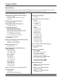
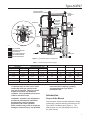
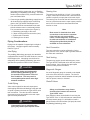
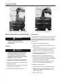
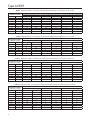
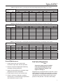
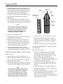
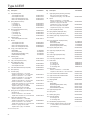
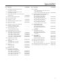
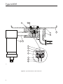
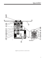
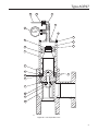
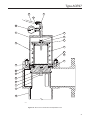
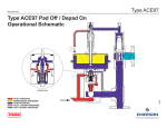
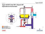
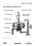
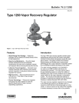
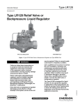
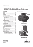
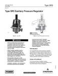
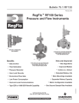
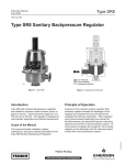
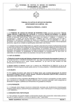
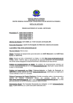
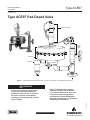
Type ACE97
Instruction Manual
Form 5665
November 2011
Type ACE97 Pad-Depad Valve
DEPAD PILOT VALVE
DEPAD
MAIN
VALVE
W8161
VENT
ACTUATOR
GAS INLET
PAD VALVE
TO TANK
Figure 1. Type ACE97 Pad-Depad Valve (NPS 1/2 / DN 15 Pad Valve / 1 NPT Depad Valve Shown)
!
WARNING
Fisher® pad-depad valves must be
installed, operated, and maintained
in accordance with federal, state, and
local codes, rules and regulations,
and Emerson Process Management
Regulator Technologies, Inc. (Regulator
Technologies) instructions.
D102773X012
Failure to follow these instructions or
to properly install and maintain this
equipment could result in an explosion,
fire and/or chemical contamination
causing property damage and personal
injury or death.
www.fisherregulators.com
Type ACE97
Specifications
Ratings and specifications for the Type ACE97 Pad-Depad valve are listed in the Specifications section below.
Factory specifications are stamped on the nameplate fastened to the actuator of the valve.
Pad (Tank Blanketing) Specifications
Pad Body Sizes and End Connection Styles
1/2, 1, and 2 NPT
NPS 1/2, 1, and 2 / DN 15, 25, and 50
CL150 RF
Maximum Operating Inlet Pressure(1)
200 psig / 13,8 bar
Maximum Main Valve Inlet Pressure(1)
200 psig / 13,8 bar
Inlet Operating Ranges(1)
NPS 1/2 / DN 15 pad valve:
25 to 200 psig / 1,7 to 13,8 bar
NPS 1 and 2 / DN 25 and 50 pad valves:
25 to 50 psig / 1,7 to 3,4 bar
51 to 120 psig / 3,5 to 8,2 bar
121 to 200 psig / 8,3 to 13,8 bar
Control Pressure Ranges(1)
See Table 1
Maximum and Minimum Differential Pressures(1)
25 psig / 1,7 bar minimum
200 psig / 13,8 bar maximum
Maximum Backpressure(1)
20 psig (1,4 bar)
Flow Coefficients for Relief Valve Sizing
(110% of rated Cv)
NPS 1/2 / DN 15:
Cv 0.2 use Cv 0.22
Cv 0.4 use Cv 0.44
NPS 1 / DN 25:
Cv 1 use Cv 1.1
Cv 2 use Cv 2.2
Cv 4 use Cv 4.4
Cv 7.5 use Cv 8.25
Cv 10 use Cv 11
NPS 2 / DN 50:
Cv 20 use Cv 22
Cv 45 use Cv 50
Cv 60 use Cv 66
Depad (Vapor Recovery) Specifications
Depad Body Sizes
1 and 2 NPT
NPS 3 and 4 / DN 80 and 100
Depad Pressure Ranges(1)
See Table 1
Valve Coefficients (110% of rated Cv)
1 NPT:
Cv 3 use Cv 3.3
Cv 6 use Cv 7
Cv 12 use Cv 13
Cv 17 use Cv 19
2 NPT:
Cv 20 use Cv 22
Cv 35 use Cv 39
Cv 70 use Cv 77
NPS 3 / DN 80:
Cv 90 use Cv 99
Cv 115 use Cv 127
Cv 140 use Cv 154
NPS 4 / DN 100:
Cv 150 use Cv 165
Cv 200 use Cv 220
Cv 280 use Cv 308
General Type ACE97 Specifications
Pressure Registration
External
Temperature Capabilities
Nitrile (NBR):
-20° to 180°F / -29° to 82°C
Fluorocarbon (FKM):
0° to 212°F / -18° to 100°C
Ethylenepropylene (EPDM - FDA):
-20° to 212°F / -29° to 100°C
Perfluoroelastomer (FFKM):
-20° to 212°F / -29° to 100°C
Approximate Weights
NPS 1/2 x 1 x 1 / DN 15 x 25 x 25:
70 pounds / 32 kg
NPS 1 x 2 x 2 / DN 25 x 50 x 50:
105 pounds / 48 kg
NPS 2 x 3 x 3 / DN 50 x 80 x 80:
175 pounds / 79 kg
1. The pressure/temperature limits in this Instruction Manual or any applicable standard limitation should not be exceeded.
2
Type ACE97
LOADING PRESSURE
EXHAUSTED BACK TO TANK
ON/OFF
DIAGNOSTIC
GAUGE
DEPAD PILOT
ADJUSTABLE
DEADBAND
REGULATOR
CONTROLLED
PRESSURE
RANGE SPRING
E
POPPET
CAGE
VENT
O-RING
SEAT
ACTUATOR
INLET
BLEED
INLET
RESSURE
PRESSURE
PHERIC PRESSURE
G PRESSURE
EDIATE PRESSURE
UPPLY PRESSURE
EDIATE BLEED PRESSURE
PANSION PRESSURE
M PRESSURE
RESSURE
S PRESSURE
E0005
RESSURE
RESSURE
PRESSURE
ST
OADING PRESSURE
EADER PRESSURE
LEED PRESSURE
DEPAD
MAIN
VALVE
ROLLING
DIAPHRAGM
SENSING
CONNECTION
DIAGNOSTIC
PORT
MAIN
VALVE
SPRING
OPEN PILOT
INLET PRESSURE
ATMOSPHERIC PRESSURE
TANK PRESSURE
PILOT LOADING PRESSURE
INERT GAS IN
TANK
CONNECTION
PAD VALVE
VENT HEADER PRESSURE
INLET BLEED PRESSURE
Figure 2. Type ACE97 Pad On / Depad Off
Table 1. Actuator Spring Pressure Ranges
CONTROL PRESSURE RANGES
Pad Setpoint
inches w.c.
SPRING FREE LENGTH
Depad Setpoint (Above Pad)
INCHES
mm
INCHES
mm
10 to 25
3.08
78,2
0.105
2,67
10 to 15
4.0
102
0.092
2,34
4 to 16
10 to 40
3.73
94,7
0.156
3,96
16 to 78
40 to 194
3.73
2.90
94,7
73,7
0.156
0.250
3,96
6,35
mbar
inches w.c.
mbar
0.5 to 3-
1 to 7
4 to 10
0.5 to 7
1 to 17
4 to 6
3 to 13
7 to 32
4 to 10
10 to 25
(1)
SPRING WIRE DIAMETER
(1)
0.5 to 1.4 psig
34 to 97 mbar
0.25 to 1 psig
17 to 69
3.8
96,5
0.250
6,35
1.0 to 2.2 psig
69 to 152 mbar
0.25 to 2 psig
17 to 138
3.8
96,5
0.313
7,95
1. Two nested springs are used (See Figure 12).
If a leak develops or if the unit or outlet
continually vents gas, service to the
unit may be required. Failure to correct
trouble could result in a hazardous
condition. Only a qualified person must
install or service the unit.
Installation, operation, and maintenance
procedures performed by unqualified
personnel may result in improper
adjustment and unsafe operation.
Either condition may result in equipment
damage or personal injury. Use qualified
personnel when installing, operating,
and maintaining the Type ACE97
pad-depad valve.
Introduction
Scope of the Manual
This instruction manual provides installation, startup,
maintenance, and parts ordering information for the
Type ACE97 Pad-Depad valve (Figure 1). The
product photo may vary depending on the size of
the valve ordered.
3
Type ACE97
LOADING PRESSURE
EXHAUSTED BACK TO TANK
URE
SSURE
C PRESSURE
SSURE
E PRESSURE
Y PRESSURE
E BLEED PRESSURE
ON PRESSURE
SSURE
URE
SSURE
URE
URE
SURE
DEPAD PILOT
CONTROLLED
PRESSURE
RANGE SPRING
REGULATOR
NG PRESSURE
R PRESSURE
PRESSURE
RE
ON/OFF
DIAGNOSTIC
GAUGE
DEPAD
MAIN
VALVE
Vent
POPPET
VENT
ACTUATOR
CAGE
O-RING
SEAT
INLET
ROLLING
DIAPHRAGM
SENSING
CONNECTION
CLOSED PILOT
DIAGNOSTIC
PORT
MAIN
VALVE
SPRING
E0004
INLET PRESSURE
ATMOSPHERIC PRESSURE
TANK PRESSURE
INERT GAS IN
PAD VALVE
TANK
CONNECTION
PILOT LOADING PRESSURE
VENT HEADER PRESSURE
Figure 3. Type ACE97 Pad Off / Depad On
Product Description
Principle of Operation
The Type ACE97 Pad-Depad valve is a self-contained,
pilot-operated valve that maintains a blanket of inert gas
on top of a stored product to protect it from atmospheric
contamination. It reduces combustibility, decreases
vaporization, controls vapor space pressure during
pump-in and pump-out operations, and prevents the
tank from entering a vacuum condition and collapsing
upon itself. The Type ACE97 valve provides excellent
and accurate pressure control of the vapor space in the
tank. Blanketing pressure is kept to a minimum in order
to conserve the use of blanketing gas.
Type ACE97 pilot-operated valves (except for the
NPS 1/2 / DN 15 pad valve) control the vapor space
pressure over a stored liquid. The unit is stainless
steel and is controlled by a very large actuator
diaphragm. The oversized actuator diaphragm
offers high sensitivity to changes in tank pressure.
When a storage tank cools and tank vapors condense,
Type ACE97 pad (tank blanketing) valves replace the
condensing vapors with an inert gas to prevent internal
tank pressure from decreasing. Positive tank pressure
prevents outside air from contaminating the product
and reduces the possibility of atmospheric pressure
collapsing the tank.
Pad (tank blanketing) is used to describe the process
of replacing the vapor space of a storage tank with
an inert gas.
Depad (vapor recovery) is used to describe the
process of relieving or venting the vapor space as
a result of pressure rise.
Tank and vapor recovery connections are available
to meet most customer requirements. A Single Array
Manifold (S.A.M) provides a single tank and sensing
connection and is required for tanks having a single
nozzle. Accessories include gauges, purge meters,
pressure switches, and check valves.
4
Additionally, Type ACE97 valves provide depad (vapor
recovery) capabilities through the depad main valve
and depad pilot valve. When the temperature outside
the tank rises causing the vapor inside the tank to
expand, Type ACE97 depad valve vents the excess
tank pressure to a safe place.
Type ACE97
PRESSURE
ET PRESSURE
SPHERIC PRESSURE
NG PRESSURE
MEDIATE PRESSURE
SUPPLY PRESSURE
MEDIATE BLEED PRESSURE
XPANSION PRESSURE
UM PRESSURE
PRESSURE
SS PRESSURE
PRESSURE
PRESSURE
T PRESSURE
UST
LOADING PRESSURE
HEADER PRESSURE
BLEED PRESSURE
LOADING PRESSURE
EXHAUSTED BACK TO TANK
DEPAD PILOT
ADJUSTABLE
DEADBAND
POPPET
CAGE
INLET
DEPAD
MAIN
VALVE
VENT
O-RING
SEAT
ACTUATOR
ROLLING
DIAPHRAGM
SENSING
CONNECTION
SSURE
SSURE
E
SSURE
SSURE
ED PRESSURE
ESSURE
E
CONTROLLED
PRESSURE
RANGE SPRING
REGULATOR
ON/OFF
DIAGNOSTIC
GAUGE
CLOSED PILOT
DIAGNOSTIC
PORT
MAIN
VALVE
SPRING
E0006
INLET PRESSURE
ATMOSPHERIC PRESSURE
TANK PRESSURE
INERT GAS IN
PAD VALVE
TANK
CONNECTION
PILOT LOADING PRESSURE
VENT HEADER PRESSURE
Figure 4. Type ACE97 Pad Off / Depad Off
NPS 1 and 2 / DN 25 and 50 Pad Valves
(Figure 2)
When tank pressure decreases below the pad setpoint
(due to pump-out operations or thermal cooling), the
actuator diaphragm moves downward pushing open
the pad pilot. This creates flow from the pad loading
chamber to downstream. When pad loading pressure
decreases, the force created by inlet pressure on
the pad main valve plug overcomes the main spring
force and opens the main valve plug allowing flow
through the pad valve to the tank. Once tank pressure
reaches pad setpoint, the pad pilot closes, pad loading
pressure equalizes with inlet pressure and the pad
valve closes.
NPS 1/2 / DN 15 Pad Valve (Not Shown)
The NPS 1/2 / DN 15 pad valve has a main valve only.
When tank pressure decreases below the pad setpoint
the actuator diaphragm moves downward pushing the
valve plug open and allowing flow through the pad
valve to the tank.
Depad (Figure 3)
When tank pressure increases above the depad
setpoint (due to pump-in operations or thermal
heating), the actuator diaphragm moves upward and
pushes open the depad pilot. This releases depad
loading pressure (nitrogen or other supply gas). When
depad pilot loading pressure decreases, the depad
main valve opens by a spring and allows flow from the
tank to the vent or recovery system.
The blanketing (padding) gas is used as the pilot fluid.
The link between the actuator and the depad main
valve is provided by the depad pilot valve, which is
located on top of the actuator. The depad pilot valve
is connected to the actuator by an adjustable coupling,
which can be rotated to adjust the depad setpoint. A
locknut is provided on the depad pilot valve to secure
the setpoint adjustment.
5
Type ACE97
DEPAD DIAGNOSTIC
GAUGE
TANK VAPOR SPACE
PRESSURE GAUGE
VENT CONNECTION
PAD DIAGNOSTIC
GAUGE
SENSING
CONNECTION
INLET PRESSURE GAUGE
INLET VALVE
SENSING LINE
BLANKETING GAS
SUPPLY LINE
LINE STRAINER
VALVE TANK
CONNECTION
BLANKETING GAS
CONNECTION
SHUTOFF VALVE
TANK VALVE
EMERGENCY
TANK VENT
NORMAL
TANK VENT
VAPOR SPACE
LIQUID
E0629
Figure 5. Type ACE97 Pad-Depad Valve Installation
Installation and Startup
!
WARNING
Personal injury, equipment damage, or
leakage due to escaping accumulated
gas or bursting of pressure-containing
parts may result if this gas blanketing
system is overpressured or installed
where service conditions could exceed
the limits given in the Specifications
section or on the valve nameplate, or
where conditions exceed any ratings of
the adjacent piping, piping connections,
or compatibility of valve materials with
process fluids.
To avoid such injury or damage, provide
pressure-relieving or pressure-limiting
devices (as required by Title 49, Part 192,
of the U.S. Code of Federal Regulations,
by the National Fuel Gas Code Title 54 of
the National Fire Codes of the National
Fire Protection Agency, or by other
applicable codes) to prevent service
conditions from exceeding those limits.
6
Additionally, physical damage to the
tank blanketing system could result in
personal injury and property damage
due to escaping gas or tank contents.
To avoid such injury and damage,
install the tank blanketing valve in
a safe location.
The Type ACE97 Pad-Depad valve is assembled and
preset to the customer specified pressure and setpoint.
The pressure ranges of the valve are stamped on the
nameplate attached to the upper actuator case.
1. Use qualified personnel when installing, operating,
and maintaining valves. Before installing, inspect
the main valve, pilot, and tubing for any shipment
damage or foreign material that may have
collected. Ensure that the body interior is clean
and the pipelines are free of foreign material.
Apply pipe compound only to the external pipe
threads with a threaded body, or use suitable
line gaskets and good bolting practices with
a flanged body.
2. Inspect the nameplate on the upper actuator
case. It displays the model number, serial number,
blanketing gas supply pressure range, maximum
inlet pressure, Cv value, and set pressures. These
Type ACE97
must agree with the system that you are Padding
(blanketing) or Depadding (recovering). The serial
number will be needed in any communication with
your local Sales Office.
3. Clean the gas padding (blanketing) supply lines of
all dirt and foreign material before connecting
them to the Type ACE97 Pad-Depad valve.
4. The valve should be mounted above the tank
with the actuator case in a horizontal position.
Four connections are required (see Figure 5):
a. Blanketing gas supply to the valve
b. Vapor recovery/process connection (vent)
c. System tank connection
d. Sensing line to the tank
Piping Considerations
Piping must be capable of supporting the weight of
the system. Use pipe supports when necessary.
Refer to Figure 5.
Inlet Piping
The padding (blanketing) gas supply line should be
equipped with a Number 100 mesh strainer to remove
dirt and pipe scale. Inlet piping must be sized to
adequately deliver padding (blanketing) gas at the
specified inlet pressure under full flow conditions.
CAUTION
Undersized piping may inadequately
deliver Padding (blanketing) gas at
the specified inlet pressure under full
flow conditions. This may result in
unacceptable performance under high
demand conditions.
Outlet Piping
Valve outlet is piped into the tank vapor space.
Outlet piping should be self-draining to the tank and
of equal or greater size than the Type ACE97 valve
tank connection. The valve should be situated
above and as close as possible to the tank vapor
space for best performance.
CAUTION
Unnecessarily long or restricted outlet
piping may result in poor setpoint control.
Sensing Line
The sensing line should be 1/2-inch / 13 mm tubing
or pipe, must slope toward the tank, and should not
contain low points (or traps) that could catch liquid.
The sensing line must enter the tank above the liquid
level at a point that senses the vapor space pressure
and is free from turbulence associated with tank
nozzles or vents.
Note
Best control is obtained when both
connections to the tank are separate.
If the tank has only one available
nozzle, contact Regulator Technologies
for alternate methods of installation.
A Single Array Manifold (S.A.M.) is
available for such situations.
Vent Connection
The vent connection must be self-draining, facing
away from the valve, and of equal or greater size than
the valve tank connection.
Tank Venting
The tank may require normal and emergency vents.
The Type ACE97 Pad-Depad valve does not perform
these functions, it only controls the vapor space
pressure under process conditions.
Diagnostic Gauges
An on/off diagnostic gauge is mounted on the depad
main valve at the inlet to the cylinder. The face on
the gauge is marked to indicate whether the main pad
valve is opened, closed, or throttled.
Shutoff Valves
Note
Safety considerations may dictate
shutoff valves between the tank and
Type ACE97 valve.
Inlet (isolation) valves are desirable for servicing the
Type ACE97 valve. If this valve was not ordered with
an inlet pressure gauge, it is advisable to install a
gauge between the inlet isolation (full-port) valve and
the padding (blanketing) valve.
7
Type ACE97
ADJUSTING SCREW
TUBING
LOCKNUT
COUPLING
ACTUATOR
E0679
E0678
Figure 6. Unthreading the Adjusting Coupling
Startup, Adjustment, and Shutdown
CAUTION
If required, tank vents (normal
and emergency) must be in place
and operating.
Figure 7. Changing the Pad Setpoint
Adjustment
The setpoint of this unit is factory set. If an adjustment
is to be made, it should be made in small increments
while the unit is controlling tank pressure. It is difficult
to make field adjustments due to the slow changes in
tank pressure.
To change the pad (blanketing) setpoint:
1. Disconnect the tubing from the depad pilot valve
(See Figure 6).
Startup
CAUTION
Always open the tank shutoff valve prior
to the inlet shutoff valve. Failure to do
so could result in inlet pressure being
applied to the actuator casing, potentially
damaging it. Refer to Figure 5.
1. Open the tank and sensing line shutoff valves
(between the Type ACE97 valve and tank).
2. A tank vapor space pressure gauge should be
installed and visible.
3. Slowly open the inlet shutoff valve (to the pad
valve) and leave it fully open.
4. Monitor the tank vapor space pressure.
2. Loosen the locknut (See Figure 7), but maintain its
position in relation to the adjusting coupling.
Doing so leaves the depad setpoint unchanged.
3. Separate the depad pilot valve from the actuator
by unthreading and removing.
4. Unthread and remove the adjusting coupling.
5. Increase the pad setpoint by turning the adjusting
screw clockwise. (Turning the screw counterclockwise
decreases the setpoint). See Figure 7.
6. Replace the depad adjusting collar against the
locknut to re-establish the depad setpoint.
To change the depad setpoint:
1. Loosen the locknut below the adjusting coupling.
2. Rotate the collar to change the setpoint. (The
bottom of the coupling—nearest the locknut—is
left-hand threaded).
3. Tighten the locknut.
8
Type ACE97
All O-rings, gaskets, and seals should be lubricated
with a good grade of general purpose lubricant and
installed gently rather than forced into position.
Approved lubricants, sealants, thread protectors,
and adhesives are as follows:
Table 2. Diagnostic Analysis Pressure Ranges
DIAGNOSTIC
STATUS
Equal to inlet supply pressure
Pilot and main valves are closed.
Tank pressure is at or above set pressure.
Slightly below inlet supply pressure
Pilot valve supplies gas to tank. Tank
pressure is just below set pressure.
Well below inlet supply pressure
Pilot and main valves are both
supplying gas to the tank. Tank
pressure is below setpoint.
Lubricants: Dow Corning® #111, Dow
Corning® #3452 Chemical Resistant Lubricant
Thread Protector: Anti-Seize
Sealant: Loctite® PST #592,
Polytetrafluoroethylene (PTFE) Tape
In any installation it is important to open and close
valves slowly and to close the inlet shutoff valve first
when shutting down the system.
Adhesive: Loctite® #222
Maintenance
Monthly Maintenance
Valve parts are subject to normal wear and must be
inspected and replaced as necessary. The frequency
of inspection and replacement of parts depend on the
severity of service conditions and the requirements
of local, state, and federal regulations. Due to the
care Regulator Technologies takes in meeting all
manufacturing requirements, use only replacement parts
manufactured or furnished by Regulator Technologies.
1. Visually inspect the unit to ensure tight
connections, tight seals, and safe operation.
Shutdown
Be certain that nameplates are updated to accurately
indicate any field changes in equipment, materials,
service conditions, or pressure settings.
2. Observe the pad and depad (tank blanketing
and vapor recovery) pressures.
3. Inspect the inlet pressure for the proper range
(stamped on the valve nameplate).
Table 3. Diagnostics Table: Cv 1 through 4, Inlet Pressure Range Spring 25 to 50 psig / 1,7 to 3,4 bar
ACTUAL INLET SUPPLY
PRESSURE TO VALVE
psig
DIAGNOSTIC PORT PRESSURE
Pressure when Pilot Starts to Open
bar
psig
bar
25
1,7
24
1,7
30
2,1
29
2,0
35
2,4
34
2,3
40
2,8
39
45
3,1
44
50
3,4
49
Pressure when Main Valve Starts to Open Pressure when Main Valve is Fully Open
psig
bar
psig
bar
9
0,62
2
0,14
13
0,90
6
0,41
16
1,1
9
0,62
2,7
20
1,4
13
0,90
3,0
24
1,7
17
1,2
3,4
28
1,9
21
1,4
Table 4. Diagnostics Table: Cv 1 through 4, Inlet Pressure Range Spring 51 to 120 psig / 3,5 to 8,3 bar
ACTUAL INLET SUPPLY
PRESSURE TO VALVE
DIAGNOSTIC PORT PRESSURE
Pressure when Pilot Starts to Open
Pressure when Main Valve Starts to Open
Pressure when Main Valve is Fully Open
psig
bar
psig
bar
psig
bar
psig
bar
51
3,5
50
3,4
29
2,0
5
0,35
60
4,1
59
4,1
36
2,5
12
0,83
70
4,8
69
4,8
43
3,0
19
1,3
80
5,5
79
5,4
51
3,5
27
1,9
90
6,2
89
6,1
59
4,1
34
2,3
100
6,9
99
6,8
66
4,5
42
2,9
110
7,6
109
7,5
74
5,1
50
3,4
120
8,3
119
8,2
81
5,6
57
3,9
9
Type ACE97
Table 5. Diagnostics Table: Cv 1 through 4, Inlet Pressure Range Spring 121 to 200 psig / 8,3 to 13,8 bar
ACTUAL INLET SUPPLY
PRESSURE TO VALVE
DIAGNOSTIC PORT PRESSURE
Pressure when Pilot Starts to Open Pressure when Main Valve Starts to Open Pressure when Main Valve is Fully Open
psig
bar
psig
bar
psig
bar
psig
bar
121
8,3
120
8,3
74
5,1
30
2,1
130
9,0
129
8,9
81
5,6
37
2,5
140
9,6
139
9,6
88
6,1
45
3,1
150
10,3
149
10,3
96
6,6
53
3,6
160
11,0
159
10,9
104
7,2
60
4,1
170
11,7
169
11,7
111
7,6
68
4,7
180
12,4
179
12,3
119
8,2
75
5,2
190
13,1
189
13,0
127
8,8
83
5,7
200
13,8
199
13,7
134
9,2
91
6,3
Table 6. Diagnostics Table: Cv 7.5 through 10, Inlet Pressure Range Spring 25 to 50 psig / 1,7 to 3,4 bar
ACTUAL INLET SUPPLY
PRESSURE TO VALVE
DIAGNOSTIC PORT PRESSURE
Pressure when Pilot Starts to Open
Pressure when Main Valve Starts to Open
Pressure when Main Valve is Fully Open
psig
bar
psig
bar
psig
bar
psig
bar
25
1,7
24
1,7
11
0,76
0
0,00
30
2,1
29
2,0
14
0,96
3
0,21
35
2,4
34
2,3
17
1,2
6
0,41
40
2,8
39
2,7
21
1,4
9
0,62
45
3,1
44
3,0
24
1,7
13
0,89
50
3,4
49
3,4
27
1,9
16
1,1
Table 7. Diagnostics Table: Cv 7.5 through 10, Inlet Pressure Range Spring 51 to 120 psig / 3,5 to 8,3 bar
ACTUAL INLET SUPPLY
PRESSURE TO VALVE
DIAGNOSTIC PORT PRESSURE
Pressure when Pilot Starts to Open
Pressure when Main Valve Starts to Open
Pressure when Main Valve is Fully Open
psig
bar
psig
bar
psig
bar
psig
bar
51
3,5
50
3,4
24
1,7
3
0,21
60
4,1
59
4,1
30
2,1
9
0,62
70
4,8
69
4,8
36
2,5
15
1,0
80
5,5
79
5,4
42
2,9
22
1,5
90
6,2
89
6,1
49
3,4
28
1,9
100
6,9
99
6,8
55
3,8
34
2,3
110
7,6
109
7,5
61
4,2
41
2,8
120
8,3
119
8,2
68
4,7
47
3,2
Table 8. Diagnostics Table: Cv 7.5 through 10, Inlet Pressure Range Spring 121 to 200 psig / 8,3 to 13,8 bar
ACTUAL INLET SUPPLY
PRESSURE TO VALVE
10
DIAGNOSTIC PORT PRESSURE
Pressure when Pilot Starts to Open
Pressure when Main Valve Starts to Open
Pressure when Main Valve is Fully Open
psig
bar
psig
bar
psig
bar
psig
bar
121
8,3
120
8,3
63
4,3
31
2,1
130
9,0
129
9,0
69
4,8
37
2,5
140
9,6
139
9,6
75
5,2
43
3,0
150
10,3
149
10,3
82
5,6
49
3,4
160
11,0
159
10,9
88
6,1
56
3,9
170
11,7
169
11,7
94
6,9
62
4,3
180
12,4
179
12,3
101
7,0
68
4,7
190
13,1
189
13,0
107
7,4
75
5,2
200
13,8
199
13,7
113
7,8
81
5,6
Type ACE97
Table 9. Diagnostics Table: Cv 20 through 60, Inlet Pressure Range Spring 25 to 50 psig / 1,7 to 3,4 bar
ACTUAL INLET SUPPLY
PRESSURE TO VALVE
DIAGNOSTIC PORT PRESSURE
Pressure when Pilot Starts to Open Pressure when Main Valve Starts to Open Pressure when Main Valve is Fully Open
psig
bar
psig
bar
psig
bar
psig
bar
25
1,7
24
1,7
16
1,1
5
0,21
30
2,1
29
2,0
20
1,4
9
0,62
35
2,4
34
2,3
24
1,6
14
0,96
40
2,8
39
2,7
29
2,0
18
1,2
45
3,1
44
3,0
33
2,2
23
1,6
50
3,4
49
3,4
38
2,6
27
1,9
Table 10. Diagnostics Table: Cv 20 through 60, Inlet Pressure Range Spring 51 to 120 psig / 3,5 to 8,3 bar
ACTUAL INLET SUPPLY
PRESSURE TO VALVE
DIAGNOSTIC PORT PRESSURE
Pressure when Pilot Starts to Open Pressure when Main Valve Starts to Open Pressure when Main Valve is Fully Open
psig
bar
psig
bar
psig
bar
psig
bar
51
3,5
50
3,4
39
2,7
11
0,76
60
4,1
59
4,1
48
3,3
19
1,3
70
4,8
69
4,8
57
3,9
28
1,9
80
5,5
79
5,4
66
4,5
37
2,5
90
6,2
89
6,1
75
5,2
46
3,2
100
6,9
99
6,8
84
5,8
55
3,8
110
7,6
109
7,5
93
6,4
64
4,4
120
8,3
119
8,2
102
7,0
73
5,0
Table 11. Diagnostics Table: Cv 20 through 60, Inlet Pressure Range Spring 121 to 200 psig / 8,3 to 13,8 bar
ACTUAL INLET SUPPLY
PRESSURE TO VALVE
DIAGNOSTIC PORT PRESSURE
Pressure when Pilot Starts to Open Pressure when Main Valve Starts to Open Pressure when Main Valve is Fully Open
psig
bar
psig
bar
psig
bar
psig
bar
121
8,3
120
8,3
103
7,1
60
4,1
130
9,0
129
8,9
111
7,6
68
4,7
140
9,6
139
9,6
120
8,3
77
5,3
150
10,3
149
10,3
129
8,9
86
5,9
160
11,0
159
10,9
138
9,5
95
6,5
170
11,7
169
11,7
147
10,1
104
7,2
180
12,4
179
12,3
156
10,8
113
7,8
190
13,1
189
13,0
165
11,4
122
8,4
200
13,8
199
13,7
174
12,0
134
9,2
Annual Maintenance
1. Visually inspect the unit to ensure tight
connections, tight seals, and safe operation.
2. Observe the pad and depad (tank blanketing
and vapor recovery) pressures.
3. Inspect the inlet pressure for the proper range
(stamped on the valve nameplate).
4. Visually inspect valve for any external wear.
5. If there is evidence of leakage or unstable
internal motion, a rebuild with seal replacement
and relubrication may be in order.
Pad Valve Diagnostics
Note
A pressure gauge must be installed
in the pad valve diagnostic port to
perform diagnostic analysis. See
Figures 2 through 4.
Diagnostics are an optional feature of the NPS 1 and 2
/ DN 25 and 50 Type ACE97 valves and aid in evaluating
valve operation. The diagnostic analysis relies on the
relationship of pad valve pilot pressure and the inlet
pressure of the pad valve. The basic relationships
11
Type ACE97
are shown in Table 2. In order to evaluate a valve,
examine the valve nameplate to determine the Cv and
inlet pressure range (main valve spring).
There are four pressures involved in evaluating a
valve: actual inlet pressure, pressure to start opening
pilot valve, pressure to start opening main valve, and
pressure to fully open main valve.
Actual Inlet Pressure: The gas pressure supplied
to the inlet of the valve. This is the maximum
diagnostic pressure.
Pressure to Start Opening Pilot Valve: The
diagnostic pressure drops to this value as the valve
senses decreasing tank pressure. The main pad
valve remains closed at this pressure.
Pressure to Start Opening Main Valve: The
diagnostic pressure drops to this level as the tank
pressure decreases the valve setpoint. The pilot is
fully open at this pressure.
Pressure to Fully Open Main Valve: At this point,
both the main valve and pilot valve are fully open
and supplying gas to the tank.
Follow these steps and refer to the diagnostics tables
(Tables 3 through 11) to evaluate a valve under actual
operating conditions:
1. Select the table (Tables 3 through 11) that
corresponds to the Cv and inlet pressure range
of your pad valve.
2. Determine the actual valve operating inlet pressure
in the first column of the diagnostics table.
3. In the second column of the table, determine the
pressure of the pilot as it opens.
4. Determine the diagnostic pressure for the start to
open pressure of the main valve in the third column.
operating and safety procedures.
If installed, electrical connections
to the explosion proof switch must
be deactivated before opening the
enclosure or disconnecting the
wiring (in accordance with codes
and safety practices).
Refer to the following instructions and to Figures 11
through 20 in the Parts Ordering section when
performing assembly and disassembly operations.
It is recommended that all seals and diaphragms be
replaced whenever a valve is disassembled and
re-assembled. Parts kits are available through your
local Sales Office.
Note
Have your model number, serial number,
inlet pressure, and set pressure range
available when ordering parts. Valve
information is on the nameplate (on the
upper actuator case).
The Type ACE97 Pad-Depad valve should be viewed
as four connected elements. These include the pad
valve, the actuator, the depad pilot valve, and the
depad main valve. See Figure 1.
Disassembly
When performing disassembly operations, please take
care not to adjust or alter the pressure setpoints. Read
the following instructions carefully before proceeding.
Depad Pilot Valve Removal
Refer to Figures 11 and 19.
5. The fourth column displays the diagnostic pressure
for the full open pressure of the main valve.
1. Disconnect the tubing lines (key 143, three
connections) from the depad pilot valve.
Disassembly and Assembly
2. Loosen the locknut (key 99) but maintain its
position in relation to the adjusting coupling
(key 107). By maintaining the position of the
locknut and the lower cage (key 110), the depad
setpoint remains unchanged.
CAUTION
Before removing the valve from the line,
ensure that it is isolated from the gas
supply pressure and that all pressure
has been released from the valve. All
tank connections must be closed or
sealed in accordance with your plant’s
12
3. Separate the pilot valve from the spring case
(key 120) by unthreading and removing.
Depad Pilot Valve Disassembly
Refer to Figure 19.
1. Unthread and remove the coupling (key 107).
Type ACE97
ROLLING DIAPHRAGM
(KEY 38)
ROLLING DIAPHRAGM
(KEY 38)
POPPET (STEM)
(KEY 42)
POPPET (STEM)
(KEY 42)
CROSS-DRILLED HOLE
W8162
CROSS-DRILLED HOLE
O-RING
(KEY 39)
PISTON
(KEY 37)
CAGE
(KEY 52)
W8181
Figure 8. NPS 1/2 / DN 15 Pad Valve Cage Assembly
2. Unthread the lower cage (key 110).
3. Remove the rain cap (key 109).
4. Unthread the upper cage (key 106).
5. Remove the return spring (key 101).
6. Place a pin through the follower (key 103) and
unthread the nut (key 31). This will release the
internal components.
7. Remove all internal components, seals, and the
rolling diaphragm (key 38).
Actuator Disassembly
Refer to Figure 20.
1. Remove actuator case cap screws, lock washers,
and nuts (keys 93, 28, and 31).
2. Remove the upper actuator case (key 114).
3. Remove the spring (key 95). This may be one or
more springs and associated hardware, depending
on the actual spring range. See Figure 12.
4. Remove the actuator stem (key 94), diaphragm
bolt (key 117), upper diaphragm plate (key 119),
diaphragm (key 163), and lower diaphragm
plate (key 116).
5. Hold the actuator stem (key 94) with soft-jawed
pliers and unthread the diaphragm bolt (key 117).
W8162
O-RING
(KEY 39)
CAGE
(KEY 40)
PISTON
(KEY 37)
LOWER CAGE
(KEY 35)
W8161
Figure 9. NPS 1 and 2 / DN 25 and 50 Pad Valve
Cage Assembly
6. Separate the upper diaphragm plate (key 119), lower
diaphragm plate (key 116), and diaphragm (key 163).
7. Remove the hex-head cap screws and lock
washers (keys 29 and 28) that attach the lower
actuator case (key 113) to the body (key 18) or
bonnet (key 17).
8. Remove the lower actuator case (key 113) and
gasket (key 27) from the valve body (key 18) or
bonnet (key 17).
Pad Valve Disassembly
For NPS 1/2 / DN 15 pad valve, no further disassembly
steps are required. Proceed to Pad Valve Cage
Disassembly for NPS 1/2 / DN 15 valve section.
For NPS 1 and 2 / DN 25 and 50 pad valves, perform
the following procedures for pad valve disassembly.
Refer to Figures 14 and 15.
1. For NPS 2 / DN 50 valve: Remove the cap screws
and lock washers (keys 50 and 51) that attach the
bonnet (key 17) to the body (key 18).
2. Lift the bonnet (key 17) from the body (key 18).
3. Remove the piston (key 25), main valve spring
(key 26), spring shim (key 34, if required), and spring
guide (key 49, if required) from the bonnet (key 17).
4. Unthread the screw (key 20) and remove from the
main valve, along with the lock washer (key 21).
13
Type ACE97
5. Remove the plug (key 22) from the main valve.
Depad Main Valve Disassembly
6. Insert wooden dowel rod (or similar blunt tool)
through the bottom of the bonnet bore to remove
the cage sub-assembly (keys 35 and 40).
Refer to Figures 16, 17, and 18.
Pad Valve Cage Disassembly (NPS 1/2
/ DN 15 valve)
2. For 1 NPT Main Valve: Unthread the bonnet
(key 87) from the depad valve body (key 91).
Remove the retaining ring (key 89), cap (key 90),
and O-ring (key 88).
Refer to Figures 8 and 13.
1. Remove the cage (key 52) from the body (key 18)
by slowly applying shop air (approximately 20 psig
/ 1,4 bar) at the inlet of the body. Use your hand
to safely catch the cage as it is removed from the
body. See Figure 8.
2. Remove the pilot valve from the cage (key 52) by
pressing on the poppet (key 42) stem.
1. Remove the tubing (key 143) from the end of the
bonnet (key 87).
For 2 NPT and NPS 3 and 4 / DN 80 and 100
Main Valves: Unthread the flange bolts (key 160)
and washer (key 161). Remove the bonnet
(key 87) from the depad valve body (key 91).
3. Gently remove the internal components by lifting
the depad main valve stem (key 75).
CAUTION
When working with the main valve stem
sub-assembly, take care not to scratch
the coated surface (the surface that
operates in contact with the seal (key 81)).
Refer to Figure 16, 17, or 18.
Use soft-jaws to restrain the piston (key 37)
without damaging it. Do not hold the
poppet (key 42) by the stem.
3. To unscrew the piston (key 37) from the poppet
(key 42), insert a small drill bit into the cross-drilled
holes on the poppet to turn and loosen. Unthread
the poppet from the piston and remove the rolling
diaphragm (key 38).
Pad Pilot Valve/Cage Disassembly (NPS 1
and 2 / DN 25 and 50 valves)
Refer to Figures 9, 14, and 15.
4. Hold the main valve stem (key 75) on its flat sides
in a soft-jawed vise. Apply enough pressure to
keep the main valve stem from turning.
5. Remove the cap screw (key 78), lock washer
(key 79), and cage (key 77).
6. Separate the cage (key 77) and seat O-ring (key 76)
from the main valve stem (key 75).
1. The upper cage (key 40) will readily separate from
the lower cage (key 35). See Figure 9.
CAUTION
2. Gently press the poppet stem (key 42) to remove
the pilot from the upper cage (key 40).
CAUTION
Use soft-jaws to restrain the piston
(key 37) without damaging it. Do not
hold the poppet (key 42) by the stem.
3. To unscrew the piston (key 37) from the poppet
(key 42), insert a small drill bit into the
cross-drilled holes on the poppet to turn and
loosen. Unthread the poppet from the piston
and remove the rolling diaphragm (key 38).
The main valve return spring (key 84) is
compressed and could cause damage or
injury. Remove this spring with care.
7. For 1 and 2 NPT Main Valves: Remove
spring guide (key 85) by removing the retaining
ring (key 86).
For NPS 3 and 4 / DN 80 and 100 Main Valves:
Remove the spring guide (key 82), tap bolt
(key 126), and lock washer (key 79).
8. Remove the spring (key 84) and seal retaining
plate (key 83).
9. Remove the O-rings (key 82) and the seal
retainer (key 80).
10. Remove the stem seal (key 81).
14
Type ACE97
Assembly
Before proceeding, read the following instructions.
Refer to the figures that pertain to your valve
(Figures 11 through 20) and review the list of approved
lubricants, sealants, and adhesives (in the Maintenance
section) when performing assembly operations.
1. Clean and inspect all parts.
2. Replace all O-rings, seals, gaskets, and any parts
that are worn or damaged.
3. Lightly lubricate all O-rings and metal parts in
moving contact.
4. Seal all pipe fittings.
Depad Pilot Valve Assembly
Refer to Figure 19.
1. Invert the rolling diaphragm (key 38) and place it
over the threaded portion of the follower (key 103).
2. Install the poppet (key 105) onto the threaded
portion of the follower (key 103) with the tapered
end against the rolling diaphragm (key 38).
3. Install the O-ring (key 104) onto the poppet (key 105).
4. Place this sub-assembly into the center cage
(key 108) from the end with internal threads.
5. Install the seal retainer and O-ring (keys 127
and 104) onto the follower (key 103).
6. Apply Loctite® #222 to the threads on the follower
(key 103). Thread the nut (key 31) onto the follower.
7. Insert a small drill bit into the cross-drilled hole on
the follower (key 103), turn, and tighten the nut
(key 31) and internal parts.
8. Install the return spring (key 101) onto the seal
retainer (key 127).
Note
The locknut (key 99) must be in place
when attaching the lower cage (key 110)
and coupling (key 107) to the spring
case (key 120).
13. Thread the coupling (key 107) onto the spring
case (key 120) one full turn (while restraining the
coupling from turning against the lower cage
(key 110)). Turn the coupling (while restraining the
center cage (key 108)) and spring case.
Note
The coupling (key 107) is left-hand
threaded on the end with the knurled
(rough) finish. The opposite end is
right-hand threaded.
Pad Valve Cage Assembly (NPS 1/2
/ DN 15 valve)
Refer to Figures 8 and 13.
1. Place the rolling diaphragm (key 38) over the
threaded portion of the piston (key 37). Use
caution not to place the rolling diaphragm upside
down (refer to Figure 8). Apply Loctite® #222 to
the piston threads. Thread the poppet (key 42)
onto the piston. Use soft-jaws to hold the piston.
Insert a small drill bit into the cross-drilled holes on
the poppet to turn and tighten.
2. Install the O-ring (key 39) onto the poppet (key 42).
3. Lightly lubricate the piston (key 37).
4. Place the sub-assembly into the cage (key 52).
9. Place the gasket (key 102) into the cavity of the
upper cage (key 106) and thread the upper cage
onto the center cage (key 108).
Pad Pilot Valve/Cage Assembly (NPS 1 and 2
/ DN 25 and 50 valves)
10. Place the rain cap (key 109) onto the threaded
portion of the lower cage (key 110). The bead on
the rolling diaphragm (key 38) must be positioned
to engage the groove in the lower cage.
1. Install O-rings (key 16) into the bonnet (key 17).
11. Thread the lower cage (key 110) onto the center
cage (key 108). Tighten all parts uniformly.
12. Lubricate the threads of the coupling (key 107)
with anti-seize. Thread the lower cage (key 110)
onto the coupling (key 107) one full turn.
Refer to Figures 9, 14, and 15.
2. Apply Loctite® #222 to the piston threads. Place
the rolling diaphragm (key 38) over the threaded
portion of the piston (key 37). Position the rolling
diaphragm bead as shown in Figure 9.
CAUTION
Do not place the rolling diaphragm
upside down.
15
Type ACE97
3. Thread the poppet (key 42) onto the piston (key 37).
Use soft-jawed pliers to restrain the piston so it is
not damaged. Do not hold the poppet by the stem.
Insert a small drill bit into the cross-drilled hole on
the poppet stem (key 42) to turn and tighten.
4. Slide the O-ring (key 39) onto the poppet (key 42).
5. Place the pilot sub-assembly into the upper
cage (key 40).
SCREW
(KEY 20)
PISTON (MAIN VALVE)
SPRING (KEY 26)
6. Press the lower cage (key 35) and upper cage
(key 40) together to ensure the groove in the lower
cage engages the rolling diaphragm (key 38) bead.
7. Remove the lower cage (key 35).
8. Lubricate the piston (key 37) and lower cage (key 35)
groove with Dow Corning® #111.
9. Install the pilot spring (key 36) into the piston
(key 37) and re-install the lower cage (key 35).
10. Hold the pilot/cage sub-assembly together and
insert it into the bonnet (key 17). Press firmly
(the bonnet O-rings will offer resistance).
PLUG
(KEY 22)
O-RING
(KEY 23)
PISTON (MAIN)
(KEY 25)
Note
Ensure that the rolling diaphragm bead
is positioned so that it sits in the groove
of the lower cage (See Figure 9). If it
does not, the rolling diaphragm was
installed upside down in step 2.
LOCK WASHER
(KEY 21)
O-RING
(KEY 24)
W8160
Figure 10. NPS 2 / DN 50 Pad Valve Piston and Spring
5. Press and release the poppet (key 42) stem. It
should freely move up and down. If it does not,
repeat the procedure to this point to determine
the cause.
6. Place the O-ring (key 41) onto the cage (key 52).
11. Press the poppet (key 42) stem. It should
freely move up and down. If it does not, repeat
the procedure to this point to determine the cause.
Pad Valve Assembly (NPS 1 and 2 / DN 25
and 50 valve)
Pad Valve Assembly (NPS 1/2 / DN 15 valve)
1. Prepare the main piston (key 25) by installing
the plug (key 22) and O-ring (key 23) with the
screw and lock washer (keys 20 and 21). Apply
Loctite® #222 to the screw threads.
Refer to Figure 13.
1. Install O-rings (key 16) into the body (key 18).
2. Place the spring (key 36) into the body (key 18) cavity.
3. Insert the cage (key 52) and valve sub-assembly
into the body (key 18) cavity.
4. Press the body (key 18) and cage (key 52) together
to engage the rolling diaphragm bead into the groove.
Note
Ensure that the rolling diaphragm bead
is positioned so that it sits in the groove
of the body (see Figure 14). If it does
not, the rolling diaphragm was installed
upside down in step 1 of the Pad Valve
Cage Assembly (NPS 1/2 / DN 15 valve).
16
Refer to Figures 14 and 15.
2. Install the main valve spring (key 26), spring
shim (key 34, if required), and spring guide (key 49,
if required) into the piston (key 25).
3. Place the valve sub-assembly (piston (key 25),
spring (key 26), and plug (key 22)) into the body
(key 18).
4. Place an O-ring (key 19) into the body (key 18).
5. Place the bonnet (key 17) onto the body (key 18)
and main valve (key 25).
6. Press firmly to seat the bonnet O-ring joint. If you
are performing assembly operations on a
NPS 2 / DN 50 valve, attach the bonnet (key 17)
to the body (key 18) with four cap screws and lock
washers (keys 51 and 52).
Type ACE97
Actuator Assembly
Refer to Figure 20.
1. Place the actuator gasket (key 27) and lower actuator
case (key 113) onto the body (key 18). Secure with
lock washers and hex-head screws (keys 28 and 29).
Tighten all hex-head screws uniformly.
2. Place the actuator gasket (key 27) onto the pad valve.
3. Attach the lower actuator case (key 113) to the
pad valve with cap screws, lock washers (keys 29
and 28), and seal bushings (key 46, NPS 1 / DN 25
valve only).
4. Place an O-ring (key 118) into the groove of the
diaphragm bolt (key 117).
5. Apply Loctite® #222 to the threads of the
diaphragm bolt (key 117).
6. Build the diaphragm sub-assembly with the lower
diaphragm plate (key 116), diaphragm (key 163),
and upper diaphragm plate (key 119). Fasten with
the diaphragm bolt (key 117) and actuator
stem (key 94).
4. Slide the seal retainer (key 80) over the stem
assembly with the open end of the stem seal (key 81)
facing up. Take care not to scratch the stem.
Slide the seal retaining plate (key 83) over the
stem assembly with the counter-bore facing up.
5. For 1 and 2 NPT Main Valves: Install
the spring (key 84) into the groove of the seal
retaining plate (key 83) and spring guide (key 85).
Secure with the retaining ring (key 86). Use a
small flat screw driver to engage the notch in the
retaining ring. Twist to install the retaining ring
into the groove.
For NPS 3 and 4 / DN 80 and 100 Main Valves:
Install the spring (key 84) into the groove of the
seal retaining plate (key 83) and spring guide
(key 85). Secure with a cap screw and lock
washer (keys 126 and 79).
7. Place the diaphragm sub-assembly into the lower
actuator case (key 113) and align the diaphragm
flange bolt holes with the actuator case flange holes.
6. For 1 NPT and NPS 3 and 4 / DN 80 and 100 main
valves, place the O-ring (key 82) into the main
valve body (key 91). For 2 NPT main valve, place
the O-ring (key 82) into the groove of the seal
retainer (key 80). Carefully install the stem and
spring sub-assembly. Press down on the stem
(key 75) to ensure it is able to move. Install the
second O-ring (key 82).
8. Install the range spring(s) (key 95 and/or 96) and
associated hardware per your spring range, as
shown in Figure 12.
7. For 1 NPT Main Valve: Lubricate the threads
of the bonnet (key 87) with anti-seize. Thread
into place and tighten.
9. Set the upper actuator case (key 114) into
position, aligning the flange holes.
For 2 NPT and NPS 3 and 4 / DN 80 and 100 Main
Valves: Install the bonnet (key 87) and secure with
cap screws and lock washers (keys 160 and 161).
Tighten uniformly.
10. Place cap screws (key 29) in the aligned flange
holes and fasten with lock washers and nuts
(key 28 and 31). Tighten uniformly.
8. Connect all tubing lines (key 143).
Depad Main Valve Assembly
9. Reinstall the valve according to the instructions in
the Installation section of this manual.
Refer to Figures 16, 17, and 18.
Note
For the depad main valve assembly,
use Dow Corning® #3452 chemical
resistant lubricant.
1. Build the stem (key 75) assembly by installing the
seat O-ring (key 76) and cage (key 77) with the
cap screw (key 78) and lock washer (key 79). The
stem may be held on the flat sides using soft-jaws
for this purpose.
Parts Ordering
Each Type ACE97 Pad-Depad valve is assigned a
serial number printed on the nameplate on the main
valve actuator. Refer to this number when contacting
your local Sales Office for assistance or when ordering
replacement parts. When ordering a replacement part,
be sure to reference the key number for each needed
part and include the complete 11-character part
number from the following parts list.
2. Lubricate the main valve stem (key 75).
3. Carefully install the stem seal (key 81)—closed-end
first—into the seal retainer (key 80).
17
Type ACE97
Parts List
Key Description
Part Number
Parts Kits
NPS 1/2 / DN 15 pad valve
(includes keys 16, 27, 38, 39, and 41)
Nitrile (NBR)
19B6041X012
Fluorocarbon (FKM)
19B6041X022
Perfluoroelastomer (FFKM)
19B6041X032
Ethylenepropylene (EPDM - FDA)
19B6041X042
NPS 1 / DN 25 pad valve, Cv 1 through 4
(includes keys 16, 19, 23, 24, 27, 38, 39, 41, and 46)
Nitrile (NBR)
19B6043X012
Fluorocarbon (FKM)
19B6043X022
Perfluoroelastomer (FFKM)
19B6043X032
Ethylenepropylene (EPDM - FDA)
19B6043X042
NPS 1 / DN 25 pad valve, Cv 5 through 10
(includes keys 16, 19, 23, 24, 27, 38, 39, 41, and 46)
Nitrile (NBR)
19B6044X012
Fluorocarbon (FKM)
19B6044X022
Perfluoroelastomer (FFKM)
19B6044X032
Ethylenepropylene (EPDM - FDA)
19B6044X042
NPS 2 / DN 50 pad valve, Cv 20 through 60
(includes keys 16, 19, 23, 24, 27, 38, 39, and 41)
Nitrile (NBR)
19B6042X012
Fluorocarbon (FKM)
19B6042X022
Perfluoroelastomer (FFKM)
19B6042X032
Ethylenepropylene (EPDM - FDA)
19B6042X042
Actuator (diaphragm/O-ring)
(includes keys 27, 38, 102, 104, 118, 121, and 163)
NBR/FFKM
19B6050X042
FKM/FFKM
19B6050X052
EPDM - FDA/FFKM
19B6050X062
16* O-ring (pad valve, 2 required)
Nitrile (NBR)
Ethylenepropylene (EPDM - FDA)
Fluorocarbon (FKM)
Perfluoroelastomer (FFKM)
1F115306992
1F1153X0062
1F1153X0022
1F1153X0032
17 Bonnet (pad valve)
Cv 1 through 4
Cv 7.5 through 10
Cv 20 through 60
GC050929X12
GC050929X02
GC050919X62
18 Body (pad valve)
Cv 0.2
Cv 0.4
Cv 1 through 4
Cv 7.5 through 10
Cv 20 through 60
GC052930X32
GC052907X32
GE02623X012
GE02627X012
GC050927X62
19* O-ring (NPS 1 and 2 / DN 25 and 50 pad valves only)
Cv 1 through 10
Nitrile (NBR)
1C415706992
Ethylenepropylene (EPDM - FDA)
1C4157X0092
Fluorocarbon (FKM)
1C4157X0032
Perfluoroelastomer (FFKM)
1C4157X0082
Cv 20 through 60
Nitrile (NBR)
1F3581X0082
Ethylenepropylene (EPDM - FDA)
1F3581X0102
Fluorocarbon (FKM)
1F3581X0022
Perfluoroelastomer (FFKM)
1F3581X0092
20 Round-Head Machine Screw
(NPS 1 and 2 / DN 25 and 50 pad valves only)
NPS 1 / DN 25 pad valve
NPS 2 / DN 50 pad valve
*Recommended Spare Part
18
1A3776X0012
GC060225X02
Key Description
Part NUmber
21 Lock Washer (NPS 1 and 2 / DN 25 and 50 pad valves only)
NPS 1 / DN 25 pad valve
GC060903X02
NPS 2 / DN 50 pad valve
GC060906X02
22 Plug (NPS 1 and 2 / DN 25 and 50 pad valves)
Cv 1
Cv 2
Cv 4
Cv 7.5
Cv 10
Cv 20
Cv 45
Cv 60
GC053206X02
GC053205X02
GC053204X02
GC053213X02
GC053212X02
GC053220X02
GC053221X02
GC053218X02
23* O-ring (2 required, NPS 1 and 2 / DN 25 and 50 pad valves)
Cv 1 through 4
Nitrile (NBR)
1D2888X0032
Ethylenepropylene (EPDM - FDA)
1D2888X0042
Fluorocarbon (FKM)
1D2888X0052
Perfluoroelastomer (FFKM)
1D2888X0022
Cv 7.5 through 10
Nitrile (NBR)
18A1088X022
Ethylenepropylene (EPDM - FDA)
18A1088X042
Fluorocarbon (FKM)
18A1088X052
Perfluoroelastomer (FFKM)
18A1088X032
Cv 20 through 60
Nitrile (NBR)
1C628006992
Ethylenepropylene (EPDM - FDA)
1C6280X0102
Fluorocarbon (FKM)
1C6280X0012
Perfluoroelastomer (FFKM)
1C6280X0092
24* O-ring (NPS 1 and 2 / DN 25 and 50 pad valves)
Cv 1 through 4
Nitrile (NBR)
1C782206992
Ethylenepropylene (EPDM - FDA)
1C7822X0122
Fluorocarbon (FKM)
1C7822X0132
Perfluoroelastomer (FFKM)
1C7822X0112
Cv 7.5 through 10
Nitrile (NBR)
1D2375X0062
Ethylenepropylene (EPDM - FDA)
1D2375X0082
Fluorocarbon (FKM)1D237506382
Perfluoroelastomer (FFKM)
1D2375X0072
Cv 20 through 60
Nitrile (NBR)
1D785306992
Ethylenepropylene (EPDM - FDA)
1D7853X0032
Fluorocarbon (FKM)
1D7853X0042
Perfluoroelastomer (FFKM)
1D7853X0012
25 Piston (main valve, NPS 1 and 2 / DN 25 and 50 pad valves)
Cv 1 through 4
GC053203X02
Cv 7.5 through 10
GC053211X02
Cv 20 through 60
GC053219X02
26 Spring (pad main valve)
NPS 1 / DN 25 pad valve
Cv 1 through 4
25 to 50 psig / 1,7 to 3,4 bar
51 to 120 psig / 3,5 to 8,27 bar
121 to 200 psig / 8,3 to 13,8 bar
Cv 7.5 through 10
25 to 50 psig / 1,7 to 3,4 bar
51 to 120 psig / 3,5 to 8,3 bar
121 to 200 psig / 8,3 to 13,8 bar
NPS 2 / DN 50 pad valve
Cv 20 through 60
25 to 50 psig / 1,7 to 3,4 bar
51 to 120 psig / 3,5 to 8,3 bar
121 to 200 psig / 8,3 to 13,8 bar
GC220704X22
GC220705X22
GC220706X22
GC220705X22
GC220706X22
GC220709X22
GC220714X22
GC220712X22
GC220713X22
Type ACE97
Key Description
Part NUmber
27
Gasket (bonnet, pad valve)
GC070429X32
28
Lock Washer (28 required)
GC060906X02
29 Hex-Head Machine Screw (4 required)
NPS 1/2 / DN 15 body pad valve
NPS 1 / DN 25 body pad valve
NPS 2 / DN 50 body pad valve
GC060220X02
GC060219X02
GC060220X02
31
1A3457K0012
Hex Nut (21 required)
34 Spring Shim (NPS 1 / DN 25 pad valve)
25 to 50 psig / 1,7 to 3,4 mbar
GC053209X02
35 Lower Cage (NPS 1 and 2 / DN 25 and 50
pad valves)
GC053002X02
36
Spring (pad pilot valve)
GC220707X22
37
Piston (pad pilot valve)
GC053202X02
38* Diaphragm (pad and depad pilot valves)
Nitrile (NBR)
Ethylenepropylene (EPDM - FDA)
Fluorocarbon (FKM)
Perfluoroelastomer (FFKM)
GC071101X02
GC071101X22
GC071101X12
GC071101X32
39* O-ring
Nitrile (NBR)
Ethylenepropylene (EPDM - FDA)
Fluorocarbon (FKM)
Perfluoroelastomer (FFKM)
1D2888X0032
1D2888X0042
1D2888X0052
1D2888X0022
40 Upper Cage
(NPS 1 and 2 / DN 25 and 50 pad valves)
GC053001X02
41* O-ring
Nitrile (NBR)
Ethylenepropylene (EPDM - FDA)
Fluorocarbon (FKM)
Perfluoroelastomer (FFKM)
10A0042X052
10A0042X072
10A0042X012
10A0042X062
42
GC053201X02
Poppet (pad pilot valve)
46 Seal Bushing (4 required)
NPS 1 / DN 25 pad valve
GC071202X32
49 Spring Guide (pad valve)
25 to 50 psig / 51 to 120 psig
/ 1,7 to 3,4 bar / 3,5 to 8,3 bar
GC050505X22
50
Hex-Head Cap Screw (4 required)
GC060224X12
51
Lock Washer (4 required)
GC060905X02
52
Cage (NPS 1/2 / DN 15 pad valve)
GC053003X02
75 Stem
1 NPT depad main valve
2 NPT depad main valve
NPS 3 / DN 80 depad main valve
NPS 4 / DN 100 depad main valve
76* O-ring
1 NPT depad main valve
Nitrile (NBR)
Fluorocarbon (FKM)
Ethylenepropylene (EPDM - FDA)
Perfluoroelastomer (FFKM)
2 NPT depad main valve
Nitrile (NBR)
Fluorocarbon (FKM)
Ethylenepropylene (EPDM - FDA)
Perfluoroelastomer (FFKM)
NPS 3 / DN 80 depad main valve
Nitrile (NBR)
GC050616X02
GC050616X12
GC050616X22
GC050616X32
GC072006X02
GC072006X12
GC072006X52
GC072006X62
16A1178X042
16A1178X022
16A1178X062
16A1178X052
17B1364X042
Key Description
Part NUmber
76* O-ring (continued)
NPS 3 / DN 80 depad main valve
Fluorocarbon (FKM)
Ethylenepropylene (EPDM - FDA)
Perfluoroelastomer (FFKM)
NPS 4 / DN 100 depad main valve
Nitrile (NBR)
Fluorocarbon (FKM)
Ethylenepropylene (EPDM - FDA)
Perfluoroelastomer (FFKM)
GC072010X02
GC072010X12
GC072010X52
GC072010X62
77 Cage (depad main valve)
Cv 3
Cv 6
Cv 12
Cv 17
Cv 20
Cv 35
Cv 70
Cv 90
Cv 115
Cv 140
Cv 150
Cv 200
Cv 280
GC053253X12
GC053253X32
GC053253X52
GC053253X72
GC053257X52
GC053257XB2
GC053257XF2
GC053265X12
GC053265X32
GC053265X72
GC053248X32
GC053248X52
GC053248X92
78 Hex-Head Machine Screw
1 NPT depad main valve
2 NPT, NPS 3 and 4 / DN 80 and 100
depad main valve
79 Lock Washer
1 NPT depad main valve (1 required)
2 NPT depad main valve (1 required)
NPS 3 and 4 / DN 80 and 100
depad main valve (2 required)
17B1364X052
17B1364X062
17B1364X072
GC060229X02
GC060226X02
GC060905X02
GC060907X02
GC060907X02
80 Seal Retainer (4 required)
1 NPT depad main valve
2 NPT depad main valve
NPS 3 / DN 80 depad main valve
NPS 4 / DN 100 depad main valve
GC053315X02
GC053310X02
GC053318X02
GC053337X02
81* Stem Seal (4 required)
1 NPT depad main valve
2 NPT depad main valve
NPS 3 / DN 80 depad main valve
NPS 4 / DN 100 depad main valve
GC071203X12
GC071203X02
GC071203X22
GC071203X32
82* O-ring (2 required)
1 NPT depad main valve
Nitrile (NBR)
Fluorocarbon (FKM)
Ethylenepropylene (EPDM - FDA)
Perfluoroelastomer (FFKM)
2 NPT depad main valve
Nitrile (NBR)
Fluorocarbon (FKM)
Ethylenepropylene (EPDM - FDA)
Perfluoroelastomer (FFKM)
NPS 3 / DN 80 depad main valve
Nitrile (NBR)
Fluorocarbon (FKM)
Ethylenepropylene (EPDM - FDA)
Perfluoroelastomer (FFKM)
NPS 4 / DN 100 depad main valve
Nitrile (NBR)
Fluorocarbon (FKM)
Ethylenepropylene (EPDM - FDA)
Perfluoroelastomer (FFKM)
12B3522X042
12B3522X022
12B3522X102
12B3522X092
1H8762X0012
1H8762X0052
1H8762X0072
1H8762X0062
1H7422X0022
1H7422X0052
1H7422X0042
1H7422X0032
1D267306992
1D2673X0012
1D2673X0072
1D2673X0062
*Recommended Spare Part
19
Type ACE97
Key Description
Part NUmber
83 Seal Retaining Plate
1 NPT depad main valve
2 NPT depad main valve
NPS 3 / DN 80 depad main valve
NPS 4 / DN 100 depad main valve
GC053314X02
GC053311X02
GC053317X02
GC053327X02
84 Spring (depad main valve)
Cv 3 through 17
Cv 20 through 70
Cv 90 through 140
Cv 150 through 280
GC220723X22
GC220722X72
GC220724X22
GC220729X22
85 Spring Guide (depad main valve)
Cv 3 through 17
Cv 20 through 70
Cv 90 through 140
Cv 150 through 280
GC050511X02
GC050510X02
GC050512X02
GC053329X02
86 Retaining Ring
1 and 2 NPT depad main valves
GC061104X12
87 Bonnet
1 NPT depad main valve
2 NPT depad main valve
NPS 3 / DN 80 depad main valve
NPS 4 / DN 100 depad main valve
GC052919X02
GC052923X52
GC052921X52
GC052929X52
88* O-ring (1 NPT depad main valve)
Nitrile (NBR)
Fluorocarbon (FKM)
Ethylenepropylene (EPDM - FDA)
Perfluoroelastomer (FFKM)
1F115306992
1F1153X0022
1F1153X0062
1F1153X0032
Key Description
97 Upper Spring Guide (actuator) (continued)
Pad 1.0 to 2.2 psig / 69 to 152 mbar
Depad 0.25 to 2.0 psig / 17 to 138 mbar
98 Spacer
Pad 4 to 10-inches w.c. / 10 to 25 mbar
Depad 16 to 78-inches w.c. / 40 to 194 mbar
Pad 0.5 to 1.4 psig / 34 to 97 mbar
Depad 0.25 to 1 psig / 17 to 69 mbar
Pad 1.0 to 2.2 psig / 69 to 152 mbar
Depad 0.25 to 2 psig / 17 to 138 mbar
99
Part NUmber
GC050513X02
GC053309X02
GC053308X02
GC053308X02
Locknut (depad pilot valve)
GC053305X02
100 Spring Adjuster (depad pilot valve)
GC053302X02
101 Return Spring (depad pilot valve)
GC220715X22
102 Gasket (upper cage, depad pilot valve)
GC070435X02
103 Follower
GC053224X02
104 O-ring (2 required, depad pilot valve)
Nitrile (NBR)
Fluorocarbon (FKM)
Perfluoroelastomer (FFKM)
Ethylenepropylene (EPDM - FDA)
1F1139G0012
1N463906382
1F1139X0042
1F1139X0052
105 Poppet (depad pilot valve)
GC053223X02
106 Upper Cage (depad pilot valve)
GC053004X02
107 Coupling
GC053304X92
108 Center Cage (depad pilot valve)
GC053005X02
109 Rain Cap
GC053801X42
89 Retaining Ring
1 NPT depad main valve
GC061104X32
110 Lower Cage (depad pilot valve)
GC053006X02
90
GC053313X02
111 Fixed Orifice
Cv 3 through 12
Cv 17 through 70
Cv 90 through 140
Cv 150 through 280
19B6407X012
19B6406X012
19B6406X012
19B6407X012
112 Spring Seat
Pad 4 to 10-inches w.c. / 10 to 25 mbar
Depad 16 to 78-inches w.c. / 40 to 194 mbar
GC050507X02
113 Lower Actuator Case, Stainless Steel
GC260111X02
Cap (1 NPT depad main valve)
91 Body (depad main valve)
1 NPT depad main valve
2 NPT depad main valve
GC052709X02
GC052718X52
93
Hex-Head Machine Screw (24 required)
GC060220X02
94
Stem (actuator)
GC053303X02
95 Actuator Spring
Pad 0.5 to 3-inches w.c. / 1 to 7 mbar
Depad 4 to 10-inches w.c. / 10 to 25 mbar
Pad 0.5 to 7-inches w.c. / 1 to 17 mbar
Depad 4 to 6-inches w.c. / 10 to 15 mbar
Pad 3 to 13-inches w.c. / 7 to 32 mbar
Depad 4 to 16-inches w.c. / 10 to 40 mbar
Pad 4 to 10-inches w.c. / 10 to 25 mbar
Depad 16 to 78-inches w.c. / 40 to 194 mbar
Pad 0.5 to 1.4 psig / 34 to 97 mbar
Depad 0.25 to 1 psig / 17 to 69 mbar
Pad 1.0 to 2.2 psig / 69 to 152 mbar
Depad 0.25 to 2 psig / 17 to 138 mbar
96 Spring (one of two springs used for this range,
See Figure 12)
Pad 4 to 10-inches w.c. / 10 to 25 mbar
Depad 16 to 78-inches w.c. / 40 to 194 mbar
97 Upper Spring Guide (actuator)
Pad 3 to 13-inches w.c. / 7 to 32 mbar
Depad 4 to 16-inches w.c. / 10 to 40 mbar
Pad 4 to 10-inches w.c. / 10 to 25 mbar
Depad 16 to 78-inches w.c. / 40 to 194 mbar
Pad 0.5 to 1.4 psig / 34 to 97 mbar
Depad 0.25 to 1 psig / 17 to 69 mbar
*Recommended Spare Part
20
GC220730X72
114 Upper Actuator Case, Stainless Steel
GC260112X02
GC220718X72
116 Lower Diaphragm Plate
GC260104X02
GC220719X72
117 Diaphragm Bolt
GC053229X02
118* O-ring
Nitrile (NBR)
Ethylenepropylene (EPDM - FDA)
Fluorocarbon (FKM)
Perfluoroelastomer (FFKM)
GC070173X02
GC070173X52
GC070173X12
GC070173X62
119 Upper Diaphragm Plate GC260108X02
120 Spring Case
GC053103X02
121 Gasket (spring case)
GC070434X02
126 Hex-Head Tap Bolt
Cv 90 through 140
Cv 150 through 280
GC060216X22
GC060232X02
127 Seal Retainer (depad pilot valve)
GC053222X02
129 Connector (external, 3/8-inch / 9,5 mm tube
x 1/4 NPT, NPS 1 and 2 / DN 25 and 50
pad valves only)
-----------
GC220720X72
GC220721X72
GC220725X72
GC220719X72
GC050509X02
GC050509X02
GC050509X02
Type ACE97
Key Description
Part NUmber
131 Tube Elbow (2 required) (external, 1/4-inch
/ 6,4 mm tube x 1/8 NPT)
-----------
132 Tube Elbow (3 required) (external, 1/4-inch
/ 6,4 mm tube x 1/4 NPT)
-----------
133 Type 252 Pilot Filter (NPS 1 and 2 / DN 25 and 50
pad pilot valve)
17B6809X042
134 Pressure Gauge (depad main valve)
GC160122X02
135 Tubing Insert (6 required)
-----------
138 Plug (pipe, hex, 1 NPT)
1A7947X0022
139 Hex-Head Pipe Plug (2 required), 1/4 NPT
140 Regulator (pilot supply)
141 Tee Street (for NPS 1/2 / DN 15 Pad Valve)
1A767535072
GC017001X02
-----------
142 Tee Street (2 required) (for NPS 1
and 2 / DN 25 and 50 Pad Valves) -----------
143 Tubing (6-foot length / 1,8 m,
1-inch / 25 mm diameter, PTFE)
-----------
145 Pipe Street Elbow (1-inch / 25 mm)
-----------
146 Flange (Depad Body x Tank Connection)
1 NPT x NPS 1 / DN 25 CL150 RF
1 NPT x NPS 2 / DN 50 CL150 RF
2 NPT x NPS 2 / DN 50 CL150 RF
2 NPT x NPS 3 / DN 80 threaded flange
1 NPT x NPS 1 / DN 25 sanitary flange
1H9368X0032
GC031202X02
11A4038X022
GC031204X02
GC052514X52
148 Pipe Nipple (1-inch / 25 mm),
SCH80 x 5-inches / 127 mm
GC023217X02
149 Close Nipple
1 NPT Depad valve (1 required)
2 NPT Depad valve (2 required)
GC020285X02
GC023053X02
150 Pipe Tee
1 NPT Depad valve
2 NPT Depad valve
GC020299X02
GC023062X02
151 Bushing (2 x 1 NPT)
13A8621X022
152 S.A.M. (Single Array Manifold)
(Depad Body x Tank Connection)
1 NPT x NPS 1-1/2 / DN 40 CL150 1 NPT x NPS 2 / DN 50 CL150 1 NPT x NPS 2 / DN 50 sanitary flange
1 NPT x NPS 3 / DN 80 CL150 2 NPT x NPS 3 / DN 80 CL150 GC230201X42
GC230201X12
GC230509X52
GC230206X52
GC230213X52
Key Description
Part NUmber
153 Pipe Nipple
(1-inch, / 25 mm SCH80 x 2.75-inches / 70 mm,
1 NPT depad valve and
NPS 1/2 / DN 15 pad/2 NPT depad valve only) GC023226X02
157 Body/Piping Weld (Pad Body x Depad Body x
Tank Connection x Vent Connection)
NPS 1 / DN 25 x NPS 3 / DN 80
x 3-inch / 76 mm x 3-inch / 76 mm NPS 1 / DN 25 x NPS 4 / DN 100
x 4-inch / 102 mm x 4-inch / 102 mm NPS 2 / DN 50 x NPS 3 / DN 80
x 3-inch / 76 mm x 3-inch / 76 mm
NPS 2 / DN 50 x NPS 4 / DN 100
x 4-inch / 102 mm x 4-inch / 102 mm
GC973300X52
GC973301X52
GC973303X12
GC973302X52
160 Hex-Head Machine Screw
2 NPT and NPS 3 / DN 80
depad main valve (4 required)
NPS 4 / DN 100 depad main valve
(6 required)
GC060214X02
161 Lock Washer
2 NPT and NPS 3 / DN 80
depad main valve (4 required)
NPS 4 / DN 100 depad main valve
(6 required)
GC060908X02
GC060214X02
GC060908X02
163 Actuator Diaphragm
Nitrile (NBR)
Fluorocarbon (FKM)
Ethylenepropylene (EPDM-FDA)
GC071102X02
GC071102X12
GC071102X22
164 Caution Tag (depad adjustment)
GC090807X02
165 Nipple (NPS 1/2 x 3 / DN 15 x 80,
NPS 1/2 / DN 15 pad valve)
GC023154X02
166 Housing Inlet Filter (NPS 1/2 / DN 15 pad valve)
GC040711X02
167 Filter Element (NPS 1/2 / DN 15 pad valve)
GC200211X02
21
Type ACE97
132
131
142
143
111
159
134
131
160
131
161
131
SEE INSET
111
131
131
157
133
132
129
138
134
142
NPS 1 / DN 25 PAD /
NPS 4 / DN 100 DEPAD
SEE INSET
149
150
133
148
TYPICAL DEPAD PILOT
SUPPLY REGULATOR (KEY 140)
129
146
NPS 1 / DN 25 PAD /
1 NPT DEPAD
E0630
Figure 11. Type ACE97 Pad-Depad Valve Exterior
22
138
153
Type ACE97
95
97
95
PAD 0.5 TO 3-INCHES W.C. / 1 to 7 mbar
DEPAD 4 TO 10-INCHES W.C. / 10 to 25 mbar
PAD 0.5 TO 7-INCHES W.C. / 1 to 17 mbar
DEPAD 4 TO 6-INCHES W.C. / 10 to 15 mbar
98
PAD 3 TO 13-INCHES W.C. / 7 to 32 mbar
DEPAD 4 TO 16-INCHES W.C. / 10 to 40 mbar
98
98
97
97
95
95
97
95
96
112
PAD 4 TO 10-INCHES W.C. / 10 to 25 mbar
DEPAD 16 TO 78-INCHES W.C. / 40 to 194 mbar
PAD 0.5 TO 1.4 PSIG / 34 to 97 mbar
DEPAD 0.25 TO 1 PSIG / 17 to 69 mbar
PAD 1.0 TO 2.2 PSIG / 69 to 152 mbar
DEPAD 0.25 TO 2 PSIG / 17 to 138 mbar
E0677
Figure 12. Actuator Spring Ranges
23
Type ACE97
16
29 28
27
18
145
166 165
148
42
41
52
39
38
37
36
E0631
Figure 13. Type ACE97 NPS 1/2 / DN 15 Pad Valve
24
E0634
113
Type ACE97
46
29
28
27
113
16
17
42
41
34
26
25
40
19
39
24
38
23
36
22
37
18
21
E0635
35
20
E0632
GROOVE FOR ROLLING
DIAPHRAGM BEAD
138
Figure 14. Type ACE97 NPS 1 / DN 25 Pad Valve
25
Type ACE97
42
41
40
39
38
GROOVE FOR ROLLING
DIAPHRAGM BEAD
37
36
E0635
35
29
28
27
113
16
51 52
26
49
19
18
25
24
23
22
21
20
E0633
Figure 15. Type ACE97 NPS 2 / DN 50 Pad Valve
26
Type ACE97
143
135
131
90
134
89
88
86
75
85
84
87
91
83
82
81
80
76
79
78
77
E0636
Figure 16. 1 NPT Depad Main Valve
27
Type ACE97
143
131
135
134
87
86
75
85
84
160
161
82
83
80
81
76
79
78
77
91
E0705
Figure 17. 2 NPT Depad Main Valve
28
Type ACE97
143
131
135
134
87
126
79
85
75
84
160
161
82
83
80
81
76
79
78
77
157
E0674
Figure 18. NPS 3 and 4 / DN 80 and 100 Depad Main Valve
29
Type ACE97
131
106
143
135
101
102
143
135
103
31
131
127
104
105
108
104
38
131
111
135
143
103
109
107
110
98
100
99
120
ACTUATOR
E0675
Figure 19. Depad Pilot Valve Parts
30
Type ACE97
98
100
28
99
121
114
120
93
163
93
119
95
94
28
31
28
E0676
29
116
118
117
113
27
Figure 20. Actuator Parts
31
Type ACE97
Industrial Regulators
Natural Gas Technologies
TESCOM
Emerson Process Management
Regulator Technologies, Inc.
Emerson Process Management
Regulator Technologies, Inc.
Emerson Process Management
Tescom Corporation
USA - Headquarters
McKinney, Texas 75069-1872, USA
Tel: +1 800 558 5853
Outside U.S. +1 972 548 3574
USA - Headquarters
McKinney, Texas 75069-1872, USA
Tel: +1 800 558 5853
Outside U.S. +1 972 548 3574
USA - Headquarters
Elk River, Minnesota 55330-2445, USA
Tels: +1 763 241 3238
+1 800 447 1250
Asia-Pacific
Shanghai 201206, China
Tel: +86 21 2892 9000
Asia-Pacific
Singapore 128461, Singapore
Tel: +65 6770 8337
Europe
Selmsdorf 23923, Germany
Tel: +49 38823 31 287
Europe
Bologna 40013, Italy
Tel: +39 051 419 0611
Europe
Bologna 40013, Italy
Tel: +39 051 419 0611
Gallardon 28320, France
Tel: +33 2 37 33 47 00
Asia-Pacific
Shanghai 201206, China
Tel: +86 21 2892 9499
Middle East and Africa
Dubai, United Arab Emirates
Tel: +971 4811 8100
For further information visit www.fisherregulators.com
The Emerson logo is a trademark and service mark of Emerson Electric Co. All other marks are the property of their prospective owners. Fisher is a mark owned by Fisher Controls International LLC,
a business of Emerson Process Management.
The contents of this publication are presented for informational purposes only, and while every effort has been made to ensure their accuracy, they are not to be construed as warranties or
guarantees, express or implied, regarding the products or services described herein or their use or applicability. We reserve the right to modify or improve the designs or specifications of such
products at any time without notice.
Emerson Process Management does not assume responsibility for the selection, use or maintenance of any product. Responsibility for proper selection, use and maintenance of any Emerson
Process Management product remains solely with the purchaser.
©Emerson Process Management Regulator Technologies, Inc., 2001, 2011; All Rights Reserved