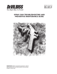
1
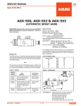
SB-E-DA-100-A
DA-100
LVMP
AUTOMATIC SPRAY GUN
OPERATION MANUAL
IMPORTANT:
Read and follow all instructions and SAFETY PRECAUTIONS before using this
equipment.
DESCRIPTION
DA-100 LVMP gun is developed to achieve high transfer efficiency and it can be obtained as well as
high atomization with less air consumption. LVMP stands for Low Volume Medium Pressure.
Small, lightweight LVMP gun is suitable for installing to automatic or semi-automatic machines.
Models and application information follows.
MODELS
Example:
DA - 100 - 20□−□□□
Basic Part No.
Fluid Tip Size 0.8, 1.1, 1.4, 1.8 mm
Air Cap No. 205, 207
NOTE: The gun body and fluid passage is made of Aluminum.
chlorinated solvents or waterborne paint.
Please do not use the gun with
Chart 1
Air Cap
Marking
Part No.
Fluid Tip Size
(mm)
Pattern Size
Shape
205
JJ-3-205
0.8, 1.1, 1.4, 1.8
250mm
Straight
Most conventional materials
207
JJ-3-207
0.8, 1.1, 1.4, 1.8
300mm
Straight
Most conventional materials
Chart 2
Air Cap
Tip Marking (mm)
205, 207
0.8
1.1
1.4
1.8
Part Number
(Tip & Needle Lapped Set)
DA-400-0.8
DA-400-1.1
DA-400-1.4
DA-400-1.8
− 1 −
Typical Applications
SAFTEY PRECAUSTIONS
This manual contains important information that ALL users should know and understand BEFORE using
this equipment. This information relates to USER SAFETY and PREVENTING EQUIPMENT PROBLEMS.
To help you recognize this information, we use the following terms to draw your attention to certain
equipment labels and portions of this manual. Pay special attention to any label or information that is
highlighted by one of these terms:
Important information to alert you to a situation that might cause serious injury or loss
WARNING
of life if instructions are not followed.
CAUTION
Important information that tells how to prevent damage to equipment.
NOTE
Information that you should pay special attention to.
WARNING
The following hazards may occur during the normal use of this equipment. Please read the following chart.
HAZARD
CAUSE
SAFEGUARDS
Fire
Solvents and coatings can be
1. Adequate exhaust must be provided to keep the air
highly flammable or
free of accumulations of flammable vapors.
combustible,
2. Smoking must never be allowed in spray area.
especially when sprayed.
3. Fire extinguishing equipment must be present in the
spray area.
4. Static discharges must be prevented. Ground (earth)
all conductive objects in the spray area, such as a
cleaning solvent bucket, fire extinguisher, etc.
5. When using solvents for cleaning;
・ Those used for equipment flushing must have a flash
point equal to or greater than that of the coating.
・ Those used for general cleaning must have flash
points above 100°F(37.8℃).
Inhaling Toxic
Certain materials may be 1. Follow the requirements of the Material Safety Data
Substances
harmful if inhaled, or if there
Sheet supplied by coating material manufacturer.
is contact with the skin.
2. Adequate exhaust must be provided to keep the air
free of accumulations of toxic materials.
3. Use a mask or respirator whenever there is a chance
of inhaling sprayed materials. The mask must be
compatible with the material being sprayed and its
concentration. Equipment must be as prescribed by
an industrial hygienist or safety expert, and be NIOSH
approved.
Explosion HazardHalogenated hydrocarbon
The T-AGB spray gun can be used with these
Incompatible
Solvents- for example:
solvents.
Materials.
methylene chloride and 1,1,1,
However, aluminum is widely used in other spray
-Trichloroethane are not
application equipment – such as material pumps,
chemically compatible with
cups, regulators, valves, etc.
the aluminum that might be
Check all other equipment items before use of these
used in many system
solvents. Read the label or data sheet for the
components. The chemical
material you intend to spray. If in doubt as to where
reaction caused by these
or not a coating or cleaning material is compatible,
solvents reacting with
contact your material supplier.
aluminum can become violent
and lead to an equipment
explosion.
− 2 −
HAZARD
CAUSE
SAFEGUARDS
General Safety
Improper operation or
maintenance may create a
hazard.
Noise Levels
The continuous A-weighted
sound pressure level of this
spray gun may exceed
85dB(A) depending on the air
cap/nozzle set-up being
used. Sound levels are
measured using an impulse
sound level meter and
analyzer, when the gun is
being used in a normal
spraying application. Details
of actual noise levels
produced by the various air
cap/nozzle set-ups are
available on request.
Spraying solvent
Pressured air/fluid passage
may be broken when
cleaning or flashing with
solvent.
The solvent may be harmful
if contacted with eyes.
Operators should be given adequate training in the
safe use and maintenance of the equipment (in
accordance with the requirements of NFPA-33,
Chapter 15 in U.S.). Users must comply with all
local and national codes of practice and insurance
company requirements governing
ventilation, fire precautions, operation, maintenance
and housekeeping (in the U.S., these are OSHA
Sections 1910.94 and 1910.107 and NFPA-33).
Wear earplugs when using the spray gun.
Always wear eye protection when spraying or
cleaning the equipment.
MISUES:
・All spray guns project particles at high velocity and must never be aimed t any part of body.
・Never exceed the recommended safe working pressure for any of the equipment used.
・The fitting of non-recommended or non-original accessories or spare parts may create hazardous
conditions.
・Before dismantling the equipment for cleaning or maintenance, all pressures, air and material, must be
isolated and released.
Disposal of non-metallic materials must be carried out in an approved manner. Burning may
generate
toxic fumes. The removal of waste solvents and coating materials should be carried out by an
authorised local waste disposal service.
− 3 −
SPECIFICATION
Max. Air Pressure:
Max. Fluid Pressure:
Cylinder Air Pressure:
Weight:
Gun Stud Diameter:
Fluid Thread:
CYL Thread:
0.69MPa (6.9 bar)
0.69MPa (6.9 bar)
Min. 0.35MPa (3.5 bar)
Max. 0.50MPa (5.0 bar)
480g
16.0mm
G1/4 (M)
CAP Thread:
G1/4 (M)
G1/4 (M)
INSTALLATION
Figure 1. Dimensions
Mount the gun with the set screw (22).
NOTE:
The air supplied to the gun should be clean air that removed any impurities. Also, the air hose
should have enough inner diameter depending on the length to supply necessary air.
OPERATIONS
1.Mix, prepare and strain the coating material to be sprayed according to paint manufacture’s instructions.
2.Adjust the CYL air at 0.35 Mpa ~. Please use air regulator for setting the air pressure for the smooth
movement of CYL.
3.Turn Needle Adjusting Knob counter-clockwise 3.5 turns from fully closed position. This makes the Needle
fully opened.
4.Adjust CAP air at 0.20Mpa.
5.Adjust fluid pressure at about 0.07Mpa~0.1Mpa.
6.Turn on CYL air and test spray. Adjust fluid and air pressure until desired pattern is obtained. Pattern size
can be adjusted by using pattern valve (5). Control fluid pressure at supply source. Always attempt to
keep CAP pressure as low as possible to minimize overspray and control the air at air supply source.
WARNING
Risk of injury. Equipment and fluid may be under pressure. Pressure in the system must be
relieved before beginning the cleaning procedure and before replacing any parts. Follow the
procedures in the literature provided with the system.
− 4 −
CLEANING
1.Relieve air pressure from pressure tank. Carefully follow instructions in bulletin sent with tank.
2.Replace material in container with a suitable solvent.
3.Repressurize system.
4.Trigger gun and repeat procedure until gun and hose are thoroughly clean. A SolventSaver TM type hose
and gun cleaner which supplies a mixture of air and solvent can be used to most effectively clean gun and
hose internal passages. See “Accessories” for SolventSaver TM .
5.Wipe exterior of gun with a solvent dampened cloth.
CAUTION
Do not totally submerge gun in solvent. It is possible for wash solids to flow into air operating
sections of gun which could seriously damage piston “O” Ring seals.
CAUTION
The air cap can be immersed in solvent for cleaning and brush the gun. If orifices are clogged,
use a broom straw or toothpick to remove obstruction. Never use a steel wire or hard instrument.
This will damage air cap and result in a distorted spray pattern.
REPLACEMENT
Tools Required
• Crescent Wrench or Spanner
• 19mm Box Wrench or Hex Wrench (for Item No. 4)
• Pliers (for Needle Assy)
• Large Minus Screw Driver
☆Fluid Tip, Fluid Needle (4), Needle Packing (6)
1. Relieve all air and fluid pressure in system.
2. Remove Retaining Ring (1) and Air Cap (2).
3. Remove Fluid Tip (3)
4. Replace Fluid Tip and Needle at the same time with the lapped set. It is recommended to replace
needle packing (6) at the same time as replacing the tip and needle.
5. Remove Ratchet Assy. (18) and Pull Needle Assy. out from gun body with Pliers.
6. Remove Cover (20), Packing Gland (7) and take out Needle Packing (6)
7. Reassemble in reverse order. It is recommended to put Gun lube (SSL-10) slightly between needle
and needle packing.
8. Recommended torque of Fluid Tip: 20~11N.m.
☆Piston Cup (13), Air Valve (11), O-Ring (8), Gasket (9)
1. Remove Ratchet Assy. (18) and Pull Needle Assy. out from gun body.
2. Screw Needle (from the rear side) in Piston Cup (13) and pull Needle to take out Piston Cup.
3. Turn Air Valve (11) counter-clockwise with proper tool putting in the slot and remove it.
4. Remove O-Ring (8) and Gasket (9).
5. Wipe the inside of cylinder and clean it. Apply non-silicone grease lightly on O-Ring.
6. Reassemble in reverse order.
☆Fluid Inlet (19), Air Connector (22)
1. When Remove Fittings and reassemble the gun, remove the sealing material from the gun body and
fittings completely.
2. Put the new sealing material (Loctite 242, etc.) on the thread part of fittings when reassemble.
− 5 −
Figure 5. Gun Exploded View
Parts Sheet
Ref No.
1
2
3
4
5
6
7
8
9
10
11
12
13
14
15
16
17
18
19
20
21
22
23
Part Number
JJ-6
JJ-50-K5
See Chart. 1
See Chart. 2
DA-44
DA-7-K10
DA-13-K3
DA-P9P16
DA-12
DA-P10-K5
DA-43
DA-Y20-K3
DA-9
DA-4993
DA-46-K5
3/16BALL-K5
DA-34
DA-402
FUN-35
DA-33
DA-2048
DA-30
PC6-02
PC8-02
Description
Retaining Ring (with seat)
Seat Kit of 5
Air Cap
Lapped Set (Fluid Tip & Needle)
Pattern Valve Assy.
Needle Packing Kit of 10
Packing Gland Kit of 3
O-Ring Kit
Air Valve Gasket
O-Ring Kit of 5
Air Valve Assy.
Y-Packing Kit of 3
Piston Assy.
Spring Kit
E-Ring Kit of 5
Ball Kit of 5
Ratchet Spring
Ratchet Assy.
Fluid Inlet
Cover
Set Screw
Air Connector
Quick Fitting Joint (24.7mm)
Quick Fitting Joint (26.6mm)
− 6 −
Qty
1
1
1
1
1
2
1
1
1
1
1
1
1
1
1
1
1
1
1
1
2
2
1
1
Remarks
With JJ-50
With DA-Y20
SERVICE CHECK
Normal Spray Pattern
The proper combination of fluid pressure, fan and atomization air pressure,
and fluid tip size should result in a pattern of this shape.
PROBLEM
Will not spray.
Improper spray
pattern.
Jerky or fluttering
spray.
Air leaking from
Adjusting Screw (20).
Dripping from Fluid
Tip.
Air or fluid leaking
from Gun Body (6).
CAUSE
CORRECTION
No pressure to gun.
Piston stops moving.
A.
Gun not adjusted properly.
A, B Material build up on the air
cap (2)or fluid tip (3).
Check air and material lines.
Check CYL air pressure.
A.
Re-adjust. See “Operation
Section”.
A, B Clean the air cap or fluid tip.
See “Preventive Maintenance”.
Note
To determine where the material build up is, rotate the air cap 180°and test
spray. If the pattern stays in the same position, the condition is caused by
material build up on the fluid tip. If the pattern changes with air cap movement,
the build up is in the air cap.
C, D. Wrong material or material
C, D Adjust material pressure or thin
too thick.
material.
Insufficient material or
Increase material or reduce
atomizing air pressure too
atomizing air pressure.
high.
1. Insufficient material in the tank
1. Fill tank or clear obstruction.
or an obstruction in the line.
2. Gun material passage plugged.
2. Clean.
3. Worn Needle Seal Kit (7).
3. Replace.
4. Loose or damaged fluid tip.
4. Tighten or replace.
1. Damaged or worn Piston Cup 1. Replace.
(14).
2. Damaged cylinder of Gun Body 2. Replace.
(6).
1. Worn or damaged Fluid Tip (2)
1. Replace.
or Needle (12).
2. Needle Spring (18) damaged or
2. Replace.
3. deformed.
Damaged or worn Needle Seal Kit Replace.
(7)
ACCESSORIES
PART NUMBER
SSL-10
42884-214-K5
AGA-415
GC-100-K48
HD-505
QMGZ-5200
DESCRIPTION
Gun Lube (60ml)
Cleaning Brush (Kit of 5)
Universal Clamp
Gun Cover (Kit of 48)
Quick Cleaner (5L)
Solvent Saver (10L)
− 7 −