1
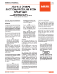
SERVICE MANUAL EN ■ Major Repair Kit KK-4987-2 JGA-510 CONVENTIONAL SPRAY GUN IMPORTANT: Before using this equipment, read all safety precautions and instructions. Keep for future use. DESCRIPTION The JGA-510 can be utilized with the wide range of air caps and needles. It is a general purpose, heavy duty, high production spray gun suitable for use with most types of materials. The fluid tip and needle and internal fluid passages are stainless steel. Conversion to HVLP - The JGA-510, plus JGA-503 models, can be converted to HVLP if desired. Contact DeVilbiss for information. Note This gun includes 300 series stainless steel fluid passages and 300/400 series tip and needle. Guns may be used with chlorinated solvent materials, but see page 2 for additional warnings. Important: This gun may be used with most common coating and finishing materials. It is designed for use with mildly corrosive and non-abrasive materials. If used with other high corrosive or abrasive materials, it must be expected that frequent and thorough cleaning will be required and the necessity for replacement of parts will be increased. OPERATION Note Protective coating and rust inhibitors have been used to keep the gun in good condition prior to shipment. Before using the gun, flush it with solvent so that these materials will be removed from fluid passages. Strain material thru 60 or 90 mesh screen. Adjust fluid pressure to deliver the desired paint volume. Adjust air pressure and flow to provide a uniform dispersion of atomized paint throughout the pattern. Keep air pressure as low as possible to minimize bounce - back and overspray. Excessive fluid flow will result in heavy center spray patterns. Inadequate flows may cause the pattern to split. See “Troubleshooting”, Page 6, if any problems occur. SB-2-252-N (8/2014) PREVENTIVE MAINTENANCE SPRAY GUN LUBRICATION To clean air cap and fluid tip, brush exterior with a stiff bristle brush. If necessary to clean cap holes, use a broom straw or toothpick. Never use a wire or hard instrument. This may scratch or burr holes causing a distorted spray pattern. Daily, apply a drop of SSL-10 spray gun lube at trigger bearing stud (21) and the stem of the air valve (13) where it enters the air valve assembly (17). The shank of the fluid needle (33) where it enters the packing nut (19) should also be oiled. The fluid needle packing (18) should be lubricated periodically. Make sure the baffle (6) and retaining ring (1 or 2 ) threads are clean and free of foreign matter. Before assembling retaining ring to baffle, clean the threads thoroughly, then add two drops of SSL-10 spray gun lube to threads. The fluid needle spring (30) and air valve spring (12) should be coated with a very light grease, making sure that any excess grease will not clog the air passages. For best results, lubricate the points indicated, daily. To clean fluid passages, remove excess material at source, then flush with a suitable solvent using a device such as the SolventSaver™ (see Accessories). Wipe gun exterior with a solvent dampened cloth. Never completely immerse in solvent as this is detrimental to the lubricants and packings. Note When replacing the fluid tip or fluid needle, replace both at the same time. Using worn parts can cause fluid leakage. Also, replace the needle packing at this time. Lightly lubricate the threads of the fluid tip before reassembling. Torque to 20-25 ft. lbs. Do not overtighten the fluid tip. A. Trigger Points B.Packing C. Adjusting Valves D. Baffle Threads E. Air Valve Cartridge A C To prevent damage to the fluid tip (4) or fluid needle (33), be sure to either 1) pull the trigger and hold while tightening or loosening the fluid tip or 2) remove fluid needle adjusting screw (28) to relieve spring pressure against needle collar. D B E FLUID INLET GASKET (7) REPLACEMENT INSTRUCTIONS 1. Remove fluid inlet adapter with appropriate wrench. 2. Clean Loctite from gun body inlet threads and seal area. 3. Place gasket (7) squarely onto the fluid inlet adapter and push it down until it is flat against the boss. 4. Place a couple of drops of medium strength blue No. 242 Loctite on threads before installing fluid inlet adapter. 5. Torque fluid inlet adapter to 20-25 ft. lbs., and tighten locknut. ■ Government NSN No. 4940-01-046-9919 = KK-4987-2. 1/8 EN SAFETY PRECAUTIONS This manual contains information that is improtant for you to know and understand. This information relates to USER SAFETY and PREVENTING EQUIPMENT PROBLEMS. To help you recognize this information, we use the following symbols. Please pay particular attention to these sections. Note Important safety information - A hazard that may cause serious injury or loss of life. Important information that tells how to prevent damage to equipment, or how to avoid a situation that may cause minor inury. Information that you should pay special attention to. The following hazards may occur during the normal use of this equipment. Please read the following chart before using this equipment. HAZARD CAUSE SAFEGUARDS Fire Solvent and coatings can be highly flammable Adequate exhaust must be provided to keep air free of or combustible especially when sprayed. accumulations of flammable vapors. Smoking must never be allowed in the spray area. Fire extinguishing equipment must be present in the spray area. Solvent Spray Inhaling Toxic Substances During use and while cleaning and flushing, solvents can be forcefully expelled from fluid and air passages. Some solvents can cause eye injury. Wear eye protection. Certain materials may be harmful if inhaled, or if there is contact with the skin. Follow the requirements of the Material Safety Data Sheet supplied by your coating material manufacturer. Adequate exhaust must be provided to keep the air free of accumulations of toxic materials. Use a mask or respirator whenever there is a chance of inhaling sprayed materials. The mask must be compatible with the material being sprayed and its concentration. Equipment must be as prescribed by an industrial hygienist or safety expert, and be NIOSH approved. Explosion Hazard - Halogenated hydrocarbon solvents - for Incompatible example; methylene chloride and 1, 1, 1 - Materials Trichloroethylene are not chemically com- patible with the aluminum that might be used in many system components. The chemical reaction caused by these solvents reacting with aluminum can become violent and lead to an equipment explosion. General Safety Improper operation or maintenance of equipment. Guns with stainless steel internal passageways may be used with these solvents. However, aluminum is widely used in other spray application equipment - such as material pumps, regulators, valves and cups. Check all equipment items before use and make sure they can also be used safely with these solvents. Read the label or data sheet for the material you intend to spray. If in doubt as to whether or not a coating or cleaning material is compatible, contact your material supplier. Operators should be given adequate training in the safe use & maintenance of the equipment (in accordance with the require ments of NFPA-33, Chapter 15). Users must comply with all local and national codes of practice and insurance company require ments governing ventilation, fire precautions, operation, maintenance and housekeeping. These are OSHA Sections 1910.94 and 1910.107 and NFPA-33. Cumulative Trauma Use of hand tools may cause cumulative Pain, tingling, or numbness in the shoulder, forearm, wrist, Disorders (“CTD’s”) trauma disorders (“CTD’s”). hands or fingers, especially during the night, may be early symptoms of a CTD. Do not ignore them. Should you experience CTD’s, or musculo- CTD's when using hand tools, tend to affect any such symptoms, see a physician immediately. Other early skeletal disorders, the upper extremities. Factors which may symptoms may include vague discomfort in the hand, loss of involve damage to increase the risk of developing a CTD include: manual dexterity, and nonspecific pain in the arm. Ignoring early the hands, wrist, symptoms and continued repetitive use of the arm, wrist and elbows, shoulders, 1. High frequency of the activity. hand can lead to serious disability. Risk is reduced by avoiding neck & back. Carpal 2. Excessive force, such as gripping, pinching, or lessening factors 1-7. tunnel syndrome & or pressing with the hands and fingers. tendinitis (such as 3. Extreme or awkward finger, wrist, or arm tennis elbow or positions. rotator cuff syndrome) 4. Excessive duration of the activity. are examples of 5. Tool vibration. CTD’s. 6. Repeated pressure on a body part. 7. Working in cold temperatures. CTD’s can also be caused by such activities as sewing, golf, tennis bowling, to name a few. 2/8 SB-2-252-N (8/2014) EN CHART 1 NOZZLE COMBINATIONS Air Cap Sizes Order From Chart 2 Fluid Tip and Needle Size Order From Chart 3 AC D E EE EX FF FX FW GX Tip Orifice in./ .110.080.070.070.070.055 .042.063.034 mm 2.82.21.81.81.81.4 1.11.6 .9 24 P P P 30 P S S S S 58S PPP 62HD P 64HD P 67HDP 69HD P 80S S SS 704PPP 765PPP 777PP 797PP 9000S SS S P = Pressure Feed Combination S = Suction Feed Combinations CHART 2 No. on Cap Order ➞ CHART 3 FLUID TIPS AND NEEDLES Tip Orifice Size In. / (mm) Ref. No. 4 Fluid Tip Ref. No. 33 Fluid Needle 303 GR. S.S. TIPS AND 303 GR. S.S. NEEDLES .110 (2.8) AV-2115-AC JGA-402-C .086 (2.2) AV-2115-D JGA-402-DEX .070 (1.8) AV-2115-E JGA-402-E .070 (1.8) AV-2115-EX JGA-402-DEX .055 (1.4) AV-2115-FF JGA-402-FF .042 (1.1) AV-2115-FX JGA-402-FX .063 (1.6) AV-2115-FW JGA-402-FF .034 (.9) AV-2115-GX 24 30 MB-4039-30 58 AV-439-58 62HD MB-4039-62HD 64HD MB-4039-64HD 67HD MB-4039-67HD 69HD MB-4039-69HD 80 MB-4039-80 704 765 777 797 9000 AV-440-9000 OPTIONAL 300 GR. S.S. W/ U.H.M.W. POLYETHYLENE NEEDLE SEAT AV-4915-D --- .070 (1.8) AV-4915-E --- .055 (1.4) AV-4915-FF --- .042 (1.1) AV-4915-FX --- .028 (.8) AV-4915-G --- OPTIONAL CARBOLOY TIPS AND NEEDLES .086 (2.2) AV-1415-D JGA-409-D .070 (1.8) AV-1415-EE JGA-409-DEEE .055 (1.4) AV-1415-FF JGA-409-FF SB-2-252-N (8/2014) Ref. No. (3) Air Cap Less Ring* AV-40-24 AV-1239-704 AV-1239-765 31767-777 AV-1239-797 *MBC-368 Retaining Ring (sold separately) is required to mount Air Cap to Gun. --- .086 (2.2) AIR CAPS Ref. No. (1) Air Cap With Ring 3/8 EN PARTS LIST Ref. No. Replacement Part No. Description 1 See Chart 2 2 MBC-368 3 See Chart 2 4 See Chart 3 *5 GTI-33-K5 6 GTI-425 7 MSV-3-K10 8 --- 9 --- 10 JGA-4044 *11 JGS-72-K10 *12 MBD-12-K25 *13 JGS-431-K25 *14 JGS-26-K25 *15 JGA-15-K25 *16 JGA-14-K25 17 JGS-449-1 *18 JGV-463-K3 19 34411-122-K10 *20 --- 21 JGS-478 22 JGS-477-1 23 JGA-132 24 P-MB-51 25 JGA-497-1 *26 --- *27 SSG-8069-K25 28 JGS-16 *29 --- *30 MBD-19-K10 31 --- 32 JGA-4041 33 See Chart 3 34 --- Individual Parts Required Air Cap w/ Retaining Ring Retaining Ring Air Cap Less Retaining Ring Fluid Tip Seal Kit (Kit of 5) Baffle Assembly Fluid Inlet Gasket (Kit of 10) PTFE (blue) Lock Nut Fluid Inlet Adapter Fluid Inlet and Nut Kit Gasket Kit (Kit of 10) (PTFE) Spring Kit (Kit of 25) Air Valve Kit (Kit of 25) U Cup Seal Kit (Kit of 25) Washer Kit (Kit of 25) Snap Ring Kit (Kit of 25) Air Valve Assembly Packing Kit (Kit of 3) Packing Nut Kit (Kit of 10) Screw Stud and Screw Kit (Kit includes 3 studs and 5 screws) Trigger, Stud and Screw Kit (Kit includes 1 each) Plug Nipple Fan Adjustment Assembly Retaining Ring O-Ring (Viton) (Kit of 25) Adjusting Screw Spring Pad (Included with # 30 and 32) Spring Kit (Kit of 10) Bushing Bushing, Spring Pad and Knob Kit Fluid Needle Gun Body 1 1 1 1 1 1 1 1 1 1 2 1 1 1 1 1 1 1 1 1 1 1 1 1 1 1 1 1 1 1 1 1 1 1 * A quantity of necessary parts is included in Major Repair Kit KK-4987-2 for complete gun repair and should be kept on hand for service convenience. Suffixes - K10 designates kits of multiple parts. (Example) JGS-72-K10 is a kit of 10 gaskets. ■ Government NSN No. 4940-01-046-9919 = KK-4987-2. GTI-33 Baffle Seal Replacement (5) 1. Remove fluid tip (4). 2. Remove baffle (6). 3. Remove seal (5) from baffle. 4. Assemble seal to baffle with angled side up as shown at right. 5. Install baffle on gun. 6. Install fluid tip (4) and tighten to 12-15 ft-lbs. NOTE The seal is designed to be a tight fit on the baffle. The seal should be able to be removed using your fingers. If you are unable to remove the seal using your fingers, insert a small screwdriver between the outer lip and the back of the baffle and pry the seal off. The seal should be a tight fit on the baffle. If it is a loose fit on the baffle, assure that it is assembled with the angled side up. ANGLED SIDE SEAL NOTE 4/8 THICK SIDE Pry here if necessary BAFFLE SB-2-252-N (8/2014) EN 32 33 11 31 30 29 28 25 2 6 See GTI-33 Baffle Seal Replacement Instructions on Page 4. 4 1 27 26 3 5 7 Torque to 12-15 ft. lbs. 34 8 * Torque to 20-25 ft. lbs. 9 10 Δ 18 19 Fluid Inlet Nipple 3/8 NPS (M) * 24 20 16 15 14 13 12 *23 11 21 Air Inlet Nipple 1/4 NPS (M) Torque to 15 ft. lbs. 17 Δ Detail Ref. No. 18 - Two piece packing covered by U.S. Patent No. 5,209,501. + Tapered edge faces out towards packing nut. +Inner PTFE Piece Outer U.H.M.W. Poly. Piece SB-2-252-N (8/2014) 22 Fluid Packing Nut Fluid Needle *Apply QH-130 (Loctite #242 med. strength blue) sealing compound on threads. 5/8 EN TROUBLESHOOTING CONDITION CAUSE CORRECTION Heavy top or bottom pattern Horn holes plugged. Obstruction on top or bottom of fluid tip. Cap and/or tip seat dirty. Clean. Ream with non-metallic point. Clean. Clean. Heavy right or left side pattern Left or right side horn holes plugged. Dirt on left or right side of fluid tip. Clean. Ream with non-metallic point. Clean. Remedies for the top-heavy, bottom-heavy, right-heavy and left-heavy patterns: 1) Determine if the obstruction is on the air cap or the fluid tip. Do this by making a test spray pattern. Then, rotate the cap one-half turn and spray another pattern. If the defect is inverted, obstruction is on the air cap. Clean the air cap as previously instructed. 2) If the defect is not inverted, it is on the fluid tip. Check for a fine burr on the edge of the fluid tip. Remove with #600 wet or dry sand paper. 3) Check for dried paint just inside the opening. Remove paint by washing with solvent. Heavy center pattern Fluid pressure too high for atomization air (pressure feed). Material flow exceeds air cap's capacity. Atomizing pressure too low. Material too thick. Balance air and fluid pressure. Increase spray pattern width with spreader adjustment valve. Thin or lower fluid flow. Spreader adjustment valve set too low. Adjust. Increase pressure. Thin to proper consistency. Split spray pattern Atomization air pressure too high. Fluid pressure too low (pressure feed only). Spreader adjusting valve set too high. Reduce at transformer or gun. Increase fluid pressure (increases gun handling speed). Adjust. Jerky or fluttering spray *Loose or damaged fluid tip/seat. Material level too low. Container tipped too far. Obstruction in fluid passage. Loose or broken fluid tube or fluid inlet nipple. Dry or loose fluid needle packing nut. Tighten or replace. Refill. Hold more upright. Backflush with solvent. Tighten or replace. Lubricate or tighten. Unable to get round spray Spreader adjustment screw not seating properly. Air cap retaining ring loose. Clean or replace. Tighten. Will not spray No air pressure at gun. Internal mix or pressure feed air cap and tip used with suction feed. Fluid pressure too low with internal mix cap and pressure tank. Fluid needle adjusting screw not open enough. Fluid too heavy for suction feed. Check air supply and air lines. Change to proper suction feed air cap and tip. Increase fluid pressure at tank. Open fluid needle adjusting screw. Thin material or change to pressure feed. Starved spray pattern Inadequate material flow. Low atomization air pressure (suction feed). Back fluid adjusting screw out to first thread or increase fluid pressure at tank. Increase air pressure and rebalance gun. Excessive overspray surface. Excessive fog Too much atomization air pressure Gun too far from work surface. Improper stroking (arcing, gun motion too fast). Reduce pressure. Adjust to proper distance. Move at moderate pace, parallel to work Too much, or too fast-drying thinner. Too much atomization air pressure. Remix properly. Reduce pressure. Dry Spray Air pressure too high. Gun tip too far from work surface. Gun motion too fast. Gun out of adjustment. Reduce air pressure. Adjust to proper distance. Slow down. Adjust. Fluid leaking from packing nut Packing nut loose. Packing worn or dry. Tighten, do not bind needle. Replace or lubricate. Fluid leaking or dripping from front of pressure feed gun Packing nut too tight. Dry packing. Fluid tip or needle worn or damaged. Foreign matter in tip. Fluid needle spring broken. Wrong size needle or tip. Adjust Lubricate. Replace tip and needle with lapped sets. Clean. Replace. Replace. *Most common problem. 6/8 SB-2-252-N (8/2014) EN TROUBLESHOOTING (continued) CONDITION CAUSE CORRECTION Runs and sags Too much material flow. Material too thin. Gun tilted on an angle, or gun motion too slow. Thin, sandy coarse finish Gun too far from surface. drying before it flows out Too much air pressure. Improper thinner being used. Check distance. Normally approximately 8". Reduce air pressure and check spray pattern. Follow paint manufacturer's mixing instructions. Thick, dimpled finish "orange peel". Check distance. Normally approximately 8". Increase air pressure or reduce fluid pressure. Increase air pressure or reduce fluid pressure. Follow paint manufacturer's mixing instructions. Follow paint manufacturer's mixing instructions. Properly clean and prepare surface. Adjust gun or reduce fluid pressure. Mix properly or apply light coats. Hold gun at right angle to work and adapt to proper gun technique. Gun too close to surface. Too much material coarsely atomized. Air pressure too low. Improper thinner being used. Material not properly mixed. Surface rough, oily, dirty. ACCESSORIES P-H-5516 Air Adjusting Valve HAV-500 or HAV-501 Adjusting Valve HD-503 SolventSaver™ Hose/Gun Cleaner HARG-510 Air Regulator JGA-4035-K5 Optional 3 Piece Packings JGA-52-K10 Leather Packings This 3 piece packing can be used in place of Ref. (18) JGV-463, 2 piece packing. Used when abrasive materials are sprayed (i.e. porcelain enamel). Use (2) JGA-52 packings in place of JGV-463 packing. Spray Gun Lube SSL-10 (2 oz. bottle) MSA-4-K10 Fluid Needle Spring (replaces MBD-19) (HAV-501 SHOWN) HAV-500 does not have pressure gage. Use to control air usage at gun. 2 Qt Hose/Gun Cleaner used to clean the inside of hose, fluid passageways of gun & other paint equipment. Cleaning Brushes VS-531 Low Pressure Strainers 83GZ-5200 SolventSaver™ Hose/Gun Cleaner These brushes are helpful in cleaning threads and recesses of gun body. The VS-531 Low Pressure Fluid Strainer provides a final filter for trapping foreign particles in the paint supply. Enables user to control and reduce air usage at the gun. Ideal for low pressure spraying. 42884-214-K5 3/8" 42884-215-K10 5/8" JGA-156-K10 Spring Clip HAF-507 Whirlwind™ In-Line Air Filter Use to maintain nearly constant outlet pressure despite changes in inlet pressure and downstream flow. GTI-415 Air Adjusting Valve Installs into gun to enable user to control and reduce air usage at the gun. Replaces JGA-132 plug. 2 Gallon galvanized tank used to clean the inside of hose and material passages of the gun. Quick Disconnect Approved for HVLP Guns (Air) High Flow Ball and Ring Type Compatible with all paint materials: contains no silicone or petroleum distillates to contaminate paint. MSDS sheet available upon request. KB-555 (Aluminum) & KB-545-SS (S/S) 2 qt. Pressure Feed Cup With Regulator Provides reduced spring force (4 lbs. verses 6 lbs.) for easier trigger pull. JGA-191-K2 Heavy Duty Spring (for zinc rich materials) HC-4419 1/4" NPS(F) Joins any single piece DeVilbiss air cap MBC368 or MSA-1 retaining ring. Helps prevent parts loss and provides easier assembly. Removes water, oil, and debris from the air line. TGC-545 (Aluminum) TLC-555 (Non-stick Lined) TSC-595 S.S. 2 Qt. Drip-Free Suction Cup Cup has a unique, two position valve which permits selection of either a drip-free or conventional open vent mode. JGA-444 Fluid Tube This tube combines the fluid and air hoses at gun handle preventing dragging hoses over work, twisting line and improving overall gun handling. SB-2-252-N (8/2014) HC-4699 1/4" NPT(M) HC-4700 1/4" NPT(F) HC-1166 1/4" NPT(M) TLC-576 Aluminum Cup (Non-stick Lined) & TSC-591Stainless Steel Cup Provides greater degree of control over cup fluid pressure. 29-3100 Scrubs® Millennium 3000 Hand Cleaner Towels Twin Cartridge Paint Spray Respirator Scrubs® are a premoistened hand cleaner towel for painters. No water is needed. NIOSH-Certified, for respiratory protection in atmospheres not immediately dangerous to life. 1 Qt. pressure feed cups. 3/8" NPS (F), cam lock lid. Requires KK-4980 air regulator kit. WR-103 Wrench Contains all necessary tip, hose and nut sizes used on or with gun. 7/8 EN WARRANTY POLICY DeVilbiss products are covered by Finishing Brands one year materials and workmanship limited warranty. The use of any parts or accessories, from a source other than Finishing Brands, will void all warranties. For specific warranty information please contact the closest Finishing Brands location listed below. Finishing Brands reserves the right to modify equipment specifications without prior notice. DeVilbiss, Ransburg, BGK, and Binks are registered trademarks of Finishing Brands. ©2014 Finishing Brands. All rights reserved. DeVilbiss is part of Finishing Brands, a global leader in innovative spray finishing technologies. For technical assistance or to locate an authorized distributor, contact one of our international sales and customer support locations below. USA/Canada www.devilbiss.com [email protected] Tel: 1-800-992-4657 Fax: 1-888-246-5732 Mexico www.finishingbrands.com.mx [email protected] Tel: 011 52 55 5321 2300 Fax: 011 52 55 5310 4790 Brazil www.devilbiss.com.br [email protected] Tel: +55 11 5641 2776 Fax: 55 11 5641 1256 United Kingdom www.finishingbrands.eu [email protected] Tel: +44 (0)1202 571 111 Fax: +44 (0)1202 573 488 France www.finishingbrands.eu [email protected] Tel: +33(0)475 75 27 00 Fax: +33(0)475 75 27 59 Germany www.finishingbrands.eu [email protected] Tel: +49 (0) 6074 403 1 Fax: +49 (0) 6074 403 281 China www.finishingbrands.com.cn [email protected] Tel: +8621-3373 0108 Fax: +8621-3373 0308 Japan www.ransburg.co.jp [email protected] Tel: 081 45 785 6421 Fax: 081 45 785 6517 Australia www.finishingbrands.com.au [email protected] Tel: +61 (0) 2 8525 7555 Fax: +61 (0) 2 8525 7500 8/8 SB-2-252-N (8/2014)