1
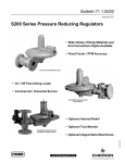
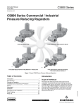
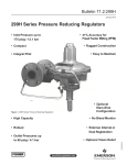
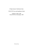
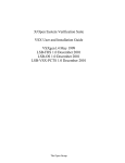
VSX4 and VSX8 Series
Instruction Manual
Form 5867
January 2015
VSX4 and VSX8 Series Controller
Table of Contents
Introduction . . . . . . . . . . . . . . . . . . . . . . . . . . . . . . . . .1
Specifications . . . . . . . . . . . . . . . . . . . . . . . . . . . . . . .2
Principle of Operation . . . . . . . . . . . . . . . . . . . . . . . . .5
Installation . . . . . . . . . . . . . . . . . . . . . . . . . . . . . . . . . .6
Dimensions . . . . . . . . . . . . . . . . . . . . . . . . . . . . . . . . .7
Startup and Shutdown . . . . . . . . . . . . . . . . . . . . . . . . .8
Commissioning . . . . . . . . . . . . . . . . . . . . . . . . . . . . . .8
Controller Spring Adjustment . . . . . . . . . . . . . . . . . . . .8
Maintenance . . . . . . . . . . . . . . . . . . . . . . . . . . . . . . . .9
TyPE VSX8
Parts Ordering . . . . . . . . . . . . . . . . . . . . . . . . . . . . . .14
Parts List . . . . . . . . . . . . . . . . . . . . . . . . . . . . . . . . . .14
WarNINg
Failure to follow these instructions or
to properly install and maintain this
equipment could result in an explosion
and/or fire causing property damage and
personal injury or death.
Fisher® controller must be installed,
operated and maintained in accordance
with federal, state and local codes, rules
and regulations and Emerson Process
Management Regulator Technologies,
Inc. (Emerson™) instructions.
TyPE VSX4
Figure 1. VSX4 and VSX8 Series Controller
The VSX4 and VSX8 Series controller do
not activate in response to fire, seismic
and lightning events.
Only a qualified person must install
or service the VSX4 and VSX8 Series
controller. If a leak develops or if the
controller continually vents gas, service
to the unit may be required. Failure
to correct trouble could result in a
hazardous condition.
Introduction
Installation, operation and maintenance
procedures performed by unqualified
personnel may result in improper
adjustment and unsafe operations which
may result in equipment damage or
personal injury.
This Instruction Manual provides installation,
adjustment, maintenance and parts ordering
information for the VSX4 and VSX8 Series controller.
Instructions for other equipment used with the
controller, such as pressure regulators, can be found
in separate instruction manuals.
Scope of the Manual
www.fisherregulators.com
D103127X012
!
VSX4 and VSX8 Series
Specifications
The Specifications section lists the specifications for the VSX4 and VSX8 Series controller. The following information
is stamped on the nameplate of VSX4 and VSX8 Series: Type and Class, Maximum Outlet Pressure and Spring
Range. Additional operating information is located on the Regulator nameplate.
Available Configurations
Types VSX4L and VSX8L: Low-pressure
controller which can be integrated into a regulator;
with 10 to 1100 mbar / 0.15 to 16 psig downstream
pressure and with either internal or external
pressure registration for the regulator.
Type VSX4H and VSX8H: High-pressure
controller which can be integrated into a
regulator; with 1100 to 4000 mbar / 16 to 58 psig
downstream pressure and with either internal or
external pressure registration for the regulator.
Controller Type
DS: Differential Strength
IS: Integral Strength
Functional Class
A: Min, Min and Max Installation
B: Max Installation Only
Connections
Controller Vent: 1/4 NPT
External Sensing Line: 1/4 NPT
Maximum Allowable Pressure (PS)(1)
Differential Strength: 20.0 bar / 290 psig
Integral Strength: 6.0 bar / 87 psig
Specific Maximum Allowable Pressure (PSd)(1)
6.0 bar / 87 psig
Maximum Inlet Pressure (Pumax)(1)
Differential Strength (DS): 16.0 bar / 232 psig
Integral Strength (IS): 6.0 bar / 87 psig
Valve Plug Size
Medium Capacity Body (MC) Ø:
24 mm / 0.94 in.
High Capacity Body (HC) Ø:
39 mm / 1.54 in.
Operating Temperature (TS)(1)
According to PED Standards
-20 to 66°C / -4 to 150°F
Non-PED: -30 to 66°C / -22 to 150°F
Casing Material
Aluminum
Response Time (ta)
< 1 second
Resetting Trip Mechanism
Manually after Fault Rectification
Position Indicator
Extended stem visible in center of reset button
Pressure Registration
Internal or External
European EN Reference Standard
EN 14382
Approximate Shipping Weights
Type VSX4L/VSX8L: 1.4 kg / 3.1 lbs
Type VSX4H: 1.5 kg / 3.2 lbs
Options
• Wire Seal - The VSX4 and VSX8 Series can
be ordered with an optional tamper-proof lock
wire to preclude unauthorized access to the
adjustment springs.
• Limit switch (inductive contact available only
on Type VSX8) - An optional remote notification
switch can be installed offering the capability to
remotely notify the operator should Type VSX8
shuttoff occur.
Pressure Drop
2
Q
Pu – Pu2 – 4
1.05 x Cg
ΔP =
2
1. The pressure/temperature limits in this Instruction Manual or any applicable standard limitation should not be exceeded.
Product Description
The VSX4 and VSX8 Series controller are designed to
shut off the flow of gas to the downstream system in the
event of outlet pressure rising above or falling below the
predefined levels.
• The VSX4 and VSX8 Series controller can be
mounted on various types of Emerson™ regulator.
It can also be mounted as a stand alone slam-shut
valve mounted in a Type VS100 body.
• The VSX4 and VSX8 Series can be integrated in
a slam-shut Type VS100 installed upstream of the
associated regulator.
• The VSX4 and VSX8 Series offer either internal or
external pressure sensing line, depending on the
regulator type and/or the specified conditions.
• The VSX4 and VSX8 Series controller are
equipped with an integral and automatic bypass.
2
VSX4 and VSX8 Series
VSX4L
VSX4H
VSX8L
IS
DS
6 bar
16 bar
LP
HP
1.5 bar
5.5 bar
A Min, Min and
Max installation
B Max installation
only
IS
DS
PS 6 bar Pumax 6 bar
PS 20 bar Pumax 16 bar
PSD 6 bar
PSD 6 bar
Pressure range following
service condition
Figure 2. EN 14382-VSX4/VSX8 Series Label
Table 1. VSX4 and VSX8 Series Overpressure Shutoff (OPSO) Spring Ranges
REGULATOR SETPOINT
Nominal
Minimum
Maximum
mbar
psig
mbar
psig
mbar
psig
SLAM SHUT
Spring Range
Type
Part Number
Overpressure Shutoff (OPSO) Range(1)(2)
OPSO Spring
10
0.15
20
0.29
30
0.44
30 to 60 mbar / 12 to 25 in. w.c.
GF02168X012
> 30
0.44
35
0.51
50
0.73
40 to 110 mbar / 16 to 43 in. w.c.
GF02169X012
> 50
0.73
60
0.87
80
1.16
60 to 190 mbar / 25 to 75 in. w.c.
GF02170X012
> 80
1.16
100
1.45
130
1.89
95 to 280 mbar / 1.4 to 4.1 psig
GF02171X012
> 130
1.89
160
2.32
250
3.63
> 250
3.63
300
4.35
400
5.80
140 to 500 mbar / 2.0 to 7.3 psig
GF02172X012
> 400
5.80
500
7.25
700
10.2
> 700
10.2
1000
14.5
1100
16.0
> 1100
16.0
1250
18.1
1500
21.8
> 1500
21.8
2000
29.0
2500
36.3
VSX4L,
VSX8L
400 to 1450 mbar / 5.8 to 21.0 psig
GF04353X012
0.90 bar to 3.0 bar / 13.1 to 43.5 psig
GF02173X012
1.6 to 5.5 bar / 23.2 to 79.8 psig
GF04353X012
VSX4H
> 2500
36.3
3000
43.5
4000
58.0
1. OPSO spring range for OPSO installation only.
2. When selecting OPSO set points, the outlet pressure rating of the regulator should be considered.
Table 2A. VSX4 and VSX8 Series Combined Overpressure and Underpressure Shutoff (OPSO and UPSO) Spring Ranges
for Types CSB404, CSB604 and CSB704
regulator
Minimum
Maximum
mbar
psig
mbar
psig
17
0.25
24
0.35
24
35
0.35
0.51
35
60
0.51
0.87
54
0.78
100
1.5
100
1.5
160
2.3
160
2.3
300
276
4
500
7.3
1000
14.5
spring range
Typical Setpoint
20
0.29
10
0.15
21
0.3
11
0.26
27
0.39
14
0.2
30
0.44
15
35
0.5
18
50
0.7
25
0.36
60
0.87
30
75
1.1
38
100
1.5
50
0.73
2.2
2.3
4.4
300
4.4
517
7.5
500
7.3
1000
14.5
1000
14.5
1200
17.4
1500
21.6
2000
29
3000
43.5
4000
58
mbar
5 to
30
VSX4L,
VSX8L
VSX4H,
VSX8H
10 to
75
psig
Factory Set
psig
150
43.5
Spring Range
mbar
160
3000
type
Under Pressure Shutoff Upso
0.07 to
0.44
0.15 to
1.1
25 to
159
0.36 to
2.3
100 to
500
1.5 to
7.3
100 to
750
1.5 to
10.9
500 to
2000
7.3 to
29
500 to
2800
7.3 to
40.6
mbar
psig
Over Pressure Shutoff Opso
Spring Range
Factory Set
mbar
psig
mbar
43
0.62
30 to
60
0.4 to
0.9
45
0.65
51
0.74
0.22
57
0.83
0.26
67
1
90
1.3
0.44
108
1.57
0.54
1.85
170
2.47
50 to
130
0.7 to
1.9
psig
95 to
270
1.4 to
3.9
128
150 to
380
2.2 to
5.5
248
3.6
264
3.83
75
1.1
80
1.2
150
2.2
260 to
600
3.8 to
8.7
450
6.53
250
3.6
400 to
1100
5.8 to
16
700
10.2
500
7.3
800 to
1600
11.6 to
23.2
1320
19.2
600
8.7
1100 to
2000
16 to
29
1600
23.2
1700 to
3700
24.7 to
53.7
2800 to
5500
40.6 to
79.8
750
10.9
1000
14.5
1500
21.8
2000
29
Spring part number
and color
1900
27.6
2400
34.8
3400
49.3
4400
63.8
UPSO
ERAA05835AO
White
OPSO
GF02167X012
Black
GF02168X012
Brown
T14169T0012
Blue
T14170T0012
Silver
FA142869X12
Orange Stripe
T14171T0012
Olive
FA142869X12
Orange Stripe
T14171T0012
Olive
GF02169X012
Red
GF02170X012
Orange
GF02171X012
Pink
GF02172X012
Green
GF02173X012
Silver
GF02171X012
Pink
GF02172X012
Green
GF02173X012
Silver
3
VSX4 and VSX8 Series
Table 2B. Type VSX8L Combined Overpressure and Underpressure Shutoff (OPSO and UPSO) Spring Ranges for Type CS804
REGULATOR
controller
Spring Range
Minimum
mbar
14
20
25
35
69
100
170
345
Maximum
In. w.c.
5.5
8
10
14
1 psig
1.5 psig
2.5 psig
5 psig
mbar
21
30
40
75
170
240
380
690
Under Pressure
Shut‑off (UPSO)
Set Range UPSO
mbar
In. w.c.
Type
In. w.c.
8.5
12
16
30
2.5 psig
3.5 psig
5.5 psig
10 psig
VSX8L
Over Pressure
Shut-off (OPSO)
Set Range Over UPSO
mbar
In. w.c.
Spring Part Number
and Color
UPSO
OPSO
GF02168X012
Brown
5 to 30
2 to 12
42 to 69
17 to 28
ERAA05835A0
White
25 to 160
0.36 to 2.3 psig
90 to 214
1.3 to 3.1 psig
T14170T0012
Silver
GF02170X012
Orange
100 to 500
1.5 to 7.3 psig
186 to 379
2.7 to 5.5 psig
FA142869X12
Orange Stripe
GF02171X012
Pink
Table 3. Controller Accuracy in Accordance to EN 14382
Accuracy group (AG)
Pd < 35 mbar / 0.507 psig
35 mbar / 0.507 psig ≤ Pd
< 60 mbar / 0.87 psig
AGmin
30
15
AGmax
10
10
60 mbar / 0.87 psig ≤ Pd
< 100 mbar / 1.5 psig
Pd ≥ 100 mbar / 1.5 psig
10
5
Note: Stable inlet pressure AGmin = AG 10 (Pd < 60 mbar / 0.87 psig) and AG 5 (Pd > 60 mbar / 0.87 psig), AGmax = AG 5
Table 4. Controller Spring Part Numbers and Characteristics
SPRING
VERSION
PRESSURE
VERSION/Type
VSX4L, VSX8L
UPSO /
Minimum Springs
VSX4H, VSX8H
ERAA05835A0
5 to 30
2 to 12 in. w.c.
T14169T0012
10 to 75
4 to 30 in. w.c.
Blue
1.4
0.055
80.0
3.15
T14170T0012
25 to 160
0.36 to 2.3
Silver
1.7
0.067
80.0
3.15
3.15
COLOR
White
mm
In.
mm
In.
1.1
0.043
80.0
3.15
FA142869X12
100 to 500
1.5 to 7.3
Orange Stripe
2.4
0.094
80.0
T14171T0012
100 to 750
1.5 to 10.9
Olive
3.2
0.125
80.0
3.15
FA142869X12
0.50 to 2.0 bar
7.3 to 29.0
Orange Stripe
2.4
0.094
80.0
3.15
T14171T0012
0.50 to 2.8 bar
7.3 to 40.7
Olive
3.2
0.125
80.0
3.15
GF02167X012
41 to 44(1)
16 to 18 in. w.c.(1)
Black
1.5
0.059
70.0
2.75
40 to 72(1)
16 to 29 in. w.c.(1)
30 to 60(2)
12 to 25 in. w.c.(2)
Brown
1.8
0.071
70.0
2.75
Red
2.2
0.087
70.0
2.75
Orange
2.6
0.102
70.0
2.75
Pink
3.0
0.118
70.0
2.75
Green
3.4
0.134
70.0
2.75
GF02170X012
GF02171X012
OPSO /
Maximum Springs
GF02172X012
50 to 122(1)
0.73 to 1.8(1)
40 to 110(2)
16 to 43 in. w.c.(2)
83 to 220(1)
1.2 to 3.2(1)
60 to 190
(2)
180 to 384(1)
60 to 190
(2)
25 to 75 in. w.c.(2)
2.6 to 5.6(1)
25 to 75 in. w.c.(2)
240 to 563(1)
3.5 to 8.2(1)
95 to 280
1.4 to 4.1(2)
(2)
GF02173X012
460 to 932(1)
6.7 to 13.5(1)
Silver
4.0
0.157
70.0
2.75
GF04353X012
400 to 1450(2)
5.8 to 21.0(2)
Yellow
4.8
0.189
70.0
2.75
GF02171X012
1.05 to 1.57 bar(1)
15.2 to 22.8(1)
Pink
3.0
0.118
70.0
2.75
GF02172X012
1.25 to 2.30 bar(1)
18.1 to 33.4(1)
Green
3.4
0.134
70.0
2.75
2.10 to 3.75(1)
30.5 to 54.4(1)
0.90 to 3(2)
13.1 to 43.5(2)
Silver
4.0
0.157
70.0
2.75
1.5 to 5.5(2)
21.8 to 79.8(2)
Yellow
4.8
0.189
70.0
2.75
GF02173X012
GF04353X012
1. OPSO spring range for the combined OPSO and UPSO installation.
2. OPSO spring range for OPSO installation only.
4
SPRING FREE LENGTH
psig
GF02169X012
VSX4H, VSX8H
SPRING WIRE DIAMETER
mbar
GF02168X012
VSX4L, VSX8L
SPRING RANGE
SPRING PART
NUMBER
VSX4 and VSX8 Series
OVERPRESSURE SHUTOFF (OPSO)
ADJUSTING SCREW
UNDERPRESSURE SHUTOFF (UPSO)
ADJUSTING SCREW
UNDERPRESSURE
SHUTOFF (UPSO) SPRING
DIAPHRAGM
OVERPRESSURE
SHUTOFF (OPSO) SPRING
CONTROL LINE PORT
CaM
DOWNSTREAM SENSE
BLOCKING SCREW
RESET PIN
RESET BUTTON
VALVE PLUG
M1141
VALVE PLUG SPRING
INLET PRESSURE, Pu
OUTLET PRESSURE, Pd
ATMOSPHERIC PRESSURE, Pb
Figure 3. Type VSX8 Operational Schematic
Principle of Operation
VSX4 and VSX8 Series Controller
The pressure measuring element of the controller
consists of a diaphragm that senses downstream
pressure. The downstream pressure is controlled
by the regulator. The top side of the diaphragm
encounters the force imposed by the overpressure
shut-off spring and underpressure shut-off spring.
When the downstream pressure increases above the
Overpressure Shutoff (OPSO) setting, the diaphragm
moves up.
When the downstream pressure decreases below the
Underpressure Shutoff (UPSO) setting, the diaphragm
moves down.
Both of these actions result in the rotation of the cam
and the release of the reset pin.
The valve plug spring moves the valve plug against
the regulator port, stopping the flow of gas. The reset
button is then used to reset (relatch) the controller
(refer to the Resetting Procedure section for detailed
resetting instructions).
Standard downstream pressure registration for the
controller is external; however, internal sensing line is
made available by removing the downstream sense
blocking screw, installing a 1/4 NPT plug in the control
line port and removing the downstream control line.
5
VSX4 and VSX8 Series
Table 5. Controller Standard Factory Settings
controller STANDARD SETTINGS
UPSO / Minimum
OPSO(1)(2) / Maximum
Pd < 35 / 0.51
Pd x 0.5
Pd x 2.0
35 / 0.51 < = Pd < 60 / 0.87
Pd x 0.5
Pd x 1.7
60 / 0.87 < = Pd < 160 / 2.32
Pd x 0.6
Pd x 1.5
160 / 2.32 < = Pd < 180 / 2.61
Pd x 0.7
Pd x 1.4
180 / 2.61 < = Pd < 300 / 4.35
Pd x 0.7
Pd x 1.4
300 / 4.35 < = Pd
Pd x 0.7
Pd x 1.3
The VSX4 Series assembly part number (without valve plug and controller springs): LP: GE35589X012, HP: GE35590X012
The VSX8 Series assembly part number (without valve plug and controller springs): LP: ERCA02667A0, HP: ERCA02668A0
1. Regulator without relief valve (or with relief valve set above controller setting).
2. When selecting OPSO set points, the outlet pressure rating of the regulator should be considered.
3. Regulator with relief valve (set below controller setting).
REGULATOR SETPOINT,
mbar / psig
Installation
!
Warning
Personal injury or system damage may
result if this controller is installed, without
appropriate overpressure protection,
where service conditions could exceed the
limits given by the nameplates of either the
regulator or controller or exceed the limits
indicated in the regulator or controller
instruction manuals.
All vents should be kept open to permit
free flow of gas to the atmosphere. Protect
openings against entrance of rain, snow,
insects or any other foreign material that
may plug the vent or vent line. When
installing outdoors, point the spring case
vent of the regulator and of the controller
downward to allow condensate to drain.
This minimizes the possibility of freezing
and accumulation of water or other foreign
materials entering the vent and interfering
with proper operation.
Controller installations should
be adequately protected from
physical damage.
The equipment should not receive any
type of shock causing damage to the
casing and therefore causing leaks.
No modification should be made to the
structure of the equipment (drilling,
grinding and soldering).
Under enclosed conditions or indoors,
escaping gas may accumulate and be
an explosion hazard. In these cases, the
vent(s) should be piped away from the
regulator/controller to the outdoors.
Failure to install a downstream control
line could result in a hazardous condition.
Install downstream control line(s) to the
controller when construction uses external
pressure registration. The regulator and
6
OPSO(3) / Maximum
Pd x 2.0 + 10 mbar / 0.145 psig
Pd x 1.7 + 10 mbar / 0.145 psig
Pd x 1.5 + 10 mbar / 0.145 psig
Pd x 1.4 + 10 mbar / 0.145 psig
----
controller will not control pressure or
shut off if a downstream control line is not
installed on those constructions where
external pressure sensing line is required.
If the controller is exposed to an
overpressure condition, it should be
inspected for any damage that may have
occurred. Controller operation within
ratings does not preclude the possibility
of damage from external sources or from
debris in the pipeline.
General Installation Instructions
Note
The VSX4 and VSX8 Series can be
rotated 360° for easy installation
and maintenance.
• Install according to EN 12186 and EN 12279.
Before proceeding to installation:
• Ensure that the controller is compatible with the
gas being regulated.
• Check for damage that might have occurred
during shipment.
• Check for and remove any dirt or foreign material
that may have accumulated in the regulator or
controller body.
• Blow out any debris or dirt in the tubing and
the pipeline.
• Ensure that the external or internal sense orifice
is clean.
• Apply pipe compound to the external threads of the
pipeline before installing the controller.
• Verify that:
- Equipment limits of utilization (PS, TS)
correspond to the desired operating conditions.
- The inlet is protected by an appropriate device(s)
to avoid exceeding the allowable limits (PS, TS).
- The controller and its springs correspond
to the desired operating conditions of
associated regulator.
VSX4 and VSX8 Series
SPRING REMOVAL
CLEARANCE 80 / 3.1
SPRING REMOVAL
CLEARANCE 80 / 3.1
Ø 118 / 4.6
Ø 118 / 4.6
146 / 5.8
146 / 5.8
28 / 1.1
28 / 1.1
RESET TRIP CLEARANCE: 25 / 1
RESET TRIP CLEARANCE: 20 / 0.8
REMOVAL CLEARANCE: 45 / 1.8
REMOVAL CLEARANCE: 35 / 1.4
155 / 6.1
147 / 5.8
type VSX4
type vsx8
mm / IN.
Figure 4. Controller External Dimensions
regulator
regulator
sense line
4xD
(Minimum)
D
Pu
Pd
Slam-Shut Device
sense line
Slam-Shut Device
Figure 5. Typical Installation
7
VSX4 and VSX8 Series
• When assembling piping and flanges, do not apply
excessive force to the body, bolts, O-rings, flanges
or fittings. All connections should be compatible
with the geometry and working conditions of
the pipeline.
• If needed, a support may be used under the piping
and regulator/controller body to avoid excessive
pressure force on the regulator/controller.
• Connect downstream control line tubing to the
1/4 NPT connection in the lower casing and to the
downstream pipe respecting a minimum distance of
four times its diameter (see Figure 5).
• Periodically check all vent openings to be sure that
they are not plugged.
Startup and Shutdown
caution
This Instruction Manual should be used
in conjunction with the instruction
manual of the associated equipment.
Commissioning
!
Warning
All interventions on the equipment
should only be performed by competent
and trained personnel.
Controller Spring Adjustment
!
Warning
Before proceeding with the adjustment of
the controller springs, the operator must
ensure upstream and downstream valves
are closed and adjusting screws (keys 43
and 40, Figure 13) are unscrewed (refer to
Table 6).
Overpressure and Underpressure
Shutoff (OPSO / UPSO) Setpoint
Adjustment (Figure 3)
• Using a flathead screwdriver, turn the OPSO adjusting
screw (key 43) clockwise until it stops turning.
• Apply nominal outlet pressure of the associated
regulator to the downstream system. Refer to
Figure 5.
8
• Reset the controller per the resetting procedure
(refer to the Resetting Procedure section for detailed
resetting instructions).
• Slowly decrease the downstream pressure to the
desired UPSO value (Pdsu).
• With a screwdriver, turn the UPSO adjusting screw
clockwise (key 40) until the controller trips.
• Apply nominal outlet pressure of the associated
regulator to the downstream system.
• Reset the controller by pulling the reset button
(key 30) until the mechanism is latched.
• Slowly increase the downstream pressure to the
desired OPSO shutoff value (Pdso).
• With a screwdriver, turn the OPSO adjusting screw
counterclockwise (key 43) until the controller trips.
Overpressure Shutoff (OPSO) Setpoint
Adjustment Only (Figure 3)
• Using a flathead screwdriver, completely remove
and discard the UPSO adjusting screw (key 40) by
turning it counterclockwise.
• Remove and discard the UPSO spring (key 38)
and the mini washer (key 103).
• Using a flathead screwdriver, turn the OPSO
adjusting screw (key 43) clockwise until it
stops turning.
• Apply nominal outlet pressure of the associated
regulator to the downstream system.
• Reset the controller per the resetting procedure,
(Refer to the Resetting Procedure section for
detailed resetting instructions).
• Slowly increase the downstream pressure to the
desired OPSO value (Pdso).
• Using a flathead screwdriver, turn the OPSO
adjusting screw counterclockwise (key 43) until the
controller trips.
Underpressure Shutoff (UPSO) Setpoint
Adjustment Only (Figure 3)
• Using a flathead screwdriver, turn the OPSO
adjusting screw (key 43) clockwise until it
stops turning.
• Apply nominal outlet pressure of the associated
regulator to the downstream system, then reset
the controller per the resetting procedure (refer
to the Resetting Procedure section for detailed
resetting instructions).
• Slowly decrease the downstream pressure to the
desired UPSO value (Pdsu).
• With a screwdriver, turn the UPSO adjusting screw
clockwise (key 40) until the controller trips.
VSX4 and VSX8 Series
Manual Shut-off Procedure (Figure 6)
Using a screwdriver, press the manual shut-off button
(key 23) to manually trip the controller.
Manual Reset Procedure (Figure 7) for
VSX4 and VSX8 Series
caution
Equipment installed downstream
the controller can be damaged if the
following procedure for resetting
the controller is not followed. This
equipment includes the integral
controller/regulator configurations.
Step 1:
• To properly reset the controller after it has been
tripped to the closed position, a flat-head screwdriver
must be inserted into the position shown in Figure 8
on the backside of the reset button (key 30,
Figure 8).
Step 2:
• The screwdriver should be slowly rotated to
gradually pull the reset button (key 30) away from
the controller. This slow movement allows for a slow
bleed of the pressure across the controller’s disk
and seat area. The operator should be able to hear
the pressure bleeding through the system.
Step 3:
• When the pressure has equalized and the air
bleeding sound has dissipated, the reset button
(key 30) should be pulled completely away from
the controller by hand until the internal shut-off
mechanism has been re-latched.
Step 4:
• Once the operator feels the click of the re-latch
occurring, the reset button (key 30) should be
pushed completely back into its original position.
Travel Indicator (Figures 11 and 12)
The travel indicator (key 27) provides a visual
indication as to whether the controller is opened
(latched/reset) or closed (tripped).
Controller in Open (Reset) Position
(Figure 11)
When the controller is in the open position, the travel
indicator (key 27) is visible and firm when pressed with
a finger.
Controller in Closed (Tripped) Position
(Figure 12)
When the controller is in the closed position, the travel
indicator (key 27) is not visible and easily moved when
pressed inward with a finger.
Maintenance
!
Warning
Only a competent and qualified person
may perform maintenance procedures.
If necessary, contact your local Sales
Office for assistance.
Failure to test the controller for proper
shutoff can result in a hazardous
condition. Test the controller for operation
per applicable federal, state and local
codes, rules and regulations and
Emerson™ instructions.
Due to normal wear or damage that may
occur from external sources, the
controller should be inspected and
maintained periodically. The frequency
of inspection and replacement depends
on the severity of service conditions and
on applicable codes and regulations. In
accordance with applicable National or
Industry codes, standards and regulations/
recommendations, all hazards covered
by specific tests after final assembly
before applying the CE marking, shall
also be covered after every subsequent
reassembly at installation site, in order
to ensure that the equipment will be safe
throughout its intended life.
Periodic inspection must be performed
on the VSX4 and VSX8 Series. The
controller should be tested for both under
and overpressure shutoff activation and
pressure tight shutoff annually with test
intervals not to exceed 15 months but
at least once each calendar year. If the
controller does not close at the desired
pressures or leaks gas after closure,
repair and/or replace the controller.
For the verification of internal parts
and replacement of worn parts, the
controller should be disassembled every
3 years minimum.
9
VSX4 and VSX8 Series
Manual Shut-Off Button Procedure For VSX4 and VSX8 Series
47
23
30
DOWNSTREAM CONTROL
LINE CONNECTION
Figure 6. Controller Manual Shut-off Button (key 23)
Figure 7. Controller Manual Bypass
47
30
Figure 8. Controller Bypass with Screwdriver
10
VSX4 and VSX8 Series
30
26
Figure 9. Relatching the Controller Mechanism
Figure 10. Repositioning the Reset Button
Figure 11. Controller in Open (Reset) Position
Figure 12. Controller in Closed (Tripped) Position
27
11
VSX4 and VSX8 Series
Systematic Maintenance is Recommended as Specified Below:
Table 6. Flow Chart for Checking Shut-off Mechanism
- close the upstream valve
- close the downstream valve
High-Pressure Shutoff
Low-Pressure Shutoff
Supply pressure through outlet purge valve.
Open the purge valve.
Check the value of the shut-off pressure and for any downstream leakage.
Check the value of the shut-off pressure and for any downstream leakage.
Adjust the setpoint, if necessary.
Adjust the setpoint, if necessary.
Disassembly and Reassembly
Note
User should only disassemble the
controller to replace the Valve Plug
(Disk), change registration from Internal
to External and Spring and Diaphragm
Replacement as described below.
All other internal disassembly requires
special tooling and should be done only
at the factory; for example the cam and
reset pin assembly (key 4, Figure 13).
Valve Plug (Disk) Replacement
!
Warning
To avoid personal injury or equipment
damage, do not attempt any
maintenance or disassembly without
first isolating the regulator/controller
from system pressure and relieving all
internal pressure.
• Refer to Figure 13 when following this procedure.
Remove the body flange screws (key 34) and the
two half flanges (key 36). Remove the controller
from the body. If disk replacement is required,
remove the fastening ring (key 44). A specific tool is
required for this, see Table 7.
Changing from Internal to
External Registration
!
Warning
To avoid personal injury or equipment
damage, do not attempt any
maintenance or disassembly without
first isolating the regulator/controller
from system pressure and relieving all
internal pressure.
• Refer to Figure 13 when following this procedure.
Remove the body flange screws (key 34) and the
two half flanges (key 36). Remove the controller
from the body.
• Install the sense blocking screw (key 51) and
O- ring (key 50).
• Remove the 1/4 NPT plug from the 1/4 NPT Control
line port (Figure 3).
• Reassemble in reverse order, ensure to follow
the steps outlined in the General Controller
Reassembly Procedures section.
• Connect a downstream control line with an outer
diameter of 6.4 mm / 0.25 in. or larger to the 1/4 NPT
Control line port shown in Figure 3 and to the
downstream system as indicated in Figure 5.
Spring and Diaphragm Replacement
• Replace the fastening ring (key 44).
• Refer to Figure 13 when following this procedure.
Unscrew and remove the closing cap (key 3). Using
a flathead screwdriver, unscrew and remove the
OPSO adjusting screw (key 43), OPSO spring
(key 41), maximum washer (key 42).
• Reassemble in reverse order, taking care to
follow the steps outlined in the General Controller
Reassembly Procedures section.
• Unscrew and remove the UPSO adjusting screw
(key 40), mini washer (key 103) and UPSO
spring (key 38).
• Remove and replace the valve plug (disk)
(key 47, D24 mm medium capacity or D39 mm
high capacity).
12
VSX4 and VSX8 Series
Table 7. Recommended Tools
TOOL
USAGE
• Adjustment of Overpressure and Underpressure Shutoff (OPSO / UPSO) setting
• Resetting procedure
Flathead screwdriver
10 mm / 0.394 in. Wrench
• Removal and installation of the actuator screws (key 16, Figure 13)
• Removal and installation of body flange screws (key 34)
• Removal and installation of the lock nut (key 31, Figure 13)
14 mm / 0.551 in. Wrench
• Removal and installation of the external sense line 1/4 NPT connection (Figure 3)
Internal retaining ring pliers
• Removal and installation of the fastening ring (key 44)
Table 8. VSX4 and VSX8 Series Troubleshooting
Indication
If the valve will not close
If the downstream pressure in the controller decreases
If the outlet pressure in the controller is constant
If the downstream pressure in the controller increases
Cause
Operating fault
External leak
----
Internal leak
• Using a 10 mm / 0.394 in. wrench, unscrew and
remove the eight spring case screws (key 16)
and associated nuts (key 12) and then remove
the spring case (key 2). For Type VSX4H,
remove the diaphragm support (key 32).
• To remove the diaphragm assembly, gently grasp
the edge of the diaphragm (key 6) while at the
same time pulling the reset button (key 30) slightly,
which will allow for sliding the back plate (key 5) off
of the cam (key 19).
Grasp the back plate (key 5) and unscrew the
nut (key 31) using a 10 mm / 0.394 in. wrench.
Remove the diaphragm plate (key 7) and inspect
the diaphragm and replace if necessary. The
lock nut (key 31) should always be replaced.
Reassemble in reverse order, ensure to follow
steps outlined in the following section “General
Controller Reassembly Procedures.” Note that
when tightening the lock nut (key 31) onto screw
(key 16), a hexagonal recess exists at the bottom
of the back plate (key 5) that precludes the screw
(key 16) from turning to allow the lock nut (key 31)
to be threaded.
Action
Check the following:
• The shut-off pressure settings for high and low pressure values are correct.
• The O-rings are tight shut.
• The sensing line is plugged.
Remove the controller and check the following:
• The reset latch is not stuck.
• The state of the diaphragm assembly for wear and tear.
Or contact your local Sales Office.
Locate and seal the leak.
Or contact your local Sales Office.
• Bleed off the outlet side of the regulator.
• Observe the evolution of the outlet pressure (check tightness).
Check the following:
• The valve plug (disk)
• The internal interface O-ring (key 46, Figure 14)
• The reset stem O-ring (key 29, Figure 14)
Or contact your local Sales Office.
General Controller
Reassembly Procedures
• It is recommended that O-rings (keys 14 and 24)
be replaced before reinstalling the controller valve
onto the regulator body.
• Before reassembly, inspect removed O-rings for
damage or wear and replace if necessary.
• Before reassembly, apply silicone grease lubricant
to the appropriate O-rings.
• Using graphite molybdenum, grease appropriate
screws, setting nuts and springs (keys 38, 40, 41,
43 and 103).
• Recommended torque for screws (key 16) is
6.0 N•m / 4.4 ft-lbs.
• Recommended torque for lock nut (key 31) is
3 N•m / 27 in-lbs.
13
VSX4 and VSX8 Series
Parts Ordering
Controller that have been disassembled for repair
must be tested for proper operation before being
returned to service.
The type number, pressure ranges, functional
class and date of manufacture are stamped on the
nameplate. Always provide this information when
Parts List
corresponding with your local Sales Office regarding
replacement parts or technical assistance.
When ordering replacement parts, refer to the key
number of each needed part as found in the parts list.
Separate kits containing all recommended spare parts
are available. See tables on pages 15 and 16.
VSX4 and VSX8 Series Controller
Key
identification
1
2
3
4
5
6*
7*
8
9
10
11
12
13
14*
15
16*
17
18
19
20
21
22
23
24
25
26
27
28
29
Lower case
Upper case
Closing cap
Reset pin
Back plate
Diaphragm
Diaphragm plate
Valve plug spring
Plug support
Spring locator
Fastening clip of reset pin (4 required)
Nut H M6 (8 required)
Ring (2 required)
Closing Cap O-ring (51.00 x 3.00)
Self-locking ring
Screw H M6 x 16 (8 for the spring case and 1 for the diaphragm assembly)
Connection ring (not shown)
Axis
Cam
Screw HM4 x 8 (2 required)
Flexing spring
Fastening clip
Manual button
O-ring (2 required)
Relatching spring
Gland sleeve
Travel indicator diaphragm
O-ring R8 (8.90 x 2.70) (3 required for VSX4 Series, 2 required for VSX8 Series)
O-ring R1 (2.60 x 1.90) (2 required)
part number
Type VSX4H
Type VSX4L
GF01865X012
GF01866X012
GF01922X012
GF01936X012
GF01926X012
GF01929X012
GF01927X012
GF01944X012
GF02174X012
GF01939X012
GF01938X012
FA406150X12
GE38209X012
GF01932X012
GF03448X012
FA406200X12
GE38207X012
GF01937X012
GF01935X012
ERCA00252A0
GF03474X012
GF04808X012
FA406153X12
GF01933X012
GF03445X012
GF02175X012
GF01931X012
GF01928X012
GF03446X012
GF03447X012
Type VSX8L
ERCA00875A0
ERAA06343A0
GF01927X012
ERAA06243A0
ERAA05874A0
ERCA01265A0
-----------
ERAA05855A0
ERCA01254A0,
30
Reset button
GF01930X012
ERCA01044A0(2)
31*
Lock nut
FA404550X12
----------GF01934X012
----------32
Diaphragm support(1) (not shown)
33*
Inlet O-ring
8073 (36.0 x 2.2)
GF03442X012
34
Screw H M6x12 (not shown) (4 required)
GE38176X012
36
Half flange (not shown) (2 required)
GF01942X012
38
UPSO Spring
See Table 2
40
UPSO Adjusting screw
ERAA05947A0
41
OPSO Spring
See Tables 1 and 2
42
Maximum washer
GF01925X012
43
OPSO Adjusting screw
GF01923X012
44
Fastening ring (not shown)
GF04079X012
----------46*
Outlet O-ring I 5370 (54.0 x 2.0)
GF03443X012
47*
VSX4 Series Valve plug D24/Disk (Medium capacity)
GF01940X012
----------47*
VSX8 Series Valve plug D39/Disk (High capacity)
----------ERAA05852A0
48
Vent
27A5516X012
49
Plug, 1/4 NPT (not shown) (for Internal only)
1C333528992
50*
Sense blocking O-ring (2.00 x 1.25) (for External only)
GF03449X012
51
Sense Blocking Screw (for External only)
GF02261X012
52
Limit switch
----------M4006669X12(2)
53
Travel stop
----------ERAA05924A0
54
Positioner
ERCA01078A0(2)
58
Safety nut M4
----------ERAA05875A0
80
Base label
----------81
O-ring (1.15 x 1.00) (not shown) (4 required)
GF03444X012
----------83
Lockwire
T14088T0012
84
Slamshut label
----------93
O-ring R8 (10.82 x 1.78)
----------ERCA02550A0
96
Nut M (2.5 x 0.45)
----------ERCA01387A0
102
Ring Guide
----------ERAA05861A0
103
Mini Washer (for UPSO spring)
ERAA05957A0
104
Maxi Seat
ERAA05956A0
1. When adjusting the controller, refer to the Controller Spring Range tables, Tables 1 and 2, to ensure the desired set value is achievable for the controller construction, either low
pressure (Type VSX4L or VSX8L) or high pressure (Type VSX4H).
2. Applicable for Type VSX8 with remote trip sensor.
*Recommended Spare Part
14
VSX4 and VSX8 Series
L2
torque:
1 TO 3 N•m /
9 TO 26 IN-LBS
3
L1
14
80
43
L2
40
L2
103
L2
2
16
31
41
84
7
6
84
21
48
28
L1
29
torque:
0.9 TO 1.4 N•m /
8 TO 12 IN-LBS
15
10
58
24
25
L1
torque:
0.3 to 0.55 N•m /
2.7 TO 4.9 IN-LBS
96
47
30
93
26
L1
L2
torque:
16 to 20 N•m /
12 TO 15 FT-LBS
18
4
13
L2
28
29
46
8
1
L1
L1
L1
L2
33
6
12
torque:
3.2 N•m /
28 IN-LBS
L2
A
7
L1
53
23
42
A
9
27
104
L2
L1
51
102
14
80
19
50
12
L1
3
torque:
L1
5.7 TO 6.2 N•m /
50 TO 55 IN-LBS
16
42
L1
L2
5
104
L2
L1
24
38
48
torque:
3 N•m /
27 IN-LBS
102
L1
28
L1
29
L2
L1
27
L2
22
23
L2
20
24
L1
A
96
30
21
25
MANUAL BUTTON
L2
22
ERCA02667
apply lubricant or ADHESIVE(1):
L1 = MULTI-PURPOSE PTFE LUBRICANT
L2 = ANTI-SEIZE LUBRICANT
A = ADHESIVE/HIGH STRENGTH THREADLOCKER
torque:
3.2 N•m /
28 IN-LBS
20
21
1. Lubricants and adhesive must be selected such that they meet the temperature requirements.
Figure 13. Controller Assembly
vsx4 and VSX8 Series kit
Key
Qty
Code
Description
Part Number
Type VSX4L/VSX8L
Type VSX4H
Modification Kit to Change from Internal to External Sense
50
1
51
1
6
1
31
1
197898
Sense blocking O-ring (2.00 x 1.25) (for external only)
GF03449X012
Sense blocking screw (for external only)
GF02261X012
Diaphragm Replacement Kit
197899
Diaphragm
GF01929X012
Lock nut
FA404550X12
Modification Kit to Change from Low Pressure to High Pressure Construction
7
1
Diaphragm plate
-----------
32
1
Diaphragm support
-----------
14
1
31
1
197900
Closing cap O-ring
GF01934X012
GF03448X012
Lock nut
+ spring
GF01944X012
FA404550X12
according to setpoint -- not included in the kit
Modification Kit to Change from High Pressure to Low Pressure Construction
7
1
14
1
31
1
+ spring
Diaphragm plate
197901
Closing cap O-ring
Lock nut
GF01927X012
----------GF03448X012
FA404550X12
according to setpoint -- not included in the kit
15
93
2
L1
L
VSX4 and VSX8 Series
VSX4 AND VSX8 SERIES KIT (continued)
Key
Qty
Code
Part Number
Description
VSX4 Series Repair Kit with Medium Capacity Disk and Diaphragm
6
1
Diaphragm
GF01929X012
14
1
Closing cap O-ring
GF03448X012
24
1
Diaphragm Assembly O-ring
GF03445X012
31
1
33
1
46
47
RVSX4MCX012
Lock nut
FA404550X12
Inlet O-ring
GF03442X012
1
Outlet O-ring
GF03443X012
1
Medium Capacity Disk
GF01940X012
VSX8 Series Repair Kit with Diaphragm and High Capacity Disk
6
1
Diaphragm
GF01929X012
14
1
Closing cap O-ring
GF03448X012
24
1
Diaphragm Assembly O-ring
GF03445X012
31
1
33
1
46
1
Outlet O-ring
GF03443X012
47
1
High Capacity Disk
ERAA05852A0
RVSX8X00012
Lock nut
FA404550X12
Inlet O-ring
GF03442X012
Industrial Regulators
Natural Gas Technologies
TESCOM
Emerson Process Management
Regulator Technologies, Inc.
Emerson Process Management
Regulator Technologies, Inc.
Emerson Process Management
Tescom Corporation
USA - Headquarters
McKinney, Texas 75070 USA
Tel: +1 800 558 5853
Outside U.S. +1 972 548 3574
USA - Headquarters
McKinney, Texas 75070 USA
Tel: +1 800 558 5853
Outside U.S. +1 972 548 3574
USA - Headquarters
Elk River, Minnesota 55330-2445, USA
Tels: +1 763 241 3238
+1 800 447 1250
Asia-Pacific
Shanghai 201206, China
Tel: +86 21 2892 9000
Asia-Pacific
Singapore 128461, Singapore
Tel: +65 6770 8337
Europe
Selmsdorf 23923, Germany
Tel: +49 38823 31 287
Europe
Bologna 40013, Italy
Tel: +39 051 419 0611
Europe
Bologna 40013, Italy
Tel: +39 051 419 0611
Chartres 28008, France
Tel: +33 2 37 33 47 00
Asia-Pacific
Shanghai 201206, China
Tel: +86 21 2892 9499
Middle East and Africa
Dubai, United Arab Emirates
Tel: +971 4811 8100
Middle East and Africa
Dubai, United Arab Emirates
Tel: +971 4811 8100
For further information visit www.emersonprocess.com/regulators
The distinctive swirl pattern cast into every actuator
casing uniquely identifies the regulator as part of the
Fisher® brand Commercial Service Regulator family
and assures you of the highest-quality engineering,
performance, and support traditionally associated
with Fisher®, Tartarini™, and Francel™ regulators.
Visit www.fishercommercialservice.com to access
interactive applications.
The Emerson logo is a trademark and service mark of Emerson Electric Co. All other marks are the property of their prospective owners. Fisher is a mark owned by Fisher Controls International LLC,
a business of Emerson Process Management.
The contents of this publication are presented for informational purposes only, and while every effort has been made to ensure their accuracy, they are not to be construed as warranties or
guarantees, express or implied, regarding the products or services described herein or their use or applicability. We reserve the right to modify or improve the designs or specifications of such
products at any time without notice.
Emerson Process Management Regulator Technologies, Inc. does not assume responsibility for the selection, use or maintenance of any product. Responsibility for proper selection, use and
maintenance of any Emerson Process Management Regulator Technologies, Inc. product remains solely with the purchaser.
©Emerson Process Management Regulator Technologies, Inc., 2009, 2015; All Rights Reserved