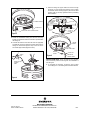
1
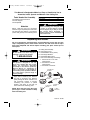
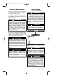
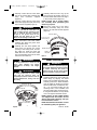
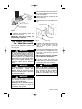
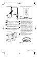
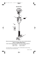
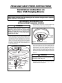
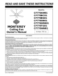
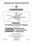
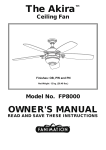
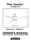
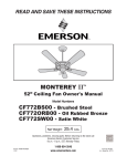
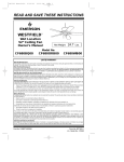
BP7386, CF3400 Corsair
11/25/09
6:20 AM
Page 1
READ AND SAVE THESE INSTRUCTIONS
CORSAIR™
44” or 52” Ceiling Fan
Owner's Manual
Model Numbers
CF3400AP
CF3400ORH
Antique Pewter
Oil Rubbed Bronze
with Highlights
Net Weight:
Part No. F40BP73860000
24” - 21.4
36” - 22.9
48” - 24.5
Lbs.
Form No. BP7386
Model No.: CF3400
BP7386, CF3400 Corsair
11/25/09
6:20 AM
!
Page 2
WARNING
WARNING: To avoid fire, shock, and serious personal injury, follow these
instructions.
Safety Instructions
1. Read your owner’s manual carefully and keep it for future reference.
2. Before servicing or cleaning unit, switch power off at service panel and lock service
panel disconnecting means to prevent power from being switched on accidentally.
When the service disconnecting means cannot be locked, securely fasten a
warning device, such as a tag, to the service panel.
3. Be careful of the fan and blades when cleaning, painting, or working near the fan.
Always turn off the power to the ceiling fan before servicing.
4. Do not put anything into the fan blades while they are turning.
5. Do not operate reversing switch until fan blades have come to a complete stop.
Additional Safety Instructions for Installation
1. To avoid possible shock, be sure electricity is turned off at the fuse box before
wiring, and do not operate fan without blades.
2. The installation is to be in accordance with the National Electrical Code, ANSI/NFPA
70-2008 and Local Codes. Use the National Electrical Code if Local Codes do not
exist. The ceiling fan must be grounded as a precaution against possible electrical
shock. Electrical installation should be made or approved by a licensed electrician.
3. The outlet box and joist must be securely mounted and capable of reliably
supporting at least 50 pounds. Use only U.L. outlet boxes listed as “Acceptable for
Fan Support”, and use the mounting screws provided with the outlet box. Most
outlet boxes commonly used for support of light fixtures are not
acceptable for fan support and may need to be replaced. Consult a qualified
electrician if in doubt.
4. The fan must be mounted with the fan blades at least 7 feet from the floor to prevent
accidental contact with the fan blades.
5. Follow the recommended instructions for the proper method of wiring your ceiling
fan. If you do not know enough about electrical wiring, have your fan installed by a
licensed electrician.
NOTE: This fan is suitable for use with solid-state speed controls.
WARNING: To reduce the risk of fire or electric shock, this fan should only be used
with fan speed control UC9020 (SW46), manufactured by Rhine Electric Co, Ltd.
WARNING: This product is designed to use only those parts supplied with this
product and/or any accessories designated specifically for use with this product by
Emerson Electric Co. Substitution of parts or accessories not designated for use with
this product by Emerson Electric Co. could result in personal injury or
property damage.
WARNING: To reduce the risk of personal injury, do not bend the blade flange when
installing the blade flanges, balancing the blades or cleaning the fan. Do not insert
foreign objects in between rotating fan blades.
DATE CODE:
The date code of this fan may be found on the box, stamped in ink on a white label.
You should record this data above and keep it in a safe place for future use.
2
Model No.: CF3400
BP7386, CF3400 Corsair
11/25/09
6:20 AM
Page 3
This Manual is Designed to Make it as Easy as Possible for You to
Assemble, Install, Operate and Maintain Your Ceiling Fan
Tools Needed for Assembly
Installed Wire Length
Wire Size A.W.G.
Up to 50 ft.
50-100 ft.
One Phillips head screwdriver
One wire stripper
One stepladder
!
Materials
14
12
WARNING
Before assembling your ceiling fan, refer
to section on proper method of wiring
your fan (Page 5). If you feel you do not
have enough wiring knowledge or
experience, have your fan installed by a
licensed electrician.
Wiring, outlet box and box connectors
must be of type required by the local code.
The minimum wire shall be a 3-conductor
(2-wire with ground) of the following sizes:
Unpacking Instructions
For your convenience, check-off boxes are provided next to each step. As each
step is completed, place a check mark in the box. This will insure that all steps
have been completed and will be helpful in finding your place should you be
interrupted.
!
A.
B.
C.
D.
E.
F.
WARNING
Do not install or use fan if any part is
damaged or missing. Call Toll-Free:
1-800-654-3545
!
WARNING
This product is designed to use only
those parts supplied with this product
and/or any accessories designated
specifically for use with this product by
Emerson Electric Co. Substitution of
parts or accessories not designated for
use with this product by Emerson Electric
Co. could result in personal injury or
property damage.
Ceiling Fan Assembly
One Ceiling Cover
One Medallion Set (2 pieces)
One Hanger Bracket
One SW46 Wall Control
One Loose Parts Bag Containing:
1. Seven #10-32 x .75” Oval
Head Screws
2. Four #8-32 x .25 Flat
Head Screws
3. Four Wire Connectors
A. CEILING FAN
ASSEMBLY
1. Open carton containing fan. Remove
top half of styrofoam unit. Remove
parts, placing all carton contents on a
soft protective surface to prevent
scratching the painted or plated
finishes, and check to see that you
have received the following parts:
B. CEILING
COVER
E. SW46 WALL
CONTROL
NOTE: Place the parts from the loose
parts bags in a small container to keep
them from being lost.
4
3
2
1
0
3
C. MEDALLION
SET (2)
D. HANGER
BRACKET
F. LOOSE
PARTS BAG
Model No.: CF3400
BP7386, CF3400 Corsair
11/25/09
6:20 AM
Page 4
Electrical Requirements
How to Hang
Your Ceiling Fan
Your new ceiling fan will require a
grounded electrical supply line of 120 volts
AC, 60 Hz, 15 amp circuit.
!
The outlet box must be securely anchored
and capable of withstanding a load of at
least 50 pounds.
!
WARNING
Turning off wall switch is not sufficient.
To avoid possible electrical shock, be
sure electricity is turned off at the main
fuse or circuit breaker box before wiring.
All wiring must be in accordance with
National and Local codes and the ceiling
fan must be properly grounded as a
precaution against possible electrical
shock.
WARNING
To reduce the risk of fire, electric shock,
or personal injury, mount fan to outlet box
marked “Acceptable for Fan Support”,
and use screws supplied with outlet box.
Most outlet boxes commonly used for
support of light fixtures are not
acceptable for fan support and may need
to be replaced. Consult a qualified
electrician if in doubt.
!
WARNING
The fan must be hung with at least 7' of
clearance from floor to blades (Figure 1).
CEILING
If your fan is to replace an existing ceiling
light fixture, turn electricity off at the main
fuse or circuit breaker box at this time and
remove the existing light fixture.
!
AT
LEAST
7'
WARNING
Turning off wall switch is not sufficient.
To avoid possible electrical shock, be
sure electricity is turned off at the main
fuse or circuit breaker box before wiring.
All wiring must be in accordance with
National and Local codes and the ceiling
fan must be properly grounded as a
precaution against possible electrical
shock.
FLOOR
Figure 1
!
!
WARNING
WARNING
The outlet box and joist must be securely
mounted and capable of supporting at
least 50 lbs. Use only a U.L. outlet box
listed as “Acceptable for Fan Support”.
To avoid possible fire or shock, follow all
wiring instructions carefully. Any
Electrical work not described in these
instructions should be done or approved
by a licensed electrician.
!
WARNING
To reduce the risk of fire, electric shock,
or personal injury, mount fan to outlet box
marked “Acceptable for Fan Support”,
and use screws supplied with outlet box.
Most outlet boxes commonly used for
support of light fixtures are not
acceptable for fan support and may need
to be replaced. Consult a qualified
electrician if in doubt.
4
Model No.: CF3400
BP7386, CF3400 Corsair
11/25/09
6:20 AM
If you feel that you do not have enough
electrical wiring knowledge or experience, have your fan installed by a
licensed electrician.
Page 5
!
WARNING
Failure to seat tab in groove could cause
damage to electrical wires and possible
shock or fire hazard.
1. Pull the electrical supply wires through
the center opening of the ceiling cover.
!
WARNING
To avoid possible fire or shock, do not
pinch wires between the hanger
ball/downrod assembly and hanger
bracket.
CEILING
COVER
How to Wire
Your Ceiling Fan
HANGER BRACKET
TAB
NOTE: Pivot the fan on its mounting
ball to improve access to the top of the
motor when making electrical connections with supply wires (Figure 3).
MOUNTING SCREW (2)
Figure 2
2. Install the ceiling cover and hanger
bracket together onto the outlet box
using the two screws supplied with the
outlet box. The hanger bracket will nest
into the ceiling cover between the
raised guides on the bottom surface of
the cover. The center hole of the ceiling
cover provides visual access to view
installation of the outlet box screws into
the threaded mounting holes of the box
(Figure 2).
!
1. Connect the green grounding lead from
the hanger ball and the green
grounding lead from the hanger bracket
to the grounding conductor of supply
(this may be a bare wire or wire with
green colored insulation) with wire
connector supplied. (Figure 3.)
!
WARNING
This product is designed to use only
those parts supplied with this product
and/or any accessories designated
specifically for use with this product by
Emerson Electric Co. Substitution of
parts or accessories not designated for
use with this product by Emerson Electric
Co. could result in personal injury or
property damage.
WARNING
To avoid possible fire or shock, do not
pinch electrical wires between the ceiling
cover and hanger bracket, or the
electrical box and the ceiling cover.
3. Pull the electrical supply wires through
the opening on the back side of the
hanger bracket for installation of the
fan’s hanger ball.
4. To prevent scratching the fan assembly,
secure the upper motor cover onto a
blade flange with masking tape.
5. Carefully lift the fan assembly and
install the fan’s hanger ball into the
hanger bracket. For added clearance,
position the fan’s reverse switch to the
side of the hanger bracket during
installation.
6. Carefully rotate the fan assembly to
engage the hanger ball groove onto the
hanger bracket locking tab. When
locked in position, the fan will not rotate
on the hanger bracket.
GREEN GROUNDING LEAD FROM
THE HANGER BRACKET
HANGER BRACKET
HANGER BALL
GREEN GROUNDING
LEAD FROM THE
HANGER BALL
Figure 3
5
Model No.: CF3400
BP7386, CF3400 Corsair
11/25/09
6:20 AM
2. Securely connect the fan motor white
wire to the supply white (neutral) wire
using
wire
connector
supplied
(Figure 4).
3. Securely connect the fan motor black
wire to the supply black (hot) wire using
wire connector supplied (Figure 4).
!
6. Carefully slide the motor ring up the
motor housing and position the ring so
that the reverse switch slot in the ring is
in the correct position (Figure 5).
NOTE: Careful not to scratch ceiling
fan assembly while positioning the
motor ring in place.
7. Secure the motor ring to the motor
housing assembly using the three
#8-32 x .25” flat head screws supplied
(Figure 5).
WARNING
Check to see that all connections are
tight, including ground, and that no bare
wire is visible at the wire connectors,
except for the ground wire. Do not
operate fan until blades are in place.
Noise and fan damage could result.
REVERSE SWITCH
#8-32 X .25" FLAT
HEAD SCREW (3)
4. After connections have been made,
separate the white and green wires
from the black wires.
5. Carefully turn the wires upward and
insert them up through the center
opening of the ceiling cover and into
the outlet box. Push the green and
white wires into one side of the outlet
box; push the black wires into the other
side of the the outlet box.
!
MOTOR RING
MOTOR
HOUSING
Figure 5
Blade Installation
WARNING
To avoid possible fire or shock, do not
pinch wires between the hanger
ball/downrod assembly and hanger
bracket.
!
!
WARNING
To reduce the risk of personal injury, do
not bend the blade flange when installing
the blades, balancing the blades or
cleaning the fan. Do not insert foreign
objects in between rotating fan blades.
WARNING
To avoid possible fire or shock, make
sure that the electrical wires are
completely inside the outlet box and not
pinched between the ceiling cover and
the ceiling.
1. With the fan suspended on the ceiling,
position a blade on top of the ceiling fan
blade flange by aligning the raised
bosses into the blade mounting holes.
Carefully position the blade medallion
onto the blade by aligning its bosses
with the blade holes. Install three #1032 x .75” oval head screws into the
mounting holes of the medallion and
securely tighten each screw (Figure 6).
If using wooden blades, be very careful
not to over tighten the blade screws.
NOTE: Screws for the wooden blades
are shipped with the blades. Do not
discard the blade packaging until you
have located the screws.
NOTE: Recommend the blades screws
be checked regularly for tightness.
SUPPLY GROUND
BLACK
WIRES
WHITE WIRES
Figure 4
Page 6
6
Model No.: CF3400
BP7386, CF3400 Corsair
11/25/09
6:20 AM
Page 7
1. Remove the wall plate and screws from
the existing wall switch. Pull switch out
from wall outlet box.
BLADE
MEDALLION
#10-32 x .75"
OVAL HEAD
SCREW
(3 per blade
assembly)
2. Disconnect wire from existing fan wall
switch (Figure 7).
3. Slide the fan control to the OFF position
(0).
BLADE
(Sold Separately)
WALL OUTLET BOX
MEDALLION BOSS
(3 per medallion)
Figure 6
2. Assemble the remaining blade per
previous instructions.
NOTE: Take care not to scratch fan
blades during installation.
SWITCH
4. Connect one BLACK wire from the fan
control to the fan/motor load wire
with a wire connector (provided)
(Figure 8).
This control is designed to operate only
one ceiling fan.
!
5. Connect the other BLACK wire from the
Fan Control to the 120VAC hot supply
wire with a wire connector (provided
with control).
WARNING
Turning off wall switch is not sufficient.
To avoid possible electrical shock, be
sure electricity is turned off at the main
fuse or circuit breaker box before wiring.
All wiring must be in accordance with
National and Local codes and the ceiling
fan must be properly grounded as a
precaution against possible electrical
shock.
!
NOTE: Use wire connectors (supplied)
to secure electrical connections.
6. If present, connect the supply white
neutral wire to the branch circuit white
neutral wire with a wire connector.
!
WARNING
WARNING
Check to see that all connections are
tight, including ground, and that no bare
wire is visible at the wire connectors,
except for the ground wire. Do not
operate fan until blades are in place.
Noise and fan damage could result.
To avoid possible fire or shock, follow all
wiring instructions carefully. Any
Electrical work not described in these
instructions should be done or approved
by a licensed electrician.
!
WALL PLATE
Figure 7
How to Wire Your Ceiling
Fan - SW46 Wall Control
WARNING
To avoid possible electrical shock, be
sure electricity is turned off at the main
fuse or circuit breaker panel.
NOTE: If you are not sure if the outlet box
is grounded, contact a licensed
electrician for advise, as it must be
grounded for safe operation.
7
Model No.: CF3400
BP7386, CF3400 Corsair
TO NEUTRAL
11/25/09
6:20 AM
Page 8
Using Your Ceiling Fan
TO FAN MOTOR LOAD
4
3
2
1
0
BLACK
BLACK
4
3
2
1
0
Figure 10
IMPORTANT
Fan installation must be completed,
including the installation of the fan
blades, before testing of the controls.
TO 120VAC
SOURCE
HOT
Figure 8
1. Restore electrical power to the outlet
box by turning the electricity on at the
main fuse box or circuit breaker panel.
2. Check the operation of the fan by
sliding the bar of the control through the
four positions marked 1 - 4 (“0” position
is OFF) (Figure 10).
3. All fans are shipped from the factory
with the reversing switch positioned to
circulate air downward. If airflow is
desired in opposite direction, turn your
fan OFF and wait for the blades to stop
turning, then slide the reversing switch
to the opposite position, and turn fan on
again (Figure 11).
4. The fan blades will turn in the opposite
direction and reverse the airflow.
7. Attach the fan control to the wall outlet
box with two 6-32 x 3/4” screws
(provided with control).
8. Position the wall plate (provided with
control) onto the speed control. Using
the two 6-32 x 1/4” screws, fasten the
wall plate to the control (Figure 9).
9. Installation of the ceiling fan is now
complete. Restore power at the main
fuse box or circuit breaker panel.
OUTLET BOX
SW46 FAN CONTROL
4
3
2
REVERSE SWITCH
1
0
6-32 x 3/4"
SCREW (2)
WALL PLATE
6-32 x 1/4"
SCREW (2)
Figure 11
Figure 9
8
Model No.: CF3400
BP7386, CF3400 Corsair
11/25/09
6:20 AM
Page 9
Maintenance
Accessories
IMPORTANT CARE INSTRUCTIONS
for your Ceiling Fan
1. Blades (see store or catalog).
Periodic cleaning of your new ceiling fan is
the only maintenance that is needed.
The use of any other control not
specifically approved for this fan could
result in fire, shock and personal injury.
When cleaning, use only a soft brush or
lint free cloth to avoid scratching the finish.
Abrasive cleaning agents are not required
and should be avoided to prevent damage
to finish.
!
WARNING
!
WARNING
!
This product is designed to use only
those parts supplied with this product
and/or any accessories designated
specifically for use with this product by
Emerson Electric Co. Substitution of
parts or accessories not designated for
use with this product by Emerson Electric
Co. could result in personal injury or
property damage.
WARNING
Do not use water when cleaning your
ceiling fan. It could damage the motor or
the blades and create the possibility of an
electrical shock.
WARNING: FOR YOUR OWN SAFETY TURN OFF POWER AT FUSE BOX
!
OR CIRCUIT BREAKER BEFORE TROUBLE SHOOTING YOUR FAN.
Trouble Shooting
TROUBLE
1. Fan will not
start.
PROBABLE CAUSE
1. Fuse or circuit breaker
blown.
2. Loose electrical connections
to the fan or wall control.
3. Fan Wall Control is OFF.
SUGGESTED REMEDY
1. Check main and branch
circuit fuses or circuit breakers.
! WARNING: Make sure
main power is turned off.
2. Check that all electrical
connections are secure.
3. Turn ON Fan Wall Control.
WARNING: Make sure main
power is turned off.
1. Attach blades to fan before
operating or tightening the blade
screws.
!
2. Fan sounds
noisy.
1. Blades not securely attached
to fan.
3. Fan wobbles
excessively.
1. Fan blades are not seated
into the blade flanges properly.
2. Fan blades are out of balance.
9
1. Check to be sure that the
flange and medallion bosses are
seated into the blade mounting
holes.
2. Follow the instructions of the
blade balancing kit supplied
with the ceiling fan to correct
the wobble.
Model No.: CF3400
BP7386, CF3400 Corsair
11/25/09
6:20 AM
Page 10
Repair Parts Listing
Part Numbers
Key
No.
Description
Model No.
Model No.
CF3400AP00
CF3400ORH00
763816-AP
763816-ORH
1
Ceiling Plate (1)
2
Hanger Bracket Assembly (1)
760732
760732
3
Hangerball Assembly (1)
763949
763949
4
Reverse Switch (1)
763898
763898
5
Axillary Capacitor 8.0 uF (1)
763948
763948
6
Motor Assembly, K55XL (1)
763820
763820
7
Medallions (set of two)
763897-AP
763897-ORH
8
Finial Cover (1)
763838-AP
763838-ORH
9
SW46 Wall Control (1)
761971
761971
*
Parts Bag, Containing:
763828
763828
10
Connectors, Wire, 12 Ga. (4)
—
—
11
#10-32 x .75” Oval Head Screws (7)
—
—
12
#8-32 x .25” Flat Head Screws (4)
—
—
—
Owner's Manual (1)
BP7386
BP7386
10
Model No.: CF3400
BP7386, CF3400 Corsair
11/25/09
6:20 AM
Page 11
Repair Parts
1
2
3
4
12
5
6
10
9
4
3
2
1
0
7
11
8
Before discarding packaging material, be certain all parts have been removed.
HOW TO ORDER REPAIR PARTS
WHEN ORDERING REPAIR PARTS, ALWAYS GIVE THE FOLLOWING INFORMATION:
• PART NUMBER
• NAME OF ITEM
• PART DESCRIPTION
• MODEL NUMBER
The model number of your Fan will be found on a label attached to the top housing.
For repair parts, phone 1-800-654-3545.
11
Model No.: CF3400
BP7386, CF3400 Corsair
11/25/09
6:20 AM
Page 12
LIMITED WARRANTY
What The Warranty Covers:
This warranty covers the motor and the other components and accessories of your Emerson ceiling fan against all defects in
workmanship and materials. You must be the original purchaser or user of the product to be covered.
What The Period Of Coverage Is:
As it applies to the motor, this warranty will last for the lifetime of your ceiling fan. All other components and accessories are
covered by this warranty for one year from the date you purchased your ceiling fan. ANY IMPLIED WARRANTY OF
MERCHANTABILITY OR FITNESS FOR A PARTICULAR PURPOSE, MADE WITH RESPECT TO COMPONENTS AND
ACCESSORIES IS ALSO LIMITED TO ONE YEAR.
What Will Emerson Electric Co. Do To Correct Problems:
Emerson Electric Co. will replace a defective Emerson Air Comfort Ceiling Fan motor, blade, component or other accessory at
no charge to you. If repair of the motor or blades is not practical or possible within a reasonable time and no replacement can
be provided, Emerson will refund the actual purchase price of your fan. WE WILL SHIP THE REPAIRED PRODUCT OR
REPLACEMENT TO YOU AT NO CHARGE, BUT YOU ARE RESPONSIBLE FOR ALL COSTS OR REMOVAL, REINSTALLATION
AND SHIPPING OF THE PRODUCT TO EMERSON ELECTRIC CO.
How Can You Get Service:
YOU MUST HAVE PROOF OF YOUR PURCHASE OF THE CEILING FAN TO OBTAIN LIMITED WARRANTY SERVICE. KEEP YOUR
RECEIPT OR OTHER PROOF OF PURCHASE. You can return the product to our factory or to your nearest authorized service
center.
• To return the product to the factory, obtain a return authorization and service identification tag by writing to Air Comfort
Products, Division of Emerson Electric Electric Co., 8100 W. Florissant Ave., St. Louis, MO 63136. Include all model
numbers shown on the product with your request.
• To return the product to an authorized service center, call 1-800-654-3545 for the address of the nearest authorized service
center.
You will be responsible for all insurance, freight or other transportation charges to our factory or authorized service center. Your
Emerson Air Comfort Ceiling Fan should be properly packed to avoid damage in transit since we will not be responsible for any
such damage.
What Is Not Covered:
The glass globes and light bulbs of your ceiling fan are not covered by this warranty. This warranty also does not cover any
defects, malfunctions or failures caused by:
• Repairs by persons not authorized by Emerson Electric Co.,
• Use of parts or accessories not authorized by Emerson Electric Co.,
• Mishandling, improper installation, modifications or damage to your ceiling fan while in your possession, or
• Unreasonable use, misuse, abuse, including failing to do reasonable and necessary maintenance, and normal wear and tear.
Additionally, this warranty and any implied warranty of merchantability or fitness for a particular purpose are voided when:
• The original purchaser or user ceases to own the product, or
• The fan is moved from its original point of installation.
This warranty is only valid within the 50 states of the United States and the District of Columbia. No other written or oral
warranties apply, and no employee, agent, dealer or other person is authorized to give any warranties on behalf of Emerson
Electric Co.
REPAIR, REPLACEMENT OR A REFUND ARE THE EXCLUSIVE REMEDIES AVAILABLE UNDER THIS WARRANTY AND
EMERSON IS NOT RESPONSIBLE FOR DAMAGES OF ANY KIND, INCLUDING INCIDENTAL AND CONSEQUENTIAL DAMAGES.
Incidental damages include but are not limited to such damages as loss of time and loss of use. Consequential damages include
but are not limited to the cost of repairing or replacing other property which was damaged if this product does not work
properly.
How State Law Relates To The Warranty:
Some states do not allow the exclusion or limitation of incidental or consequential damages so the above exclusion or limitation
may not apply to you. This warranty gives you specific legal rights, and you may also have other rights which vary from state
to state.
Air Comfort Products
DIVISION OF EMERSON ELECTRIC CO.
8100 W. Florissant • St. Louis, MO 63136
Part No. F40BP73860000
Printed in China 11/09
Form No. BP7386
Model No.: CF3400
READ AND SAVE THESE INSTRUCTIONS
Installation Instruction on
New CSA Hanging Device
INSTALLATION INSTRUCTIONS
Always properly install the ceiling fan mounting plate to a structural ceiling joist that is capable of
reliably supporting at least 50 pounds.
PRELIMINARY PROCEDURES FOR
EXTRA SUPPORT HANGING SYSTEM
!
2. Pull the electrical supply wires and support cable through
the center opening of the ceiling cover (Figure 2).
WARNING
Turning off wall switch is not sufficient.
To avoid possible electrical shock, be sure
electricity is turned off at the main fuse box before
wiring. All wiring must be in accordance with
National and Local codes and the ceiling fan must
be properly grounded as a precaution against
possible electrical shock.
1. Slip the loop of the short steel support cable onto the flat
washer, lockwasher and 2” lag screw (supplied). Attach
the short steel support cable through the center hole of
the outlet box into the supporting joist by securely
tightening the flat washer, lockwasher and 2” lag screw
(Figure 1). The support cable lag screw must be installed
such that it is structurally independent of the outlet box.
Pre-drill the support joist with a 9/64” diameter drill to
prevent splitting the joist.
OUTLET BOX
ELECTRIC
DRYWALL CEILING
FLAT WASHER,
LOCKWASHER, &
2" LAG SCREW
SHORT STEEL
SUPPORT CABLE
CEILING
COVER
HANGER BRACKET
TAB
Figure 2
MOUNTING SCREW (2)
3. Install the ceiling cover and hanger bracket together onto
the outlet box using the two screws supplied with the
ceiling fan. Discard the screws that were supplied with
the electrical box. The hanger bracket will nest into the
ceiling cover between the raised guides on the bottom
surface of the cover. The center hole of the ceiling cover
provides visual access to view installation of the outlet
box screws into the threaded mounting holes of the box
(Figure 3).
!
OUTLET BOX
CENTER HOLE
4. Pull the electrical supply wires and support cable through
the opening on the back side of the hanger bracket for
installation of the fan’s hanger ball.
LOOP
FLAT WASHER
LOCKWASHER
2" LAG SCREW
Figure 1
WARNING
To avoid possible fire or shock, do not pinch electrical
wires between the ceiling cover and hanger bracket, or the
electrical box and the ceiling cover.
JOIST
SHORT STEEL
SUPPORT CABLE
7. Insert the ceiling fan support cable from the fan through
the brass nut and reinstall the machine screw. Tighten
the machine screw securely (Figure 5). Be sure the steel
support cable is securely tightened before proceeding
with installation.
HANGER BRACKET
ELECTRIC SUPPLY
WIRES OMMITED
FOR CLARITY
OUTLET BOX
DRYWALL CEILING
SHORT STEEL
SUPPORT CABLE
HANGER BALL
SHORT STEEL UPPER SUPPORT CABLE
CEILING
COVER
CEILING FAN
SUPPORT CABLE
Figure 3
5. Install the assembled ceiling fan onto the mounting
bracket in accordance with the instructions provided with
the ceiling fan.
6. Unscrew the machine screw from the brass nut (supplied)
and feed the end of the ceiling fan support cable from the
ceiling fan downrod through the loop on the end of the
short steel support cable (Figures 4 and 5).
CEILING
COVER
SHORT STEEL
SUPPORT CABLE LOOP
MACHINE SCREW
BRASS
NUT
CEILING FAN
SUPPORT
CABLE
MACHINE
SCREW
Figure 5
BRASS NUT
CEILING FAN
SUPPORT CABLE
INSTALLATION NOTE: Check all fasteners and retighten
where necessary before continuing with the installation of
the ceiling fan.
8. To complete fan assembly, proceed to “How to Wire
Your Ceiling Fan” in the Ceiling Fan Instructions Manual.
Figure 4
Air Comfort Products
Form No. BP7410
Part No. F40BP74100000
DIVISION OF EMERSON ELECTRIC CO.
8100 W. Florissant • St. Louis, MO 63136
10/09