1
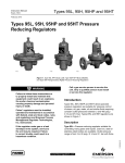
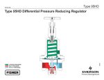
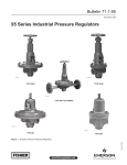
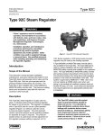
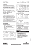
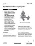
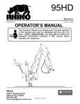
Types 95LD and 95HD
Instruction Manual
Form 1396
November 2009
Types 95LD and 95HD Differential
Pressure Regulators
W1894-1
W6195
W1894-1
TYPE 95LD (FLANGED)
TYPE 95LD
TYPE 95HD
Figure 1. 95 Series Differential Pressure Regulators
Warning
Failure to follow these instructions or
to properly install and maintain this
equipment could result in an explosion,
fire and/or chemical contamination
causing property damage and personal
injury or death.
Fisher® regulators must be installed,
operated, and maintained in accordance
with federal, state, and local codes,
rules and regulations, and Emerson
Process Management Regulator
Technologies Inc. instructions.
If the regulator vents gas or a leak
develops in the system, service to
the unit may be required. Failure
to correct trouble could result in a
hazardous condition.
Installation, operation, and maintenance
procedures performed by unqualified
personnel may result in improper
adjustment and unsafe operation. Either
condition may result in equipment
damage or personal injury. Use qualified
personnel when installing, operating,
and maintaining the Types 95LD
and 95HD regulators.
Introduction
Scope of the Manual
This manual provides instructions for the installation,
adjustment, maintenance, and parts ordering for
95 Series differential pressure regulators. These
regulators usually are shipped separately for line
or panel mounting or installed on other equipment.
Instructions and parts lists for other equipment are
found in separate manuals.
www.fisherregulators.com
D100257X012
!
Types 95LD and 95HD
Specifications
Available Configurations
Type 95LD: Low-pressure differential regulator for
2 to 30 psi (0,14 to 2,1 bar) differential pressures
Type 95HD: High-pressure differential regulator for
5 to 150 psi (0,34 to 10,3 bar) differential pressures
Body and Orifice Sizes
Types 95LD, 95HD
NPS 1/4:
1/4-inch (6,4 mm) orifice
NPS 1/2 (DN 15):
3/8-inch (9,5 mm) orifice
NPS 3/4 and 1 (DN 20 and 25):
9/16-inch (14 mm) orifice
Type 95HD
NPS 1-1/2 and 2 (DN 40 and 50):
1-1/16-inch (27 mm) orifice
End Connection Styles
NPT, ASME flanged 14-inch face-to-face
EN flanged; 356 mm face-to-face, CL150 RF,
CL300 RF or SWE
Maximum Cold Working Pressures of Body Size
and Materials
See Table 1
Differential Pressure Ranges
See Table 2
Shutoff Classification Per ANSI/FCI 70-3-2004
Metal Seats: Class IV
Elastomer Seats: Class VI or better
Polytetrafluoroethylene (PTFE): Class IV
Flow and Sizing Coefficients
See Table 3
Maximum Temperature Ranges of Diaphragm and
Seat Materials(1)(2)
Material
Nitrile (NBR)
Neoprene (CR)
Fluorocarbon (FKM)(3)
Ethylenepropylene (EPDM)
PTFE
Stainless Steel (SST)
Temperature RANGE
-40° to 180°F
-40° to 180°F
0° to 300°F
-40° to 275°F
-40° to 400°F
-40° to 650°F
(-40° to 82°C)
(-40° to 82°C)
(-18° to 149°C)
(-40° to 135°C)
(-40° to 204°C)
(-40° to 343°C)
Maximum Temperature Ranges of Body Materials(1)(2)
TYPE
Body and spring
case materials
Temperature RANGE
95LD,
95HD
Cast Iron
Steel
Stainless Steel
-40° to 406°F (-40° to 208°C)
-20° to 450°F (-29° to 232°C)
-40° to 450°F (-40° to 232°C)
Pressure Setting Adjustment
Handwheel
Pressure Registration
Internal with outside pressure source for
differential pressure or pressure loading
Approximate Weights
Type 95HD
NPS 1/4 body: 4 pounds (2 kg)
NPS 1/2 (DN 15) body:
8 pounds (4 kg)
NPS 3/4 and 1 (DN 20 and 25) bodies:
20 pounds (9 kg)
NPS 1-1/2 and 2 (DN 40 and 50) bodies:
73 pounds (33 kg)
Type 95LD
NPS 1/4 (DN 6) body:
6 pounds (3 kg)
NPS 1/2 (DN 15) body:
12 pounds (5 kg)
NPS 3/4 and 1 (DN 20 and 25) bodies:
32 pounds (15 kg)
1. The pressure/temperature limits in this Instruction Manual, and any applicable standard or code limitation should not be exceeded.
2. Pressures and/or the body end connection may decrease these maximum temperatures.
3. Fluorocarbon (FKM) is limited to 200°F (93°C) hot water.
Product Description
Types 95LD and 95HD are small-size, largecapacity, differential pressure regulators. They are
suitable for steam, air, gas, oil, water, and other fluids
control. Typical applications include use on testing
fixtures, wash tanks, sterilizers, steam tables,
fuel lines, and plant air supplies. The differential
pressure range of the Type 95LD regulator is from
2
2 to 30 psi (0,14 to 2,1 bar) (three spring ranges). The
Type 95HD differential pressure range is from
5 to 150 psi (0,34 to 10,3 bar) (seven spring ranges).
Specifications
The Specifications section gives some general
specifications for the 95 Series differential pressure
regulators. The nameplates give detailed information
for a particular regulator as it comes from the factory.
Types 95LD and 95HD
Table 1. Maximum Cold Working Pressures of Body Size and Materials
type
maximum inlet pressure
maximum outlet pressure(1)
body and spring
case materials
diaphragm and
seat materials
Psig
bar
Psig
bar
Cast iron
Elastomer
All-Metal
250
250
17,2
17,2
50
50
3,4
3,4
Steel or
Stainless Steel
Elastomer
All-Metal
300
300
20,7
20,7
125
125
8,6
8,6
Cast iron
Elastomer
All-Metal
250
250
17,2
17,2
250
250
17,2
17,2
Steel or
Stainless Steel
Elastomer
All-Metal
300
300
20,7
20,7
300
300
20,7
20,7
95LD
95HD
1. The maximum outlet pressure equals the spring case loading pressure plus the maximum spring setting.
Table 2. Spring Part Numbers for 95 Series Body Sizes and Pressure Ranges
TYPE
95LD
95HD
differential pressure
range(1)
Psig
bar
Spring Wire
Diameter
Inches (mm)
1/4
2 to 6
5 to 15
13 to 30
0,14 to 0,41
0,34 to 1,0
0,90 to 2,1
0.148 (3,76)
0.172 (4,37)
0.207 (5,26)
2.00 (50,8)
2.00 (50,8)
1.94 (49,2)
1E392527022
1E392627012
1E392727142
Yellow
Green
Red
1/2 (15)
2 to 6
5 to 15
13 to 30
0,14 to 0,41
0,34 to 1,0
0,90 to 2,1
0.207 (5,26)
0.234 (5,94)
0.281 (7,14)
2.50 (63,5)
2.57 (65,2)
2.44 (62,0)
1E395627022
1D7455T0012
1E395727192
Yellow
Green
Red
3/4, 1
(20, 25)
2 to 6
5 to 15
13 to 30
0,14 to 0,41
0,34 to 1,0
0,90 to 2,1
0.306 (7,77)
0.343 (8,71)
0.406 (10,3)
4.00 (102)
4.00 (102)
4.00 (102)
1E398927022
1E399027142
1E399127162
Yellow
Green
Red
1/4
15 to 30
25 to 75
70 to 150
1,0 to 2,1
1,7 to 5,2
4,8 to 10,3
0.148 (3,76)
0.172 (4,37)
0.207 (5,26)
2.00 (50,8)
2.00 (50,8)
1.94 (49,2)
1E392527022
1E392627012
1E392727142
Yellow
Green
Red
1/2 (15)
15 to 30
25 to 75
70 to 150
1,0 to 2,1
1,7 to 5,2
4,8 to 10,3
0.148 (3,76)
0.172 (4,37)
0.207 (5,26)
2.50 (63,5)
2.57 (65,2)
2.44 (62,0)
1E395627022
1D7455T0012
1E395727192
Yellow
Green
Red
3/4, 1
(20, 25)
15 to 30
25 to 75
70 to 150
1,0 to 2,1
1,7 to 5,2
4,8 to 10,3
0.306 (7,77)
0.343 (8,71)
0.406 (10,3)
4.00 (102)
4.00 (102)
4.00 (102)
1E398927022
1E399027142
1E399127162
Yellow
Green
Red
1-1/2, 2
(40, 50)
5 to 80
60 to 120
100 to 140
120 to 150
0,34 to 5,5
4,1 to 8,3
6,9 to 9,7
8,3 to 10,3
0.531
0.562
0.593
0.656
6.56
6.56
6.50
6.57
1E795327082
1E795427082
1E793327082
1P788827082
Light Blue
Light Gray
Yellow
Black
body size,
NPS (DN)
(13,5)
(14,3)
(15,1)
(16,7)
Spring free
length
Inches (mm)
spring part
number
color
(167)
(167)
(165)
(167)
1. For Types 95LD and 95HD regulators, the pressure ranges indicate the differential pressure that can be obtained with the indicated spring. The differential pressure (spring setting) is
added to the spring case loading pressure to determine the actual outlet pressure.
Table 3. Types 95LD and HD Flow and Sizing Coefficients
body size,
NPS (DN)
WIDE-OPEN COEFFICIENTS (FOR RELIEF SIZING)
Cv
Cg
Cs
1/4
0.8
28
1.40
1/2 (15)
1.9
67
3.35
3/4, 1 (20, 25)
4.4
156
7.80
1-1/2, 2
(40, 50)
12.5
475
23.75
C1
Km
IEC SIZING COEFFICIENTS
XT
0.83
35
0.71
0.775
0.67
38
0.83
0.913
FD
FL
0.58
0.91
0.58
0.84
0.44
0.82
0.37
0.91
Km = FL2
3
Type 95HD
October 2006
TypeReducing
95HD
Types
95LDDifferential
and 95HD Pressure
Type 95HD
Regulator
95HD Differential Pressure Reducing Regulator
Handwheel
Installation
PITOT TUBE
diaphragm
PRESSURE A*
(SPRING CASE
LOADING
PRESSURE)
PRESSURE A +
SPRING SETTING =
PRESSURE B
valve
stem
PRESSURE B
(OUTLET
PRESSURE)
ORIFICE
W0078*
loading
LOADINGpressure
PRESSURE
inlet
INLETpressure
PRESSURE
outlet
OUTLETpressure
PRESSURE
*PRESSURE A MAY BE ANOTHER PRESSURE SYSTEM
OR A MANUAL LOADING REGULATOR
valve plug
valve plug
spring
Figure 2. Type 95HD Operational Schematic
(Also Typical of 95LD)
Principle of Operation
Types 95LD and 95HD regulators maintain a differential
pressure between the loading supply pressure and the
downstream pressure of the regulator.
Refer to Figure 2. The design of the regulator isolates
the diaphragm and pressure response chamber from
the main flow stream. The downstream pressure
(outlet pressure) is registered under the diaphragm
through the pitot tube or registration hole. If the
downstream pressure increases, pressure under the
diaphragm also increases. This force overcomes
the spring compression and loading supply pressure,
allowing the stem to rise. The valve plug spring forces
the valve plug closer to the orifice. Flow through the
regulator is reduced so that downstream pressure
returns to the desired differential level. When the
downstream pressure decreases, the opposite
action takes place. Pressure under the diaphragm
decreases. The valve stem pushes the valve plug
downward, opening the flow stream and increasing the
flow through the regulator. Downstream pressure rises
back to the desired differential level.
4
Unpack the regulator and remove the protective
shipping plugs from the end connections of the
body and the pressure connection in the spring
case. Be sure the body and connecting pipelines
are clean. Coat the pipeline threads with a suitable
pipe compound. The regulator may be installed in
any position as long as the flow is in the direction
indicated by the arrow cast on the body.
The design of the regulator isolates the diaphragm
and the pressure response chamber from the main
flow steam. Outlet pressure registers under the
diaphragm through the pitot tube or registration
hole. Loading pressure registers on the top of the
diaphragm. The loading pressure is connected to the
NPT connection in the spring case.
Overpressure Protection
!
Warning
Personal injury or system damage
may result if this regulator is installed,
without appropriate overpressure
protection, where service conditions
could exceed the limits given in the
Specification section and/or regulator
nameplate. Regulator installations
should be adequately protected from
physical damage.
The Types 95LD and 95HD have outlet pressure
ratings that are lower than the inlet pressure ratings.
Some type of overpressure protection is needed
if the actual inlet pressure can exceed the outlet
pressure rating. Common methods of overpressure
protection include relief valves, monitoring
regulators, or series regulation.
The maximum pressures that should not be exceeded
are stamped on the nameplate and are also shown in
the Specifications section and Table 1.
M1006
control
spring
M1006
NG PRESSURE
PRESSURE
ET PRESSURE
Before installing the regulator, be sure the chosen
location is adequately protected from damage by
vehicles and other external sources. The regulator
should be away from building eaves and above
probable snow levels. Temperature conditions should
not exceed the limits shown in Specifications section.
Types 95LD and 95HD
plant air
atmosphere
block
valve
Type 67CFR Regulator
(inlet) vent
(outlet) vent
type 95ld regulator
(also typical of 95hd)
Figure 3. Installation Schematic
Startup
Adjustment
Note
The Specifications section and
Table 1 show the maximum inlet and
the differential pressures for specific
constructions. Use pressure gauges
to monitor inlet pressure, outlet
pressure, and any intermediate pressure
during startup.
1. Check that proper installation is completed
and downstream equipment has been
properly adjusted.
2. Make sure all block and vent valves are closed.
3. Back out the adjusting screw by turning
the handwheel counterclockwise continuously.
4. Slowly open the valves in the following order:
a. Loading supply and control line valve(s), if used
b. Inlet block valve
c. Outlet block valve
5. Set the regulator to the desired outlet (control)
pressure according to the Adjustment procedure.
Key numbers are referenced in Figures 4 and 5.
The factory setting of the regulator can be varied
within the pressure range stamped on the nameplate.
To change the outlet pressure, turn the handwheel
(key 38) clockwise to increase outlet pressure, or
counterclockwise to decrease it. Monitor the outlet
pressure with a test gauge during the adjustment.
All regulator springs can be backed off to provide
zero outlet. Recommended outlet pressure ranges
available, maximum inlet pressures and temperatures,
and color codes of the respective springs are shown in
Tables 1 and 2.
Shutdown
1. Isolate the regulator from the system.
2. Close the upstream block valve to the regulator inlet.
3. Close the downstream block valve to the
regulator outlet.
4. Vent the downstream pressure by slowly opening
the vent valve to vent downstream pressure.
5. Vent loading pressure slowly to release pressure
in the spring case.
6. Vent inlet pressure slowly (through the vent valve)
to release all remaining pressure in the regulator.
5
Types 95LD and 95HD
Maintenance
!
Warning
To avoid personal injury and equipment
damage, isolate the regulator from all
pressures, including loading pressure.
Cautiously release all pressure from the
regulator before attempting disassembly.
Due to normal wear and damage that may occur
from external sources, the regulator should be
inspected periodically. Parts such as the O-rings,
gaskets, diaphragm, and packing should be replaced
as necessary. The frequency of inspection and
replacement depends upon the severity of service
conditions or the requirements of state and federal laws.
Suitable lubricants are shown in the assembly
drawings. Apply the lubricants as the regulator is
being reassembled.
Refer to Figure 4 or 5 while disassembling the
regulator. The regulator does not have to be taken
out of the pipeline to be disassembled. Relieve the
spring compression by turning the handwheel
(key 38) counterclockwise.
Replacement or Maintenance of Orifice
and Valve Plug
If it appears that the valve does not shut off tightly,
the orifice and valve plug may be worn or damaged.
Proceed as follows to check them.
1. Unscrew the valve plug guide (key 5) from the
body (key 1). The valve plug spring (key 10) and
the valve plug (key 4) will normally come out of
the body along with the valve plug guide.
2. Remove the orifice (key 3). Examine the orifice
and valve plug seating surfaces for damage.
Note
If the damage to elastomer or metal
seating surfaces is severe, replace the
orifice and valve plug with new parts.
However, by following the lapping
procedure below, it is possible to repair
metal seating surfaces if they are only
slightly worn or scratched.
b. Take the valve plug or orifice and move it in a
“Figure 8” motion on the lapping compound.
Do not allow the part to tip or rock since this
would round the corners.
c. Repeat step b for each part, this time using
an 800-grit or 1000-grit silicon carbide or
aluminum oxide lapping compound.
d. Wash away all traces of the lapping compound.
To help prevent scratching the seating surfaces,
a light coat of oil may be applied before returning the valve plug and orifice to the body.
4. Return the orifice, valve plug, valve plug spring,
and valve plug guide to the body.
Replacement of Packing
Leakage around the adjusting screw may indicate
worn packing material. Follow the instructions below
to replace the packing rings.
1. Take out the machine screw (key 41) and lift off
the washer (key 44) and handwheel (key 38).
2. Unscrew the packing box (key 32). Unscrew the
packing nut (key 35) and the packing follower
(key 34) off of the adjusting screw (key 33).
3. Unscrew and pull the adjusting screw out through
the bottom of the packing box.
4. Pull out the old packing (key 36) and replace it
with three new packing rings. Replace the
packing box gasket (key 37).
5. Reassemble the stuffing box unit by returning the
adjusting screw to the inside of the packing box.
Slip the packing follower onto the adjusting
screw and into the packing box. Screw on the
packing nut.
6. Put the packing box back onto the spring case.
Set the handwheel and washer on the adjusting
screw and screw in the machine screw.
Replacement of Diaphragm
When the regulator does not respond to differential
pressure changes or the loading pressure seems to
leak to the downstream piping, the diaphragm could be
worn out or ruptured. Inspect the diaphragm as follows:
3. Lapping procedure:
1. Remove the cap screws (key 16) from the
diaphragm casing. Lift the entire spring case
(key 2) off of the body.
a. Place a small amount of 500-grit silicon carbide
or aluminum oxide lapping compound on a flat
surface such as a piece of heavy plate glass.
2. Take the upper spring seat (key 9), regulator spring
(key 11) and the lower spring seat (key 8,
Type 95HD) out of the lower spring case. In
6
Types 95LD and 95HD
44
41
38
34
33
39
43
42
metal diaphragms
(key 12)
SPRING (key 11)
35
40
GASKETS (key 19)
36
32
ns
TYPE 95LD WITH TWO METAL DIAPHRAGMS
(EXCEPT ONLY TYPE 95LD, NPS 1/4,
2 TO 6 PSI (0,14 to 0,41 bar) RANGE)
37
2
ns
21
9
11
16
metal diaphragm
(key 12)
SPRING (key 11)
12
GASKETS (key 19)
20
7
6
3
ns
1
PARTS NOT SHOWN
13, 8, 18 N.S. - NEVER-SEEZ®
4
5 10
pitot tube used in
NPS 3/4 and 1
(dn 20 AND 25)
sizes only
TYPE 95LD (nps 1/4, 2 TO 6 PSI
(0,14 to 0,41 bar) RANGE) WITH
METAL DIAPHRAGM
30A6999-A
Figure 4. Type 95LD Regulator Assembly
Type 95LD, the lower spring seat and diaphragm
plate (key 21) are threaded together and can be
removed as one unit.
3. If the unit has metal diaphragms,
a.
Find the pusher post (key 30) and place on
a surface with the larger flat surface down and
the thread stem up (metal diaphragm pusher
post has a recessed diameter in the bottom
surface). Then, find one smaller composition
gasket (key 47) and fit it over the threaded end
of the pusher post. Find and take one of the
diaphragm heads and slip it over the threaded
end of the pusher post with the chamfered
side of the diaphragm head toward the gasket.
Take a second gasket and place it over the
threaded end of the pusher post on top of the
diaphragm head.
b. Replace one of the two large diaphragm gaskets
(key 19) on the surface of the body that will
support the diaphragms. There will be two
Never-Seez® is a trademark of Bostik Corp.
diaphragms used per regulator, except for
Type 95LD, NPS 1/4 with 2 to 6 psi (0,14
to 0,41 bar) outlet setting which uses only one
metal diaphragm (the metal diaphragm is in
between two diaphragm gaskets). Another
diaphragm gasket will be placed on top of the
second metal diaphragm. The raised surfaces of
the metal diaphragms should be placed in the
unit so that they are facing toward the assembler
(toward the spring) except only when one metal
diaphragm is being used then the raised surface
should be facing down (towards the body).
See Figures 4 and 5 as references.
4. Set the diaphragm plate, lower spring seat, spring,
and upper spring seat back onto the diaphragm.
5. Place the spring case on the body. Tighten the
cap screws finger tight only.
6. To ensure proper slack in the diaphragm, apply
some spring force to the diaphragm by turning the
handwheel clockwise.
7. Finish tightening the cap screws.
7
Types 95LD and 95HD
41
44
38
33
34
39
43
42
35
32
40
32
ns
37
metal diaphragms
(key 12)
SPRING (key 11)
9
ns
11
16
2
12
8
19
20
7
3
ns
4
ns
10
30A7023-A
B0876-1
6
GASKETS (key 19)
pitot tube used
in NPS 3/4 through 2
(Dn 20 through 50)
sizes only
1
5
parts not shown 13, 18, 30, 31, 45, 54
n.s. - NEVER-SEEZ®
Figure 5. Type 95HD Regulator Assembly
Parts Ordering
Key Description
When corresponding with your local Sales Office about
this equipment, always reference the equipment serial
number or FS number that can be found on
the nameplate.
When ordering replacement parts, reference the key
number of each needed part as found in the following
parts list. Separate kits containing all recommended
spare parts are available.
Parts List
Key Description
Part Number
Parts Kit (Included are keys 3, 4, 10, 12, and 19 (for All Metal Trim only)
Type 95HD
For Brass and Neoprene (CR) (CR) Trim
NPS 1/4 body
R95HX000012
NPS 1/2 (DN 15) body
R95HX000022
NPS 3/4 and 1 (DN 20 and 25) bodies
R95HX000032
For 416 Stainless Steel and Neoprene (CR) (CR) Trim
NPS 1/4 body
R95HX000102
NPS 1/2 (DN 15) body
R95HX000112
NPS 3/4 and 1 (DN 20 and 25) bodies
R95HX000122
NPS 1-1/2 and 2 (DN 40 and 50) bodies
R95HX000042
For All Metal Trim
NPS 1/4 body
R95HX000332
NPS 1/2 (DN 15) body
R95HX000342
NPS 3/4 and 1 (DN 20 and 25) bodies
R95HX000352
NPS 1-1/2 and 2 (DN 40 and 50) bodies
R95HX000362
Extra parts for NPS 1-1/2 and 2
(DN 40 and 50) bodies include
keys 45, 47, 51 and 52
8
TYPE 95HD WITH TWO METAL DIAPHRAGMS
Part Number
Parts Kit (Included are keys 3, 4, 10, 12, and 19
(for All Metal Trim only) (continued)
Type 95LD
For Brass and Neoprene (CR) (CR) Trim
NPS 1/4 body
R95LX000012
NPS 1/2 (DN 15) body
R95LX000022
NPS 3/4 and 1 (DN 20 and 25) bodies
R95LX000032
For 416 Stainless Steel and Neoprene (CR) (CR) Trim
NPS 1/4 body
R95LX000102
NPS 1/2 (DN 15) body
R95LX000112
NPS 3/4 and 1 (DN 20 and 25) bodies
R95LX000122
For All Metal Trim
NPS 1/4 body
R95LX000252
NPS 1/2 (DN 15) body
R95LX000262
NPS 3/4 and 1 (DN 20 and 25) bodies
R95LX000272
1
Body
See following Table
2 Spring Case
Type 95HD
Steel
NPS 1/4 body
2L443222012
NPS 1/2 (DN 15) body
2L324122012
NPS 3/4 and 1 (DN 20 and 25) bodies
3E408822012
NPS 1-1/2 and 2 (DN 40 and 50) bodies
31A9804X022
Stainless Steel
NPS 1/4 body
2L443233092
NPS 1/2 (DN 15) body
2L3241X0012
NPS 3/4 and 1 (DN 20 and 25) bodies
3E4088X00A2
NPS 1-1/2 and 2 (DN 40 and 50) bodies 31A9804X042
Type 95LD
Steel
NPS 1/4 body
2L443422012
NPS 1/2 (DN 15) body
3L324222012
NPS 3/4 and 1 (DN 20 and 25) bodies
4F432322012
Types 95LD and 95HD
Key Description
2 Spring Case (continued)
Type 95LD (continued)
Stainless Steel
NPS 1/4 body
NPS 1/2 (DN 15) body
NPS 3/4 and 1 (DN 20 and 25) bodies
3* Orifice
Metal-to-metal seat
NPS 1/4 body
416 Stainless steel
316 Stainless steel
NPS 1/2 (DN 15) body
416 Stainless steel
316 Stainless steel
NPS 3/4 and 1 (DN 20 and 25) bodies
416 Stainless steel
316 Stainless steel
NPS 1-1/2 and 2 (DN 40 and 50) bodies
(Type 95HD only)
304 Stainless Steel
316 Stainless Steel
416 Stainless Steel
Brass
Elastomer Seat
NPS 1/4 body
Brass
316 Stainless steel
416 Stainless steel
NPS 1/2 (DN 15) body
Brass
416 Stainless steel
NACE, 316 Stainless steel
NPS 3/4 and 1 (DN 20 and 25) bodies
Brass
416 Stainless steel
NACE, 316 Stainless steel
NPS 1-1/2 and 2 (DN 40 and 50) bodies
(Type 95HD only)
Brass
416 Stainless Steel
NACE, 316 Stainless Steel
4* Valve Plug
Metal-to-metal seat, 416 Stainless steel
NPS 1/4 body
416 Stainless steel
316 Stainless steel
NPS 1/2 (DN 15) body
416 Stainless steel
316 Stainless steel
NPS 3/4 and 1 (DN 20 and 25) bodies
416 Stainless steel
316 Stainless steel
NPS 1-1/2 and 2 (DN 40 and 50) bodies
(Type 95HD only)
416 Stainless steel
304 Stainless steel
316 Stainless steel
Brass
Elastomer Seat
NPS 1/4 body
Brass/Neoprene (CR) 416 Stainless steel/Neoprene (CR)
316 Stainless steel/Neoprene (CR)
416 Stainless steel/PTFE
316 Stainless steel/PTFE
Brass/PTFE
Brass/Fluorocarbon (FKM)
416 Stainless steel/Fluorocarbon (FKM)
316 Stainless steel/Fluorocarbon (FKM)
316 Stainless steel/Perfluoroelastomer (FFKM)
NPS 1/2 (DN 15) body
Brass/Neoprene (CR) 416 Stainless steel/Neoprene (CR)
316 Stainless steel/Neoprene (CR)
Brass/PTFE
416 Stainless steel/PTFE
316 Stainless steel/PTFE
Brass/Fluorocarbon (FKM)
416 Stainless steel/Fluorocarbon (FKM)
416 Stainless steel/Ethylenepropylene (EPDM)
Part Number
2L4434X0012
3L3242X0012
4F4323X0022
1E391646172
1E391635072
1E395046172
1E395035072
1E398046172
1E398035072
2P787035042
2P787035072
2P787046172
2P787046172
1E393214012
1E393235072
1E393235132
1E396214012
1E396235132
1E396235072
1E399514012
1E399535132
1E399535072
1P7860X0092
1P786035132
1P7860X00A2
1E391746172
1E391735162
1E395146172
1E395135072
1E398146172
1E398135072
1U403746172
1U403735042
1U4037X0012
1U403746172
1E3933000C2
1E3933000E2
1E3933X0012
1E3933000A2
1E3933X0022
1E3933X0032
1E3933X0082
1E3933X0102
1E3933X0092
1E3933X0242
1E3963000A2
1E3963000B2
1E3963X0012
1E3963X0022
1E3963000D2
1E3963X00B2
1E3963X0072
1E3963X0092
1E3963X0182
Key Description
Part Number
4* Valve Plug (continued)
Elastomer Seat (continued)
NPS 1/2 (DN 15) body (continued)
316 Stainless steel/Perfluoroelastomer (FFKM) 1E3963X0192
Brass/Nitrile (NBR)
1E3963X00A2
NPS 3/4 and 1 (DN 20 and 25) bodies
Brass/Neoprene (CR)
1E3996000A2
416 Stainless steel/Neoprene (CR)
1E3996000B2
316 Stainless steel/Neoprene (CR)
1E3996X0012
Brass/PTFE
1E3996X0022
416 Stainless steel/PTFE
1E3996000E2
316 Stainless steel/PTFE
1E3996000D2
Brass/Fluorocarbon (FKM)
1E3996X0072
416 Stainless steel/Fluorocarbon (FKM)
1E3996X0092
316 Stainless steel/Perfluoroelastomer (FFKM) 1E3996X0342
NPS 1-1/2 and 2 (DN 40 and 50) bodies
416 Stainless steel/Nitrile (NBR)
1U4039000A2
Brass/Neoprene (CR) 1U4039X0052
316 Stainless steel/Neoprene (CR)
1U4039X0082
316 Stainless steel/PTFE
1U4039X00B2
416 Stainless steel/Fluorocarbon (FKM)
1U4039X00A2
NACE, 316 Stainless steel/Fluorocarbon (FKM) 1U4039X0182
316 Stainless steel/Perfluoroelastomer (FFKM) 1U4039X0182
5
Valve Plug Guide
Metal-to-metal seat, 416 Stainless steel
NPS 1/4 body
Brass 1E391814012
416 Stainless steel 1E391835132
316 Stainless steel
1E391835072 NPS 1/2 (DN 15) body
Brass 1E395214012
416 Stainless steel 1E395235132
316 Stainless steel
1E395235072
NPS 3/4 and 1 (DN 20 and 25) bodies
Brass
1E398214012
416 Stainless steel 1E398235132
316 Stainless steel
1E398235072
NPS 1-1/2 and 2 (DN 40 and 50) bodies
Brass 19B9067X022
416 Stainless steel 19B9067X012
316 Stainless steel
19B9067X102
304 Stainless steel
19B9067X092
Elastomer Seat
NPS 1/4 body
Brass 1E391814012
416 Stainless steel 1E391835132
316 Stainless steel
1E391835072
NPS 1/2 (DN 15) body
Brass 1E395214012
416 Stainless steel 1E395235132
NACE, 316 Stainless steel 1E395235072
NPS 3/4 and 1 (DN 20 and 25) bodies
Brass 1E398214012
416 Stainless steel 1E398235132
NACE, 316 Stainless steel 1E398235072
NPS 1-1/2 and 2 (DN 40 and 50) bodies
416 Stainless steel 19B9067X012
304 Stainless steel
19B9067X092
316 Stainless steel
19B9067X102
Brass 19B9067X022
6
Stem Assembly
Metal-to-metal seat
NPS 1/4 body
416 Stainless steel
1F2113000A2
316 Stainless steel
1F2113000C2
NPS 1/2 (DN 15) body
416 Stainless steel
1F2114000A2
316 Stainless steel
1F2114000C2
NPS 3/4 and 1 (DN 20 and 25)
416 Stainless steel
1F2115000A2
316 Stainless steel
1F2115000C2
NPS 1-1/2 and 2 (DN 40 and 50)
416 Stainless steel
1P785335232
316 Stainless steel
1P7853X00A2
304 Stainless steel
1P785335042
Brass
1P785335232
Elastomer seat
NPS 1/4
416 Stainless steel
1F2113000A2
316 Stainless steel
1F2113000C2
*Recommended spare part.
9
Types 95LD and 95HD
Key Description
Part Number
Key Description
6
Stem Assembly (continued)
Elastomer seat (continued)
NPS 1/2 (DN 15) body
416 Stainless steel
1F2114000A2
316 Stainless steel
1F2114000C2
NPS 3/4 and 1 (DN 20 and 25)
416 Stainless steel
1F2115000A2
316 Stainless steel
1F2115000C2
NPS 1-1/2 and 2 (DN 40 and 50)
416 Stainless steel
1P785335232
316 Stainless steel
1P7853X00A2
7* Stem Guide Bushing
Metal-to-metal seat
NPS 1/4 body
416 Stainless steel
1E392235132
316 Stainless steel
1E392235072
NPS 1/2 (DN 15) body
416 Stainless steel
1E392235132
316 Stainless steel
1E392235072
NPS 3/4 and 1 (DN 20 and 25)
416 Stainless steel
1E398535132
316 Stainless steel
1E398535072
NPS 1-1/2 and 2 (DN 40 and 50)
416 Stainless steel
1P785435132
316 Stainless steel
1P7854X00A2
304 Stainless steel
1P785435042
Brass
1P785435132
Elastomer seat
NPS 1/4
416 Stainless steel
1E392235132
316 Stainless steel
1E392235072
NPS 1/2 (DN 15) body
416 Stainless steel
1E392235132
316 Stainless steel
1E392235072
NPS 3/4 and 1 (DN 20 and 25)
416 Stainless steel
1E398535132
316 Stainless steel
1E398535072
NPS 1-1/2 and 2 (DN 40 and 50)
416 Stainless steel
1P785435132
316 Stainless steel
1P7854X00A2
8
Lower Spring Seat
Type 95HD only
NPS 1/4 body
Aluminum
1E392309012
NPS 1/2 (DN 15) body
Aluminum
1E395408012
NPS 3/4 and 1 (DN 20 and 25) bodies
Aluminum
1E398608012
NPS 1-1/2 and 2 (DN 40 and 50) bodies
Carbon Steel Plate
1P787724152
9
Upper Spring Seat, Carbon steel
NPS 1/4 body
1B798525062
NPS 1/2 (DN 15) body
1D667125072
NPS 3/4 and 1 (DN 20 and 25) bodies
1E398725072
NPS 1-1/2 and 2 (DN 40 and 50) bodies,
Type 95HD only
1P787624092
10 Valve Plug Spring, Stainless steel
NPS 1/4 body
1E392437022
NPS 1/2 (DN 15) body
1E395537022
NPS 3/4 and 1 (DN 20 and 25) bodies
1E398837022
NPS 1-1/2 and 2 (DN 40 and 50) bodies,
Type 95HD only
1P785837012
11 Regulator Spring
Steel
See following Table
Part Number
12* Diaphragm
See following Table
16 Cap Screw, Steel plate
Type 95HD
NPS 1/4 body (6 required)
Cast Iron body
1A407824052
Steel/Stainless steel body
1A391724052
NPS 1/2 (DN 15) body (8 required)
1A381624052
NPS 3/4 and 1 (DN 20 and 25) bodies (8 required)
Cast Iron body
1A336924052
Steel/Stainless steel body
1A341824052
NPS 1-1/2 and 2 (DN 40 and 50) bodies (8 required)
Steel
1K568428982
Stainless steel
1K5684X0032
Type 95LD
NPS 1/4 body (10 required) Steel
1A407824052
Stainless steel
1A4078X0102
NPS 1/2 (DN 15) body (10 required)
Steel
1A381624052
Stainless steel
1A3816X0152
NPS 3/4 and 1 (DN 20 and 25) bodies (12 required)
Steel
1A336924052
Stainless steel
1A3369X0112
18 Drive Screw, (2 required)
(Not shown)
1A368228982
19* Diaphragm Gasket, composition (2 required)
Use with 302 Stainless steel diaphragms only
Type 95HD
NPS 1/4 body
1E393104022
NPS 1/2 (DN 15) body
1E396104022
NPS 3/4 and 1 (DN 20 and 25) bodies
1E399304022
NPS 1-1/2 and 2 (DN 40 and 50) bodies
1P787904022
Type 95LD
NPS 1/4 body
1E394004022
NPS 1/2 (DN 15) body
1E397004022
NPS 3/4 and 1 (DN 20 and 25) bodies
1E390404022
20 Pitot Tube
NPS 3/4 and 1 (DN 20 and 25) bodies
Copper 1E399417012
NACE, 316 Stainless steel
1E399438092
304 Stainless steel
1E399438072
NPS 1-1/2 and 2 (DN 40 and 50) bodies
304 Stainless steel 1P785638072
316 Stainless steel
1P7856X0012
Brass
1P7856X0032
21 Diaphragm Head Assembly, aluminum/steel
Type 95LD only
NPS 1/4 body
1E3936X0012
NPS 1/2 (DN 15) body
1E3967X0012
NPS 3/4 and 1 (DN 20 and 25) bodies
1E3907X0012
30 Pusher Post, Type 95HD only
Metal-to-metal seat
416 Stainless steel
1P785135132
304 Stainless steel
1P785135042
316 Stainless steel
1P7851X0012
Elastomer seat
416 Stainless steel
1P784935132
316 Stainless steel
1P7849X00A2
31 Locknut, Zinc-plated steel, Type 95HD only
1P788724122
32 Packing Box, steel
NPS 1/4 body
1L449624092
NPS 1/2 through 1 (DN 15 through 25) bodies
1L324024092
NPS 1-1/2 and 2 (DN 40 and 50) bodies
11A9809X022
*Recommended spare part.
Key 1 Regulator Body, ASME CL150 RF and CL300 RF Flanges
body size,
NPS (DN)
10
type 95ld body material
Steel
type 95hd body material
Stainless Steel
Steel
Stainless Steel
CL150 RF
CL300 RF
CL150 RF
CL300 RF
CL150 RF
CL300 RF
CL150 RF
CL300 RF
1/2 (15)
2V5673X0022
20A4569X012
2V5673X0012
20A4569X022
16A6787X012
12B5376X012
16A6787X022
12B5376X022
3/4 (20)
2V4262X0012
20A3088X012
2V4262X0022
20A3088X032
2V9941X0012
20A4013X012
2V9941X0032
20A4013X022
1 (25)
2V3546X00A2
2U7969X0022
2V3546X0012
2U7969X0092
2V3879X00A2
2V3944X0012
2V3879X0012
2V3944X0042
1-1/2 (40)
----
----
----
----
1V4939X0012
2V3881X0012
1V4939X0032
2V3881X0062
2 (50)
----
----
----
----
2V5703X0012
20A1091X012
2V5703X0032
20A1091X022
Types 95LD and 95HD
Key 1 Regulator Body, NPT
type 95Ld
TYPE 95Hd
BODY SIZE,
NPS
Cast Iron
Steel
316 SST
Cast Iron
Steel
316 SST
1/4
1/2
3/4
1E391119012
2E394519012
2E397419012
1J127722012
2L908022012
2E863722012
1J127733092
2L908033092
2E863733092
1E391019012
1E394319012
2E397219012
1J127322012
2L907722012
2E408422012
1J127333092
2L907733092
2E408433092
1
1-1/2
2
2E397519012
-------
2E863822012
-------
2E863833092
-------
2E397319012
3P784319012
3P784219012
2E408522012
3P784322012
3P784222012
2E408533092
3P784333092
3P784233092
Key 1 Regulator Body, Socket Weld
type 95ld body material
type 95hd body material
body size,
NPS (Dn)
Steel
Stainless Steel
Steel
1/2 (15)
2P518522012
2P5185X0012
2N693922012
2N6939X0012
3/4 (20)
2K632722012
2K632733092
2H852022012
2H8520X00A2
1 (25)
2H160622012
2H1606X00A2
2F485522012
2F4855X0012
1-1/2 (40)
----
----
3V388022012
3V388033092
2 (50)
----
----
3V279622012
3V2796X0012
Stainless Steel
Key 11 Regulator Spring
body size,
NPS (DN)
Type 95ld range, psi (bar)
Type 95hd range, psi (bar)
color code
part number
1/4
2 to 6
5 to 15
13 to 30
(0,14 to 0,41)
(0,34 to 1,0)
(0,90 to 2,1)
15 to 30
25 to 75
70 to 150
(1,0 to 2,1)
(1,7 to 5,2)
(4,8 to 10,3)
Yellow
Green
Red
1E392527022
1E392627012
1E392727142
1/2 (15)
2 to 6
5 to 15
13 to 30
(0,14 to 0,41)
(0,34 to 1,0)
(0,90 to 2,1)
15 to 30
25 to 75
70 to 150
(1,0 to 2,0)
(1,7 to 5,2)
(4,8 to 10,3)
Yellow
Green
Red
1E395627022
1D7455T0012
1E395727192
3/4 and 1
(20 and 25)
2 to 6
5 to 15
13 to 30
(0,14 to 0,41)
(0,34 to 1,0)
(0,90 to 2,1)
15 to 30
25 to 75
70 to 150
(1,0 to 2,1)
(1,7 to 5,2)
(4,8 to 10,3)
Yellow
Green
Red
1E398927022
1E399027142
1E399127162
5 to 80
60 to 120
100 to 140
120 to 150
(0,34 to 5,5)
(4,1 to 8,3)
(6,9 to 9,7)
(8,3 to 10,3)
Light Blue
Light Gray
Yellow
Black
1E795327082
1E795427082
1E793327082
1P788827082
1-1/2 and 2
(40 and 50)
-------------
Key 12* Diaphragm
body size, NPS (DN)
neoprene (CR)
1/4
1/2 (15)
3/4 and 1 (20 and 25)
1-1/2 and 2 (40 and 50)
1E393502112
1E396602112
1E399902112
1P788102192
1/4
1/2 (15)
3/4 and 1 (20 and 25)
1-1/2 and 2 (40 and 50)
1E394102112
1E397102112
1E390302112
----
302 sst (2 required)
flourocarbon (FKM) (2 required)
Type 95HD
1E392836012
1E395836012
1E399236012
1P787836012
1E393502402(2)
1E396602402
1E399902402
11A1347X012
1E393936012(1)
1E396936012
1E390536012
----
1E394102402(2)
1E397102402
1E390302332
----
Type 95LD
1. Only one metal diaphragm is needed for Type 95LD, NPS 1/4 with 2 to 6 psi (0,14 to 0,41 bar) outlet range.
2. Only one Fluorocarbon (FKM) diaphragm is needed for Types 95LD/HD, NPS 1/4.
*Recommended spare part.
11
Types 95LD and 95HD
Key Description
33 Adjusting Screw, Stainless steel
NPS 1/4 body
NPS 1/2 (DN 15) body
NPS 3/4 and 1 (DN 20 and 25) bodies
NPS 1-1/2 and 2 (DN 40 and 50) bodies
34 Packing Follower
NPS 1/4 body
Stainless steel
NPS 1/2 through 2 (DN 15 through 50) bodies
Steel
35 Packing Box Nut
Zinc-plated steel
36* Packing, PTFE (3 required)
NPS 1/4 body
NPS 1/2 through 2 (DN 15 through 50) bodies
37* Packing Box Gasket, Steel
NPS 1/4 body
NPS 1/2 through 2 (DN 15 through 50) bodies
38 Handwheel
NPS 1/4 body
NPS 1/2 through 1 (DN 15 through 25) bodies
NPS 1-1/2 and 2 (DN 40 and 50) bodies
39* Female Adaptor, PTFE
NPS 1/4 body
NPS 1/2 through 2 (DN 15 through 50) bodies
40* Male Adaptor, PTFE
NPS 1/4 body
NPS 1/2 through 2 (DN 15 through 50) bodies
41 Machine Screw, Steel plate
NPS 1/4 body
NPS 1/2 through 1 (DN 15 through 25) bodies
NPS 1-1/2 and 2 (DN 40 and 50) bodies
Part Number
1L449535232
1L449735232
1L324435232
21A9808X012
1K885035072
1K884924092
0P077624102
1C752601012
1H784301012
1B487099202
1N499199202
1L217544992
1L369644992
1J410819042
1F124401012
1H784401012
1F124801012
1H784201012
1A340828992
16A5763X012
1A680324122
Key Description
Part Number
42 Packing Spring, 316 Stainless steel
43 Washer, 316 Stainless steel
NPS 1/4 body
NPS 1/2 through 2 (DN 15 through 50) bodies
44 Washer, Steel
NPS 1/4 body
NPS 1/2 through 1 (DN 15 through 25) bodies
NPS 1-1/2 and 2 (DN 40 and 50) bodies
1F125437012
1F125236042
1H981836042
1A329128982
1A352332992
1E794128992
Type 95HD Only (Parts not shown)
Key Description
Part Number
45* O-Ring
Nitrile (NBR) (NBR) (2 required)
With Neoprene (CR) (CR) diaphragm only
1C782206992
Flourocarbon (FKM) (2 required)
With Fluorocarbon (FKM) (FKM) diaphragm only 1K756106382
47* Diaphragm Gasket, Composition (2 required)
With 302 Stainless steel diaphragm only
1P788004022
48 Diaphragm Head (2 required)
Steel
1P788225012
316 Stainless steel
1P788235072
49 Lockwasher, Steel
1A487828992
50 Packing Follower
416 Stainless steel 1P785535232
304 Stainless steel
1P785535042
316 Stainless steel
1P7855X00A2
51* O-Ring, PTFE
1P785906242
52 Spring, 316 Stainless steel
1P785737012
54 Inner Valve Base
416 Stainless steel 1U404046172
304 Stainless steel
1U404035042
316 Stainless steel
1U4040X00A2
Brass
1U4040X0012
*Recommended spare part.
Industrial Regulators
Natural Gas Technologies
TESCOM
Emerson Process Management
Regulator Technologies, Inc.
Emerson Process Management
Regulator Technologies, Inc.
Emerson Process Management
Tescom Corporation
USA - Headquarters
McKinney, Texas 75069-1872 USA
Tel: 1-800-558-5853
Outside U.S. 1-972-548-3574
USA - Headquarters
McKinney, Texas 75069-1872 USA
Tel: 1-800-558-5853
Outside U.S. 1-972-548-3574
USA - Headquarters
Elk River, Minnesota 55330-2445 USA
Tel: 1-763-241-3238
Asia-Pacific
Shanghai, China 201206
Tel: +86 21 2892 9000
Asia-Pacific
Singapore, Singapore 128461
Tel: +65 6777 8211
Europe
Bologna, Italy 40013
Tel: +39 051 4190611
Europe
Bologna, Italy 40013
Tel: +39 051 4190611
Gallardon, France 28320
Tel: +33 (0)2 37 33 47 00
Middle East and Africa
Dubai, United Arab Emirates
Tel: +971 4811 8100
Europe
Selmsdorf, Germany 23923
Tel: +49 (0) 38823 31 0
For further information visit www.fisherregulators.com
The Emerson logo is a trademark and service mark of Emerson Electric Co. All other marks are the property of their prospective owners. Fisher is a mark owned by Fisher Controls, Inc., a
business of Emerson Process Management.
The contents of this publication are presented for informational purposes only, and while every effort has been made to ensure their accuracy, they are not to be construed as warranties or
guarantees, express or implied, regarding the products or services described herein or their use or applicability. We reserve the right to modify or improve the designs or specifications of such
products at any time without notice.
Emerson Process Management does not assume responsibility for the selection, use or maintenance of any product. Responsibility for proper selection, use and maintenance of any Emerson
Process Management product remains solely with the purchaser.
©Emerson Process Management Regulator Technologies, Inc., 1960, 2009; All Rights Reserved