1
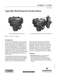
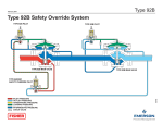
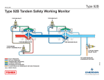
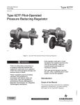
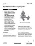
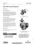
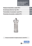
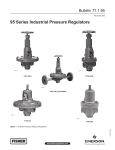
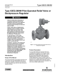
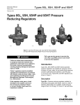
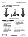
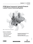
Type 92C
Instruction Manual
Form 5135
December 2012
Type 92C Steam Regulator
!
WARNING
Fisher® regulators must be installed,
operated, and maintained in accordance
with federal, state, and local codes, rules
and regulations, and Emerson Process
Management Regulator Technologies,
Inc. instructions.
Introduction
Scope of the Manual
This instruction manual provides installation,
maintenance, and parts ordering information for the
Type 92C steam self-powered control valve and the
Type 6392 pilot. Both the pilot-operated and the
pressure-loaded constructions are covered. The
Type 92C is also available with a Type 6492HM or
6492HTM safety override pilot. The pressure-loading
device and accessories used with this valve are
covered in other manuals.
W3111_2
Figure 1. Type 92C Pilot-Operated Regulator
1301 Series regulator or 670 Series panel-mounted
regulator may be used as the loading regulator.
A Type 6492HM (or 6492HTM) safety override pilot is
also available for the Type 92C. The Type 6392 pilot is
used in a series installation with the Type 6492HM (or
6492HTM) safety override pilot installed on the upstream
valve. The Type 6492HM (or 6492HTM) safety override
pilot senses pressure downstream of the second valve,
and prevents pressure from rising above safe operating
pressure in the event the downstream valve fails. This
system is approved by ASME B31.1-1989, 122.14.2.A,
and can replace an ASME safety valve when vent
piping is not practical and upstream pressure does not
exceed 400 psig / 27.6 bar. Local codes and standards
may require approval by an appropriate authority prior
to installation.
!
Description
The Type 92C steam regulator is a gray cast iron,
steel, or stainless steel pressure-reducing regulator
for steam or hot air service. This regulator is available
with a Type 6392 pilot for use as a pilot-operated
regulator (Figure 1) or without a pilot for use as
a pressure-loaded regulator. The pilot-operated
version uses inlet pressure as the operating medium;
no separate air supply is required. The pressureloaded version is used where remote adjustment of
the regulator pressure setting is required; a 67 or
WARNING
The Type 92C safety override system
does not provide positive shutoff in
dead end service. It is intended for
large distribution systems where steam
leakage will condense before steam
pressure builds up. Downstream piping
and components must be rated for
maximum upstream steam pressure for
dead end service. Failure to do so could
cause personal injury or death.
www.fisherregulators.com
D100255X012
Installation, operation, and maintenance
procedures performed by unqualified
personnel may result in improper
adjustment and unsafe operation. Either
condition may result in equipment damage
or personal injury. Use qualified personnel
when installing, operating, and maintaining
the Type 92C regulator.
Type 92C
Specifications
This section lists the specifications for Type 92C regulator. Additional specifications for an individual regulator are
found on the regulator body and pilot nameplates.
Body Sizes and End Connection Styles
SIZE
NPS 1/2, 3/4, or 1 /
DN 15, 20, or 25
BODY MATERIAL
Gray Cast Iron
Steel or CF8M Stainless Steel
NPT
NPT, CL150 RF, CL300 RF,
or PN 16/25/40
Maximum Allowable Inlet and Pilot
Supply Pressures*
Gray Cast Iron Construction: 250 psig / 17.2 bar
Steel and Stainless Steel Construction:
300 psig / 20.7 bar
Regulator Pressure Drops*
Minimum: 15 psi / 1.0 bar
Maximum Operating: 150 psi / 10.3 bar for
outlet pressure settings equal to or below
50 psig / 3.4 bar; 200 psi / 13.8 bar for outlet
pressure settings above 50 psig / 3.5 bar
Maximum Emergency
Gray Cast Iron construction: 250 psi / 17.2 bar
Steel and Stainless Steel construction:
300 psi / 20.7 bar
Outlet Control Ranges
See Table 1
Maximum Outlet Pressures*
Maximum Operating Outlet Pressure:
150 psig / 10.3 bar
Maximum Emergency Outlet (Casing) Pressure
Gray Cast Iron construction: 250 psig / 17.2 bar
Steel and Stainless Steel construction:
300 psig / 20.7 bar
Loading Pressure for Pressure-Loaded Regulator*
See Figure 2 to determine loading pressure.
Maximum allowable loading pressure is 250 psig /
17.2 bar for gray cast iron construction and
300 psig / 20.7 bar for steel or stainless steel
construction; the maximum allowable diaphragm
differential pressure of 150 psi / 10.3 bar
for gray cast iron, steel, and stainless steel
constructions must not be exceeded.
Orifice Sizes
NPS 1/2 / DN 15 Main Valve:
9/16 inch / 14 mm
NPS 3/4 and 1 / DN 20 and 25 Main Valves:
3/4 inch / 19 mm is standard; 9/16 inch / 14 mm
is optional
Maximum Material Temperature Capabilities(1)
Gray Cast Iron Construction: 406°F / 208°C
Steel and Stainless Steel Construction:
500°F / 260°C
Optional High-Temperature Steel or
Stainless Steel Body: 650°F / 343°C
Pressure Registration
With Pilot: External
Without Pilot: Internal
Downstream Control Line Connection
1/4 NPT (internal) in pilot body (downstream
control line not required for pressureloaded regulator)
Loading Pressure Connection
1/4 NPT (internal) in main valve diaphragm flange
(this connection is factory-piped to the pilot on
pilot-operated regulator)
Pilot Spring Case Vent
3/32-inch / 2.4 mm drilled hole
Approximate Weights
Gray Cast Iron, Steel, or Stainless Steel Body
with Pilot: 20 pounds / 9.1 kg
Gray Cast Iron, Steel, or Stainless Steel Body
without Pilot: 16 pounds / 7.3 kg
1. Pressure/temperature limits in this Instruction Manual and any applicable code limitations must not be exceeded.
2
Type 92C
Note
TYPE 92C REGULATOR
To determine required loading pressure,
add the diaphragm differential pressure
to the desired outlet pressure setting.
PILOT LOADING LINE
PILOT SUPPLY
DIAPHRAGM DIFFERENTIAL (psi)
2
4
20
6
8
10
12
3/4-inch / 19 mm
orifice size
15
1
10
0.5
9/16 inch / 14 mm
orifice size
5
0
50
100
150
200
DIAPHRAGM DIFFERENTIAL (bar)
PRESSURE DROP ACROSS VALVE (bar)
DOWNSTREAM
CONTROL LINE
TYPE 6392 PILOT
TOP VIEW OF REGULATOR AND
PILOT CONNECTIONS
TYPE 6392 PILOT
DOWNSTREAM
CONTROL LINE
STRAINER
TYPE 92C REGULATOR
PRESSURE DROP ACROSS VALVE (psi)
26A3808-A
A2508-1
16A1548-B
A2522-1
BYPASS LINE
Figure 3. Typical Pilot-Operated Type 92C
Regulator Installation
Figure 2. Diaphragm Differential Pressure
for Pressure-Loaded Regulator
Table 1. Safety Pilot Outlet (Control) Pressure Ranges
SPRING RANGE
TYPE
6492HM
6492HTM
SPRING COLOR
MINIMUM PRESSURE AT WHICH MONITORING
PILOT CAN BE SET
0.69 to 2.1
Yellow
5 psig / 0.34 bar over normal distribution pressure
1.7 to 5.2
Green
70 to 150
4.8 to 10.3
Red
80 to 250
5.4 to 17.2
15 to 100
1.0 to 6.9
psig
bar
10 to 30
25 to 75
10 psig / 0.69 bar over normal distribution pressure
Unpainted
Table 2. Outlet Pressure Ranges
SPRING USAGE
Standard use up to
500°F / 260°C
High-pressure and/or High
temperature over 500°F / 250°C
OUTLET PRESSURE RANGE
psig
bar
SPRING PART NUMBER
AND COLOR
5 to 70
0.34 to 4.8
20 to 150
15 to 100
80 to 200
SPRING WIRE DIAMETER
SPRING FREE LENGTH
Inches
mm
Inches
mm
1E392627012, Green
0.170
4.32
2.00
50.8
1.4 to 10.3
1E392727142, Red
0.207
5.26
1.94
49.0
1.0 to 6.9
14B9941X012, Unpainted
0.192
4.88
5.5 to 17.2
14B9940X012, Unpainted
0.282
7.16
1.96
49.8
Table 3. Flow Coefficients(1)
ORIFICE SIZE
WIDE-OPEN FOR RELIEF SIZING
Inches
mm
Cg
Cs
Cv
9/16
14
170
8.5
5
3/4
19
240
12
7.1
C1
Km
34
0.67
1. Cv = Cs x 20 ÷ C1
Table 4. IEC Sizing Coefficients
ORIFICE SIZE
BODY SIZE
9/16 inch / 14 mm
NPS
DN
1/2
15
3/4 or 1
20 or 25
XT
0.73
FD
0.38
0.44
3/4 inch / 19 mm
FL
0.82
XT
FD
FL
----
----
----
0.73
0.38
0.82
3
Type 92C
TYPE 92C MAIN VALVE
TYPE 92C MAIN VALVE
TYPE 6392 PILOT
TYPE 6392 PILOT
TYPE 6492HM SAFETY
OVERRIDE PILOT
TOP VIEW
TYPE 6492HM SAFETY
OVERRIDE PILOT
TYPE 6392 PILOT
TYPE 6392 PILOT
TYPE 92C MAIN VALVE
TYPE 92C MAIN VALVE
SIDE VIEW
E0656
BLOCK VALVE
TYPE 6492HM SAFETY
OVERRIDE PILOT
TYPE 6392 PILOT
TYPE 6392 PILOT
GAUGE
GAUGE
GAUGE
BLOCK VALVE
E0657
TYPE 92C MAIN VALVE
BLOCK VALVE
TYPE 92C MAIN VALVE
TYPICAL TYPE 92C WITH TYPE 6492HM OR 6492HTM SAFETY OVERRIDE PILOT INSTALLATION
Figure 3. Typical Pilot-Operated Type 92C Regulator Installations (continued)
4
Type 92C
Principle of Operation
Pilot-Operated Regulator
Refer to Figure 5. Pilot supply pressure is piped from
the inlet side of the main valve to the pilot inlet
connection. Downstream pressure registers under the
main valve diaphragm through the pitot tube and under
the pilot diaphragm through the downstream control line.
When downstream pressure decreases to a value
below the setting of the pilot regulator spring, the pilot
spring forces the pilot valve plug open, increasing
the loading pressure on the top of the main valve
diaphragm. The increased loading pressure on top of
the main valve diaphragm and decreased downstream
pressure under the main valve diaphragm force the
main valve diaphragm and stem downward. This
opens the main valve plug, and increases flow to
the downstream system, thus restoring downstream
pressure to the setting of the pilot regulator spring.
When downstream pressure increases it registers
under the pilot diaphragm and overcomes the force of
the pilot spring. This allows the pilot valve spring to
close the pilot valve plug and causes excess loading
pressure to bleed to the downstream system through
the pilot bleed hole. At the same time, increased
downstream pressure registers under the main valve
diaphragm. The decreased loading pressure on top of
the main valve diaphragm and increased downstream
pressure under the main valve diaphragm force
the main valve diaphragm upward. This allows the
main valve plug spring to close the main valve plug,
reducing flow to the downstream system.
Pressure-Loaded Regulator
Refer to Figure 7. With a pressure-loaded regulator, a
remote, adjustable loading regulator provides loading
pressure to the top of the main valve diaphragm.
Downstream pressure registers under the main valve
diaphragm through the pitot tube.
When downstream pressure decreases, it registers
under the diaphragm and allows the stem and plug
to move downward, thereby opening the valve to
increase downstream pressure.
When downstream pressure increases, it registers
under the diaphragm and forces the stem and plug
to move upward. The upward force of the spring
causes the valve to close, which decreases flow to
the downstream system thus decreasing downstream
pressure. In hot air service, supply air above the
diaphragm becomes compressed and is vented to the
atmosphere. If a steam supply is used, the steam is
vented downstream.
Safety Override Pilot Principle
of Operation
Refer to Figure 6. Once placed in operation, the
upstream Type 6392 pilot senses the intermediate
pressure between both valves, and the Type 6492HM
(or 6492HTM) pilot senses downstream pressure of
the second valve. As demand for flow increases,
intermediate pressure will fall causing the Type 6392
pilot to open. As the Type 6392 pilot valve opens,
loading pressure to the main valve increases, opening
the main valve.
The Type 6492HM (or 6492HTM) safety override
pilot remains open because its setpoint is above
the setpoint of the downstream valve. In the
unlikely event that the downstream valve fails open,
downstream pressure will rise above the downstream
valve’s setpoint. This pressure is sensed by the
Type 6492HM (or 6492HTM) safety override pilot. As
downstream pressure increases the safety override
pilot closes, reducing loading pressure to the main
valve, which positions the main valve to maintain
downstream pressure as specified per ASME Boiler
and Pressure Vessel Code, section VIII.
In the event that the upstream valve fails, the
downstream regulator will prevent downstream
pressure from rising above safe operating levels.
It is recommended to install some type of warning
system, such as a sentinel relief valve, to warn the
operator that a valve has failed in the system. This
will prevent prolonged operation with one valve, which
could cause valve trim wear and noise associated with
operation at high differential pressures.
When operating in most steam systems, valve
setpoints should be in strict accordance to
ASME Boiler and Pressure Vessel Code, section VIII.
The Type 6492HM (or 6492HTM) safety override
pilot should be set at 10 psig / 0.69 bar or 10% above
maximum downstream operating pressure of the
second valve, whichever pressure is greater. For
example, most HVAC systems operate at 15 psig /
1.0 bar, so the safety override pilot should be set no
higher than 25 psig / 1.7 bar.
5
Type 92C
LOADING REGULATOR
BLEED RESTRICTION
OPTIONAL PIPING FOR
STEAM LOADING
STRAINER
TYPE 92C REGULATOR
BYPASS LINE
16A1547-A
A2523-1
Figure 4. Typical Pressure-Loaded Type 92C Regulator Installation
Installation
!
WARNING
Personal injury, equipment damage,
or leakage due to escaping steam
or bursting of pressure-containing
parts may result if this regulator is
overpressured or is installed where
service conditions could exceed the
limits given in Specifications section on
page 2 and on the appropriate nameplate,
or where conditions exceed any ratings
of the downstream piping or piping
connections. To avoid such injury or
damage, provide pressure-relieving or
pressure-limiting devices to prevent
service conditions from exceeding
those limits. Type 92C regulators and
their installations should be checked
for compliance with all applicable codes
such as the ANSI B31.1-1977 Power
Piping standard and the ASME Boiler and
Pressure Vessel code.
Use a qualified personnel when installing, operating,
and maintaining a Type 92C regulator. Make sure
that there is no damage to or foreign material in the
regulator and that all tubing and piping are clean
and unobstructed. Install the regulator so that flow
direction matches the arrow marked on the regulator
body. Some typical Type 92C regulator installations
are shown in Figures 3 and 4.
The Type 92C regulator may be installed in any
orientation. However, the regulator should not be
6
installed in a tall vertical pipeline where condensate
could collect and create a pressure head affecting
regulator performance.
Apply steam-compatible pipe compound to the
external pipeline threads. Then, using acceptable
piping procedures, install the regulator into
the pipeline.
If continuous operation of the system is required
during inspection and maintenance, install a threevalve bypass around the regulator. If the flowing
medium contains solids, install a proper size strainer
upstream of the regulator.
Pilot-Operated Regulator
The Type 6392 pilot has three 1/4 NPT connections
located in the pilot body. For proper operation of
a pilot-operated regulator, the pilot supply and the
regulator loading connections should be installed
parallel to the flow direction arrow marked on the pilot
body as shown in Figure 10, and the downstream
control line should be installed in the pilot body
connection as shown in Figures 3 and 10. If a pilotoperated regulator is ordered, the pilot supply and
the regulator loading connections will be made at
the factory.
Note
Pilot is shown here above the main valve
body for illustration purposes only. See
Figures 1 and 10 for actual pilot position
and appearance of pilot-supply line and
loading-pressure tubing.
Type 92C
July 2008
Type 92C Safety Override System
Typ
PILOT REGULATING SPRING
PILOT DIAPHRAGM
DOWNSTREAM BLEED HOLE
DOWNSTREAM
CONTROL LINE
PILOT
SUPPLY
PILOT
VALVE
PLUG
PILOT
VALVE
SPRING
MAIN VALVE
DIAPHRAGM
PITOT
TUBE
Typ
MAIN VALVE PLUG
July 2008
MAIN VALVE SPRING
Type 92C Safety Override System
36A1546-B
A2520-1
Type 92C
INLET
PRESSURE
INLET
PRESSURE
OUTLET
PRESSURE
July 2008
OUTLET
PRESSURE
ATMOSPHERIC
PRESSURE
ATMOSPHERIC
PRESSURE
LOADING
PRESSURE
LOADING
PRESSURE
Type
92CPRESSURE
Safety Override System
INTERMEDIATE
Figure 5. Operational Schematic of Pilot-Operated Type 92C Regulator
TYPE 6492HM SAFETY
OVERRIDE PILOT
TYPE 6392 PILOT
TYPE 6392 PILOT
TYPE 92C MAIN VALVE
INLET PRESSURE
OUTLET PRESSURE
ATMOSPHERIC
PRESSURE
INLET
PRESSURE
INLET
PRESSURE
LOADING
PRESSURE
OUTLET
PRESSURE
OUTLET
PRESSURE
INTERMEDIATE PRESSURE
ATMOSPHERIC
PRESSURE
ATMOSPHERIC
PRESSURE
LOADING
PRESSURE
LOADING
PRESSURE
INTERMEDIATE
PRESSURE
INTERMEDIATE
PRESSURE
TYPE 92C MAIN VALVE
E0557
E0658
Figure 6. Type 92C with Type 6492HM Safety Override Pilot Operational Schematic
7
Type 92C
Note
Since a clogged vent may cause
improper regulator functioning, install
and maintain the Type 92C regulator so
that the Type 6392 pilot spring case vent
remains clear and unobstructed.
To install a pilot-operated regulator:
1. C
onnect a downstream control line of at least
1/4-inch / 6.4 mm diameter pipe bushed down
to the 1/4 NPT control line connection in the
pilot body.
2. F
or both body-sized and swaged pipelines, locate
the pipeline control line connection in a section of
straight pipe at least 10 pipe diameters away from
the regulator or swage.
device. In all cases, check the pressure setting to
make sure it is correct for the application.
Startup
The maximum inlet pressure for a specific construction
is stamped on the main valve nameplate. Use
pressure gauges to monitor upstream and downstream
pressures during startup.
To put the regulator into operation:
1. Open the control line shutoff valve.
2. For a pilot-operated regulator, open the
downstream block valve.
For a pressure-loaded regulator, open the shutoff
valve in the pressure-loading piping or tubing.
3. D
o not locate the pipeline control line connection
in an elbow, swage, or other area where
turbulence or abnormal velocities may occur.
3. Slowly open the upstream block valve.
4. If the pilot is mounted with the control line in a
position other than horizontal, make sure the
control line is sloped away from the pilot so that
condensate can drain into the pipeline.
5. T
o adjust the downstream pressure, follow the
appropriate procedure:
4. If a bypass line is used, slowly close the bypass
line block valve.
a. F
or a pilot-operated regulator, loosen the
jam nut (key 15, Figure 9). Turn the adjusting
screw (key 16, Figure 9) into the spring case
to increase the downstream pressure. Turn
the adjusting screw out of the spring case to
decrease the downstream pressure. When the
required downstream pressure is maintained
for several minutes, tighten the jam nut to lock
the adjusting screw in position.
b. F
or a pressure-loaded regulator, refer
to the Instruction Manual of the pressureloading device for downstream pressure
adjustment procedures.
5. Install a shutoff valve (not a needle valve) in
the control line to completely isolate the pilot
during maintenance.
6. Install a pressure gauge in the control line or near
the regulator to aid in setting the outlet pressure.
Each pilot-operated regulator is factory-set
for the pressure setting specified on the order. If
no setting is specified, the unit is factory-set at
30 psig / 2.1 bar. In all cases, check the spring
setting to make sure it is correct for the application.
Pressure-Loaded Regulators
To install a pressure-loaded regulator:
1. Install a shutoff valve in the pressure-loading
piping or tubing.
2. C
onnect the piping or tubing to the 1/4 NPT
connection in the diaphragm flange (key 2, Figure 8).
If the loading regulator used with the pressureloaded regulator does not provide internal relief, an
atmospheric bleed (e.g., no. 60 drill size) is required
if the loading supply is air, or a downstream bleed
line is required if the loading supply is steam. This
installation is shown in Figure 4.
The pressure setting of a pressure-loaded regulator
is adjusted and determined by the pressure-loading
8
Safety Override Pilot Startup
and Adjustment
1. Loosen adjusting screws of the Type 6492HM (or
6492HTM) safety override pilot and Type 6392
intermediate pilot on the upstream valve until there
is no spring load. The screws should turn freely
by hand.
2. Loosen the adjusting screw of the Type 6392
pilot on the downstream valve until there is no
spring load.
3. T
ighten the Type 6492HM (or 6492HTM) safety
override pilot of the upstream valve all the way in
to its highest spring setting.
Type 92C
LOADING REGULATOR
BLEED RESTRICTION
OPTIONAL
PIPING
FOR STEAM
LOADING
8
9
2
15
9
26A1538-A
STEEL/STAINLESS STEEL CONSTRUCTION
MAIN VALVE
DIAPHRAGM
14
12
PITOT TUBE
13
8
9
1
2
10
9
4
6
S
11
7
S
MAIN VALVE PLUG
MAIN VALVE SPRING
36A1546-B
A2947
5
3
26A1536-A
INLET PRESSURE
LOADING PRESSURE
DOWNSTREAM PRESSURE
Figure 7. Operational Schematic of Pressure-Loaded
Type 92C Regulator
GRAY CAST IRON CONSTRUCTION
APPLY SEALANT:
S = ANTI-SEIZE COMPOUND
Figure 8. Type 92C Steam Regulator Assembly
4.
Tighten the Type 6392 pilot of the upstream
valve all the way in to its highest spring setting.
Shutdown
5.
Tighten the Type 6392 pilot of the downstream
valve to the desired downstream pressure.
To take the regulator out of operation:
6.* Loosen the Type 6392 intermediate pilot on
the upstream valve to the desired intermediate
pressure (normally 50% of inlet pressure).
7.
Loosen the Type 6492HM (or 6492HTM) safety
override pilot of the upstream valve until there is
no spring load.
8.
Tighten the Type 6392 pilot of the downstream
valve all the way in to its highest spring setting.
9.
Tighten the Type 6492HM (or 6492HTM) safety
override pilot of the upstream valve to desired
pressure as specified per ASME Boiler and
Pressure Vessel Code, section VIII.
10.* L
oosen the Type 6392 pilot of the
downstream valve to the desired downstream
pressure setpoint.
*Fisher® recommends establishing setpoint by tightening the adjusting screw.
1. If a bypass line is used, slowly open the
bypass line block valve while monitoring the
downstream pressure.
2. Close the upstream block valve.
3. F
or a pilot-operated regulator, close the
downstream block valve.
For a pressure-loaded regulator, close the
shutoff valve in the pressure-loading piping
or tubing.
4. Close the control line shutoff valve.
5. Vent the regulator, the control line, and the pilot
supply line to release any trapped pressure.
Maintenance
Regulator parts are subject to normal wear and must be
inspected periodically and replaced as necessary. The
frequency of inspection and replacement depends upon
the severity of service conditions and upon applicable
Federal, state, and local codes and regulations.
9
Type 92C
!
WARNING
Avoid personal injury or property damage
from sudden release of pressure or
uncontrolled steam or other process
fluid. Before starting disassembly:
• Isolate the regulator from the process,
• Release process pressure, and
• V
ent the pilot supply and main valve
loading pressures.
4. Install the stem assembly (key 11) in the stem
guide bushing (key 6). Place one diaphragm
gasket (key 9) in the regulator body (key 1).
For Steel/Stainless Steel constructions, place the
diaphragm ring (key 15) and another diaphragm
gasket (key 9) on top of the first gasket.
For all constructions, place the two molded
diaphragms (key 8) with the raised circle up,
another diaphragm gasket, and the diaphragm
flange (key 2) on the body. Insert and tighten the
cap screws (key 12).
This section contains separate procedures for regulator
and pilot maintenance.
5. F
or the pilot-operated regulator, reconnect
the elbow, the loading tubing, and the connector
(keys 25, 22, and 24, Figure 10).
Type 92C Regulator
For the pressure-loaded regulator, reconnect
the pressure-loading tubing.
Perform these procedures when replacing diaphragm,
the stem assembly, the valve plug, or the orifice. Refer
to the correct section for the required instructions. Key
numbers refer to Figure 8 unless otherwise indicated.
The regulator may remain in the pipeline during
maintenance procedures unless the valve body is to
be replaced or removed for repairs. For pilot-operated
regulators, the pilot may remain on the pipe nipple
(key 23, Figure 10) unless the pilot body (key 1,
Figure 9) is to be removed or the entire pilot replaced
as a unit.
Replacing Diaphragm and Stem Assembly
1. F
or the pilot-operated regulator, unscrew the
elbow and connector (keys 25 and 24, Figure 10)
so that the loading tubing (key 22, Figure 10) can
be removed.
6. When maintenance is completed, refer to the
Startup section to put the regulator back in
operation and to adjust the pressure setting.
Replacing Valve Plug and Orifice
1. Remove the valve plug guide (key 5).
2. Remove the valve plug (key 4) and the valve
plug spring (key 7). Inspect the valve plug
seating surface for nicks or scratches. Replace
as necessary.
3. Unscrew the orifice (key 3), and inspect the
seating surface for nicks and scratches. Replace
if necessary.
4. Clean the valve plug guide, the valve plug, the
valve plug spring, and the orifice (keys 5, 4, 7,
and 3, respectively).
For the pressure-loaded regulator, unscrew
the loading tubing (customer supplied) from the
1/4 NPT connection in the regulator diaphragm
flange (key 2).
5. Coat the orifice threads with Never-Seez* or
equivalent lubricant. Then, being careful not to
damage the seating surface, thread the orifice
(key 3) into the regulator body (key 1).
2. Remove the cap screws (key 12) and the diaphragm
flange (key 2).
6. Place the valve plug spring (key 7) into the
valve plug guide (key 5). Then slide the valve
plug (key 4) over the spring and into the valve
plug guide.
Lift out the upper diaphragm gasket (key 9), the
diaphragms (key 8), the lower diaphragm gasket,
and for Steel/Stainless Steel constructions, the
diaphragm ring (key 15), and another diaphragm
gasket (key 9).
3. L
ift out the stem assembly (key 11) consisting of
the pusher plate and the stem. Check that the
pitot tube (key 10) is clear and free of obstructions.
Clean the parts. Check for wear, scratches, nicks
and other damage, and replace parts as necessary.
10
7. A
pply Lok-Cease 20/20† sealant or equivalent
to the valve plug guide threads, and screw the
valve plug guide (key 5) with attached parts
into the regulator body (key 1), applying 130 to
160 foot-pounds / 176 to 217 N•m of torque.
* Trademark of Never-Seez Corp.
† Trademark of Certified Laboratories
Type 92C
15
16
L
2
18
14
19
13
9
17
8
7
L
26
1
4
10
S
6
11
3
5
12
16A1520-B
APPLY LUBRICANT/SEALANT:
L = ANTI-SEIZE LUBRICANT
S = ANTI-SEIZE COMPOUND
Figure 9. Type 6392 Pilot Assembly
25
22
24
23
1/4 NPT PILOT
SUPPLY CONNECTION
1/4 NPT REGULATOR
SUPPLY CONNECTION
1/4 NPT DOWNSTREAM
CONTROL LINE CONNECTION
36A1545-A
A2521-1
Figure 10. Type 6392 Pilot Mounting Parts
11
Type 92C
8. W
hen maintenance is completed, refer to the
Startup section to put the regulator back in
operation and to adjust the pressure setting.
Type 6392 Pilot
Perform this procedure if inspecting, cleaning, or
replacing any pilot parts. Key numbers refer to Figure 9
unless otherwise specified.
All pilot maintenance may be performed with the pilot
body (key 1) attached to the pipe nipple and connector
(keys 23 and 24, Figure 10) unless the pilot body must
be removed or the pilot is to be replaced as a unit.
1. L
oosen the jam nut (key 15), and turn the
adjusting screw (key 16) counterclockwise until all
compression is removed from the control spring
(key 13). Remove the loading tubing from the
pilot outlet connection. Remove the cap screws
(key 17), spring case (key 2), control spring
(key 13), and upper spring seat (key 14) from
the body.
2. Remove the lower spring seat (key 9), the diaphragm
(key 7), and the diaphragm gasket (key 8) from
the body. Lift out the stem assembly (key 6)
consisting of the stem and the pusher plate.
Clean the 1/16-inch / 1.6 mm diameter pilot bleed
hole. Clean and replace parts as necessary, and
assemble the stem assembly, the gasket, the
diaphragm, and the spring seat in the order shown
in Figure 9.
3. Install the control spring (key 13), the lubricated
upper spring seat (key 14), and the spring case
(key 2). Insert and tighten the cap screws (key 17).
Lubricate the adjusting screw (key 16) with
Never-Seez* or equivalent lubricant, and thread it
into the spring case.
4. Unscrew the valve plug guide (key 5). Remove
the strainer screen (key 12), the valve plug
(key 4), the valve plug cap (key 26), and the
valve plug spring (key 11). Unscrew the orifice
(key 3). Clean and replace parts as necessary.
Apply Never-Seez* or equivalent lubricant to the
orifice threads, and screw the orifice into place.
5. P
lace the valve plug spring (key 11) into the valve
plug guide (key 5). Insert the valve plug cap
(key 26) into the valve plug (key 4), and then slide
both parts over the spring and into the valve plug
guide. Place the strainer screen (key 12) onto the
valve plug guide. Apply Lok-Cease 20/20† sealant
* Trademark of Never-Seez Corp.
† Trademark of Certified Laboratories
12
or equivalent (key 21) to the valve plug guide
threads, and screw the valve plug guide with the
attached parts into the pilot body (key 1).
6. When maintenance is completed, refer to the
Startup section to put the regulator back into
operation, and adjust the pressure setting.
Types 6492HM and 6492HTM
Safety Override Pilots
These procedures are to be performed if inspecting,
cleaning, or replacing any pilot parts, or of cycling,
erratic control, or too high or too low an outlet (control)
pressure is noted. Perform only those procedures
in this section required to correct the problem. Key
numbers refer to Figure 11.
Note
Before performing any maintenance,
loosen the hex nut (key 16), if used,
and turn the adjusting screw (key 15) or
handwheel (key 31) counterclockwise
until all compression is removed from
the control spring (key 12). Remove the
pilot spring from the pipe nipple and
connectors (keys 82 and 83, Figure 12).
1. Unscrew the plug guide (key 2). Remove the
screen (key 77), inner valve (key 4), plug spring
(key 3), and stem (key 7). Unscrew the orifice
(key 5). Examine the orifice and plug seating
surfaces for damage.
2. Clean and replace parts as necessary. Apply
sealant to the orifice threads. Thread the orifice
into place and tighten using 19 to 25 foot-pounds /
26 to 34 N•m of torque.
3. Handle parts carefully, and place the plug spring
(key 3) in the plug guide (key 2). Slide the inner
valve (key 4) over the spring and into the plug
guide. Place the screen (key 77) onto the plug
guide. Place the stem (key 7) in the center hole
of the plug guide. Apply sealant to the plug guide
threads, and screw the guide plus attached parts
into the body (key 1).
4. Remove the pipe plug (key 74). Then remove the
pipe plug (key 94). Clean and replace the pipe
plugs as necessary.
5. A
pply sealant to the threads of the pipe plug
(key 94) and install.
Type 92C
15
16
13
11
14
12
20
10
9
18
8
5
7
19
95
17
94
77
1
74
78
4
3
2
E0660
Figure 11. Type 6492HM or 6492HTM Safety Override Pilot Assembly
TYPE 6492HM
TYPE 6392
84
82
81
83
91
82
E0659
Figure 12. Type 92C with Safety Override Pilot Assembly
13
Type 92C
6. Apply sealant to the threads of the pipe plug
(key 74). Thread the pipe plug into place and
tighten using 5 to 15 foot-pounds / 6.8 to 20 N•m
of torque.
7. Remove the cap screws (key 17), spring case
(key 14), control spring (key 12), and upper
spring seat (key 13) from the body (key 1).
8. Remove the lower spring seat (key 11),
diaphragms (key 10), and diaphragm gasket
(key 18) from the body. Inspect and clean the
diaphragm gasket, and replace if necessary.
9. Unscrew the bellows retainer (key 8) and remove
the bellows (key 9). Replace worn parts as
necessary, and install the bellows and bellows
retainer. Tighten the bellows retainer using 19 to
25 foot-pounds / 26 to 34 N•m of torque.
10. Install the diaphragm gasket. Install both
diaphragms with their raised performed centers
facing toward the spring case.
11. L
ubricate the upper spring seat and the exposed
threads of the adjusting screw. Install the lower
spring seat (key 11), control spring (key 12),
upper spring seat (key 13), and spring case
(key 14). Insert and tighten the cap screws
(key 17) in a crisscross bolting pattern using
12 to 18 foot-pounds / 16 to 24 N•m of torque.
Parts Ordering
When corresponding with your local Sales Office about
this equipment, always specify the equipment serial
number as found on the regulator nameplate.
When ordering replacement parts, specify the
complete 11-character part number of each needed
part as found in the following parts list.
Parts List
Regulator
Key Description
1
Regulator Body Assembly with Bushing
(See key 6 for bushing)
Gray Cast Iron
NPS 1/2 / DN 15
NPS 3/4 / DN 20
NPS 1 / DN 25
Steel
1/2 NPT
3/4 NPT
1 NPT
Part Number
36A1539X012
36A1540X012
36A1541X012
36A1542X012
36A1543X012
36A1544X012
Key Description
*Recommended spare part
14
Part Number
1
Regulator Body Assembly with Bushing (continued)
Steel (continued)
CL150 RF
NPS 1/2 / DN 15
14B3428X012
NPS 3/4 / DN 20
14B3428X022
NPS 1 / DN 25
19A5459X012
CL300 RF
NPS 1/2 / DN 15
14B3428X032
NPS 3/4 / DN 20
14B3428X042
NPS 1 / DN 25
14B0037X012
PN 16/25/40 RF
NPS 1/2 / DN 15
14B3428X052
NPS 3/4 / DN 20
14B3428X062
NPS 1 / DN 25
14B3428X072
Stainless Steel
1/2 NPT
36A1542X022
3/4 NPT
36A1543X032
1 NPT
36A1544X022
CL150 RF
NPS 1/2 / DN 15
14B3428X082
NPS 3/4 / DN 20
14B3428X092
NPS 1 / DN 25
19A5459X022
CL300 RF
NPS 1/2 / DN 15
14B3428X102
NPS 3/4 / DN 20
14B3428X112
NPS 1 / DN 25
14B0037X022
PN 16/25/40 RF
NPS 1/2 / DN 15
14B3428X122
NPS 3/4 / DN 20
14B3428X132
NPS 1 / DN 25
14B3428X142
2
Diaphragm Flange
Gray Cast Iron
26A1533X012
Steel
26A1534X012
Stainless Steel
26A1534X022
3
Orifice
For 1/2 and 3/4 NPT body,
9/16 inch / 14 mm, 416 Stainless Steel
16A1529X012
For 1 NPT body
3/4 NPT / 19 mm, 416 Stainless Steel
16A1529X012
For 3/4 and 1 NPT body,
9/16 inch / 14 mm, Ethylenepropylene (EPDM),
410/416 Stainless Steel
1E399535132
4
Valve Plug, heat-treated, 416 Stainless Steel
1E398146172
5
Valve Plug Guide
Brass (for Gray Cast Iron body)
1E398214012
416 Stainless Steel (for Steel/Stainless Steel body)1E398235132
6
Stem Guide Bushing, heat-treated
416 Stainless Steel (included in key 1)
For Gray Cast Iron body
1E398535132
For Steel/Stainless Steel body
16A1530X012
7 Valve Plug Spring, Stainless Steel
1E398837022
8* Diaphragm, Stainless Steel (2 required)
1E399236012
9* Diaphragm Gasket
(2 required for Gray Cast Iron body;
3 required for Steel/Stainless Steel body with
Ethylenepropylene (EPDM) seat)
16A1526X012
Steel/Stainless Steel body with metal seat,
3 required
1E3993X0012
Steel/Stainless Steel body with metal seat
(High temperature), 3 required
16A1526X022
10 Pitot Tube
For Gray Cast Iron body, Copper
NPT
16A1525X012
For Steel body, Copper
NPT
1E399417012
CL150 RF
16A1525X012
CL300 RF and PN 16/25/40
1E399417012
Type 92C
Key Description
10 Pitot Tube (continued)
For Stainless Steel body, 304 Stainless Steel
NPT
CL150 RF
CL300 RF and PN 16/25/40
11 Stem Assembly, 416 Stainless Steel
12 Cap Screw, Zinc-plated steel (8 required)
For Gray Cast Iron body
For Steel/Stainless Steel body
14 Drive Screw, Stainless Steel (2 required)
15 Diaphragm Ring
For Steel body, Steel
For Stainless Steel body, Stainless Steel
Part Number
Key Description
1E399438072
16A1525X022
1E399438072
16A1524X012
1A914524052
1A782024052
1A368228982
16A1531X012
16A1531X022
Type 6392 Pilot (See Figure 10)
Key Description
1
Pilot Body
Gray Cast Iron
Steel
Stainless Steel
2
Spring Case
Gray Cast Iron
Steel
Stainless Steel
3
Orifice, heat-treated
416 Stainless Steel
4
Valve Plug, heat-treated
416 Stainless Steel
5
Valve Plug Guide
Brass (for Gray Cast Iron pilot)
Heat-treated, 416 Stainless Steel
(For Steel pilot)
For Gray Cast Iron and Steel pilot,
Heat-treated, 416 Stainless Steel For Stainless Steel pilot 6
Stem Assembly, 416 Stainless Steel
For Stainless Steel seat
For Ethylenepropylene (EPDM) seat
7
Diaphragm, Stainless Steel (2 required)
8* Diaphragm Gasket
Elastomer seat Stainless Steel seat, Graphite
9
Lower Spring Seat, Aluminum
10 Stem Guide Bushing, 416 Stainless Steel
11 Valve Plug Spring, Stainless Steel
12 Strainer Screen, Stainless Steel
13 Control Spring,
Standard springs, 416 Stainless Steel
5 to 70 psig / 0.34 to 4.8 bar, Green 20 to 150 psig / 1.4 to 10.3 bar, Red Spring for use over 500°F / 260°C,
17-7 PH Stainless Steel
15 to 100 psig / 1.0 to 6.9 bar
20 to 25 psig / 1.4 to 1.7 bar
14 Upper Spring Seat, Zinc-plated steel
15 Jam Nut, Plate steel
16 Adjusting Screw, Plated steel
17 Cap Screw, Zinc-plated steel (6 required)
For Gray Cast Iron body
For Steel/Stainless Steel body
26 Valve Plug Cap, heat-treated
416 Stainless Steel
Type 6392 Pilot Mounting Parts
Part Number
26A1518X012
26A1517X012
26A1517X022
2E391219012
2J127522012
2J1275X0012
16A1511X012
16A1516X012
1E391814012
1E391835132
1E391835132
1E391835072
16A1515X012
16A1515X022
1E392836012
1E393104022
1E3931X0012
1E392309012
1E392235132
1E392437022
16A1512X012
1E392627012
1E392727142
14B9941X012
14B9940X012
1B798525062
1A352224122
1E639928992
1A407824052
1A391724052
16A1549X012
22 Loading Tubing
Copper Stainless Steel
23 Pipe Nipple, Steel
24 Connector
Brass Stainless Steel
25 Elbow
Brass Stainless Steel
Part Number
16A1527X012
16A1527X022
1N584226232
15A6002X212
15A6002X642
15A6002X172
15A6002X632
Types 6492HM and 6492HTM
Safety Override Pilots (See Figure 12)
Key Description
1
Pilot Valve Body
WCC Steel
CF8M Stainless Steel
2
Valve Guide, Stainless Steel
Steel body, 416 Stainless Steel
Stainless Steel body, 316 Stainless Steel
3
Valve Spring, 302 Stainless Steel
4
Inner Valve
Steel body, 416 Stainless Steel
Stainless Steel body, 316 Stainless Steel
5
Orifice
Steel body, 416 Stainless Steel
Stainless steel body, 316 Stainless Steel
7
Valve Stem
Steel body, 410/416 Stainless Steel
Stainless Steel body, 316 Stainless Steel
8
Bellows Retainer
Steel body, Brass
Stainless Steel body, 316 Stainless Steel
9 Bellows
Steel body, Brass
Stainless Steel body, 321 Stainless Steel
10 Diaphragm, 302 Stainless Steel (2 required)
11 Lower Spring seat
Type 6492HM, Aluminum
Type 6492HTM
Steel
Stainless Steel
12 Spring
Type 6492HM, Steel
10 to 30 psig / 0.69 to 2.2 bar
25 to 75 psig / 1.7 to 5.2 bar
70 to 150 psig / 4.8 to 10.3 bar
Type 6492HTM, Stainless Steel
15 to 100 psig / 1.0 to 6.9 bar
80 to 250 psig / 5.5 to 17.2 bar
13 Upper Spring seat, Steel
Type 6492HM
Type 6492HTM
14 Spring Case
Steel
With standard adjusting screw
With sealed adjusting screw
Stainless Steel
With standard adjusting screw With sealed adjusting screw 15 Adjusting Screw, Steel
Standard
Handwheel
16 Hex Nut, Zinc-plated steel
Part Number
22A0403X052
22A0403X072
1E391835132
1E391835072
1E392437022
1F967446172
1F9674X0012
1H564446172
1H5644X0012
1F967835132
1F9678X0012
1F971214012
1F9712X0012
1F971318992
1F9713X0012
1E395836012
1E395408012
1E3954X0052
14B9948X012
1E395627022
1D7455T0012
1E395727192
14B9943X012
14B9942X012
1D667125072
14B9951X012
2L416322012
2L442022012
2L416333092
2L4420X0012
1D995448702
1J496428982
1A353724122
*Recommended spare part
15
Type 92C
Types 6492HM and 6492HTM
Safety Override Pilots
(See Figure 12) (continued)
Key Description
17 Cap Screw (8 required)
Type 6492HM
Steel
Stainless Steel
Type 6492HTM
Steel Stainless Steel 18 Diaphragm Gasket
Type 6492HM, Composition
Type 6492HTM, Graphite
34 Machine Screw for use with handwheel, Steel
38 Handwheel, Zinc
39 Lock Washer for use with handwheel, Steel
74 Pipe Plug
Steel
Stainless Steel
77 Screen, 304 Stainless Steel
78 Reducing Bushing
Steel
Stainless Steel
87 Sealed Adjusting Screw Sealing Washer
94 Pipe Plug, Stainless Steel
95 Warning Label
Type 6492HM Pilot Mounting Parts
Key Description
Part Number
1A381624052
1A3816X0152
1A3816X0132
1A3816X0152
Part Number
81 Tubing
82 Pipe Nipple (2 required)
Steel
Stainless Steel
83 Connector
Steel
Stainless Steel
84 Elbow
Steel
Stainless Steel
0500103809W
1C559926232
1C5599X0012
15A6002XY72
15A6002X642
15A6002XY52
15A6002X632
1E396104022
1E3961X0012
16A5763X012
1J496144012
1A352332992
0Z020128992
0Z020135072
16A1512X012
1C379026232
1C3790X0012
1V205699012
1E823135042
19B0429X0A2
Industrial Regulators
Natural Gas Technologies
TESCOM
Emerson Process Management
Regulator Technologies, Inc.
Emerson Process Management
Regulator Technologies, Inc.
Emerson Process Management
Tescom Corporation
USA - Headquarters
McKinney, Texas 75069-1872, USA
Tel: +1 800 558 5853
Outside U.S. +1 972 548 3574
USA - Headquarters
McKinney, Texas 75069-1872, USA
Tel: +1 800 558 5853
Outside U.S. +1 972 548 3574
USA - Headquarters
Elk River, Minnesota 55330-2445, USA
Tels: +1 763 241 3238
+1 800 447 1250
Asia-Pacific
Shanghai 201206, China
Tel: +86 21 2892 9000
Asia-Pacific
Singapore 128461, Singapore
Tel: +65 6770 8337
Europe
Selmsdorf 23923, Germany
Tel: +49 38823 31 287
Europe
Bologna 40013, Italy
Tel: +39 051 419 0611
Europe
Bologna 40013, Italy
Tel: +39 051 419 0611
Chartres 28008, France
Tel: +33 2 37 33 47 00
Asia-Pacific
Shanghai 201206, China
Tel: +86 21 2892 9499
Middle East and Africa
Dubai, United Arab Emirates
Tel: +971 4811 8100
For further information visit www.fisherregulators.com
The Emerson logo is a trademark and service mark of Emerson Electric Co. All other marks are the property of their prospective owners. Fisher is a mark owned by Fisher Controls International LLC,
a business of Emerson Process Management.
The contents of this publication are presented for informational purposes only, and while every effort has been made to ensure their accuracy, they are not to be construed as warranties or
guarantees, express or implied, regarding the products or services described herein or their use or applicability. We reserve the right to modify or improve the designs or specifications of such
products at any time without notice.
Emerson Process Management Regulator Technologies, Inc., does not assume responsibility for the selection, use or maintenance of any product. Responsibility for proper selection, use and
maintenance of any Emerson Process Management Regulator Technologies, Inc. product remains solely with the purchaser.
©Emerson Process Management Regulator Technologies, Inc., 1979, 2012; All Rights Reserved