1
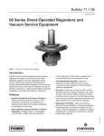
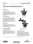
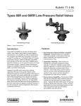
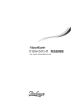
Types 66, 66Z, and 66ZZ
Instruction Manual
Form 1056
November 2008
Types 66, 66Z, and 66ZZ Pressure
Reducing Regulators
!
Warning
Failure to follow these instructions or
to properly install and maintain this
equipment could result in an explosion
and/or fire causing property damage and
personal injury or death.
Fisher® regulators must be installed,
operated, and maintained in accordance
with federal, state, and local codes, rules
and regulations, and Fisher instructions.
If the regulator vents gas or a leak
develops in the system, service to
the unit may be required. Failure
to correct trouble could result in a
hazardous condition.
Call a gas service person to service
the unit. Only a qualified person must
install or service the regulator.
Introduction
W1935-1
Figure 1. Type 66 Self-Operated Pressure
Reducing Regulator
sensitive response to pressure changes by reducing
the unbalanced forces acting on the valve plug. This
regulator and its installation should be checked for
compliance with all applicable codes.
Specifications
This instruction manual provides instructions for
the installation, adjustment, and maintenance
of the Types 66, 66Z, and 66ZZ pressure
reducing regulators. Parts ordering information
is also provided. Other 66 Series regulators and
accessories are covered in other manuals.
Description
The Type 66 self-operated regulator (Figure 1)
maintains a reduced outlet pressure while satisfying
the downstream flow demands. The Types 66Z and
66ZZ self-operated regulators (Figures 8 and 9) also
control a reduced outlet pressure; however, both have
springs sensitive to negative pressures and can be
used for vacuum regulation. Each regulator type has
a balancing diaphragm which increases accurate and
The Specifications table lists the specifications for
the Types 66, 66Z, and 66ZZ self-operated pressure
reducing regulators. Some of the specifications for a
given regulator as it comes from the factory appear on
the regulator nameplate.
Principle of Operation
The cast iron Type 66 regulator uses a pitot tube to
sense outlet pressure while the steel Type 66 regulator
uses an external control line to sense outlet pressure
as shown in Figure 6. Both pressure-sensing methods
register the outlet pressure under the main diaphragm.
When increased downstream demand lowers the outlet
pressure, the lower pressure under the main diaphragm
causes the regulator main spring and valve plug and
stem assembly to open the regulator seat ring and to
supply more gas to the downstream system.
www.emersonprocess.com/regulators
D100247X012
Scope of the Manual
Types 66, 66Z, and 66ZZ
Specifications
Body Sizes and End Connection Styles(1)
construction
Type 66, 66Z,
66ZZ, or 66
vacuum
regulators
or breakers
nominal
Body size,
inch (DN)
END CONNECTION STYLES
AND RATINGS(1)
Standard Cast
Iron Body
Optional Steel
Body
2 (50)
NPT or CL125 FF
NPT (all types),
CL150 RF (all
types), CL150 FF,
CL300 RF
3, 4 (80, 100)
CL125 FF
CL150 RF
Maximum Allowable Inlet Pressures(1)
Emergency Inlet Pressure:
Type 66, 66Z, 66ZZ, or 66 Series Vacuum
Breakers: 25 psig (1,72 bar) positive pressure
66 Series Vacuum Regulators: 8 psig or
16.3-inches of mercury (0,55 bar
differential) vacuum
Maximum Safe Pressure to Avoid Internal
Parts Damage:
Type 66: 10 psig (0,69 bar)
Type 66Z: 5 psig (0,34 bar)
Type 66ZZ: 2 psig (0,14 bar)
66 Series Vacuum Regulators or Breakers:
No more than 1 psig (0,07 bar differential) change
from spring setting
Maximum Operating Inlet Pressure
Recommended for Good Performance:
Type 66, 66Z, or 66 Series Vacuum Breakers:
5 psig (0,34 bar) positive pressure
Type 66ZZ: 2 psig (0,14 bar)
66 Series Vacuum Regulator: 6-inches w.c. or
0.4-inch of mercury (15 mbar differential) vacuum
Maximum Allowable Outlet Pressures
Emergency Outlet (Casing) Pressure:
Type 66, 66Z, or 66ZZ: 8 psig (0,55 bar)
positive pressure
66 Series Vacuum Regulator: 14.7 psi or
29.9-inches of mercury (1,01 bar
differential) vacuum
66 Series Vacuum Breakers: 8 psi or 16.3-inches of mercury (0,55 bar differential) vacuum
Maximum Safe Pressure to Avoid Internal
Parts Damage:
Type 66, 66Z, or 66ZZ: 1 psig (0,07 bar differential) above outlet pressure setting
66 Series Vacuum Regulator: No more
than 1 psig (0,07 bar differential) change from
spring setting
(1)
Maximum Operating Pressure Recommended for Good Performance (66 Series Vacuum Regulators or Breakers Only):
Vacuum Regulators: 10 psig or 20.4-inches of mercury (0,69 bar differential) vacuum
Vacuum Breakers: 6-inches w.c. or 0.4-inch of mercury (15 mbar differential) vacuum
Elastomer Temperature Capabilities
Nitrile (NBR) Standard Elastomers:
-40°to 180°F (-40°to 82°C)
Fluorocarbon (FKM) Elastomers:
0°to 350°F (-18°to 177°C)
Ethylenepropylene (EPDM) Elastomers:
-40°to 275°F (-40° to 135°C)
Pressure Registration
Type 66, 66Z, or 66ZZ
Cast Iron Body: Internal (standard) or external
Steel Body: External (standard) or internal
66 Series Vacuum Regulators or
Breakers: External
Control Line when Used: 3/4-inch NPT standard
Bottom Flange Line when Used: 1/4-inch NPT
standard with removable plug
Spring Case Vent: 3/4-inch NPT standard with
removable Type Y602-10 vent assembly
Outlet (Control) Pressure Ranges
See Tables 1A through 1C
Control Line Connection
3/4-inch NPT
Flow and Sizing Coefficients
See Tables 2 and 3
Approximate Weights
2-inch (DN 50) Body
NPT: 50 pounds (22,7 kg)
Flanged: 55 pounds (25,0 kg)
3-Inch (DN 80) Flanged Body:
100 pounds (45,4 kg)
4-Inch (DN 100) Flanged Body:
155 pounds (70,3 kg)
1. The pressure/temperature limits in this Instruction Manual and any applicable standard or code limitation for valve should not be exceeded.
2
Types 66, 66Z, and 66ZZ
Table 1A. Outlet (Control) Pressure Ranges, 2-inch (DN 50) Body
outlet (Control)
pressure range
construction
Type 66
control spring information
2-inch (DN 50) Body
Inches w.c. Unless
Otherwise
Designated
mbar
4 to 11(1)
8 to 28(1)
Part Number
Color Code
Free Length,
Inches (mm)
Wire Diameter,
Inches (mm)
10 to 27(1)
20 to 70(1)
0B019727052
1E611427022
Purple
None
6.00 (152)
6.00 (152)
0.148 (3,76)
0.200 (5,08)
2 to 5
4 to 8
5 to 12
10 to 20
1D892527022
1D892627022
Brown
Red
6.12 (155)
7.53 (191)
0.109 (2,77)
0.112 (2,85)
7 to 12
10 to 17
14 to 28
17 to 30
25 to 42
35 to 70
1D892727012
1D892827032
1D892927032
Black
Orange stripe
Unpainted
7.88 (200)
7.75 (197)
7.53 (191)
0.130 (3,30)
0.148 (3,76)
0.162 (4,12)
0.75 to 1.5 psig
1 to 2 psig
1.5 to 3 psig
3 to 5 psig
0,05 to 0,10 bar
0,07 to 0,14 bar
0,10 to 0,21 bar
0,21 to 0,34 bar
1D765727032(2)
1D765827032(2)
1D962627032(2)
1N506427142(3)
Unpainted
6.09 (155)
6.00 (152)
6.25 (159)
6.31 (160)
0.207 (5,26)
0.225 (5,72)
0.262 (6,66)
0.283 (7,19)
Brown
6.12 (155)
0.109 (2,77)
5.62 (143)
0.085 (2,16)
5.62 (143)
5.62 (143)
5.62 (143)
0.102 (2,59)
0.095 (2,41)
0.112 (2,85)
Type 66Z
-1 to 2
-2 to 5
1D892527022
Type 66ZZ
-0.25 to 0.25
-0,62 to 0,62
1E991427012
66 Series
vacuum regulators
or breakers
0 to -2
-0.2 to -0.8
-2 to -6
0 to -5
-0,74 to -2
-5 to -15
1J196527012
1H387327012
1N152427012
Unpainted
1. 1 psig (0,07 bar) minimum differential pressure required with this range.
2. Heavy head construction required.
3. Extra heavy head construction required.
Table 1B. Outlet (Control) Pressure Ranges, 3-inch (DN 80) Body
outlet (Control)
pressure range
construction
Type 66
control spring information
3-inch (DN 80) Body
Inches w.c. Unless
Otherwise
Designated
mbar
4 to 11(1)
8 to 28(1)
10 to 27(1)
20 to 70(1)
1D479927032
1D527327022
2 to 5
4 to 8
5 to 12
10 to 20
1D893027022
1D893127012
7 to 12
10 to 17
14 to 28
17 to 30
25 to 42
35 to 70
1D892827032
1D893227032
1D893327032
0.75 to 1.5 psig
1 to 2 psig
1.5 to 3 psig
3 to 5 psig
0,05 to 0,10 bar
0,07 to 0,14 bar
0,10 to 0,21 bar
0,21 to 0,34 bar
1D765827032(2)
1D962627032(2)
1E204427032(2)
1N506527142(3)
Part Number
Color Code
Unpainted
Orange Stripes
Gray with White Stripe
Green
Free Length,
Inches (mm)
Wire Diameter,
Inches (mm)
6.00 (152)
6.00 (152)
0.162 (4,12)
0.207 (5,26)
6.12 (155)
7.12 (181)
0.112 (2,85)
0.125 (3,18)
7.75 (197)
7.50 (191)
7.25 (184)
0.148 (3,76)
0.156 (3,96)
0.182 (4,62)
6.00 (152)
6.25 (159)
6.38 (162)
6.38 (162)
0.225 (5,72)
0.262 (6,66)
0.306 (7,77)
0.362 (9,20)
Type 66Z
-1 to 2
-2 to 5
1D893027022
6.12 (155)
0.112 (2,85)
Type 66ZZ
-0.25 to 0.25
-0,62 to 0,62
1E991527012
8.62 (219)
0.100 (2,54)
66 Series
vacuum regulators
or breakers
0 to -2
-2 to -6
0 to -5
-5 to -15
1J196627012
1K384427012
5.62 (143)
5.62 (143)
0.114 (2,90)
0.120 (3,05)
Unpainted
1. 1 psig (0,07 bar) minimum differential pressure required with this range.
2. Heavy head construction required.
3. Extra heavy head construction required.
3
Types 66, 66Z, and 66ZZ
Table 1C. Outlet (Control) Pressure Ranges, 4-inch (DN 100) Body
outlet (Control)
pressure range
construction
control spring information
4-inch (DN 100) Body
Inches w.c. Unless
Otherwise
Designated
mbar
4 to 11(1)
8 to 28(1)
10 to 27(1)
20 to 70(1)
1D527527022
1D527627032
2 to 5
4 to 8
5 to 12
10 to 20
1D892627022
1D893427022
7 to 12
10 to 17
14 to 28
17 to 30
25 to 42
35 to 70
1D893227032
1D893527032
1D893627032
0.75 to 1.5 psig
1 to 2 psig
1.5 to 3 psig
3 to 5 psig
0,05 to 0,10 bar
0,07 to 0,14 bar
0,10 to 0,21 bar
0,21 to 0,34 bar
Type 66
Free Length,
Inches (mm)
Wire Diameter,
Inches (mm)
7.75 (197)
7.75 (197)
0.170 (4,32)
0.225 (5,72)
7.53 (191)
7.75 (197)
0.112 (2,85)
0.135 (3,43)
Gray
Unpainted
Unpainted
7.50 (191)
7.75 (197)
7.81 (198)
0.156 (3,96)
0.170 (4,32)
0.207 (5,26)
1D771227032(2)
1D771327032(2)
1E204527032(3)
----
Unpainted
Unpainted
Unpainted
----
7.75 (197)
7.75 (197)
7.53 (191)
----
0.262 (6,66)
0.283 (7,19)
0.331 (8,41)
----
Red
7.53 (191)
0.112 (2,85)
Part Number
Color Code
Unpainted
Type 66Z
-1 to 2
-2 to 5
1D892627022
Type 66ZZ
-0.25 to 0.25
-0,62 to 0,62
1E937227012
11.06 (281)
0.112 (2,85)
66 Series
vacuum
regulators
or breakers
0 to -2
-0.2 to -0.8
-2 to -6
0 to 1.5
0 to -5
-0,74 to -2
-5 to -15
0 to 4
1J196727012
1E937227012
1K418127012
1J823827012
11.06 (281)
11.06 (281)
11.50 (292)
11.56 (294)
0.154 (3,91)
0.112 (2,85)
0.162 (4,12)
0.135 (3,43)
Unpainted
1. 1 psig (0,07 bar) minimum differential pressure required with this range.
2. Heavy head construction required.
3. Extra heavy head construction required.
Table 2. Flow Coefficients
outlet
pressure
range,
psig (bar)
droop,
PSIG (bar)
0.75 to 1.5
(0,05 to 0,10)
REGULATING Cg
REGULATING Cv
2-inch
(DN 50)
3-inch
(DN 80)
4-inch
(DN 100)
2-inch
(DN 50)
3-inch
(DN 80)
4-inch
(DN 100)
0.2 (0,01)
0.3 (0,02)
765
1150
1865
2800
3330
5000
21.9
32.9
53.3
80
95.1
143
1 to 2
(0,07 to 0,14)
0.3 (0,02)
0.4 (0,03)
825
1100
1650
2200
3150
4200
23.6
31.4
47.1
62.9
90
120
1.5 to 3
(0,10 to 0,21)
0.4 (0,03)
0.6 (0,04)
665
1000
1165
1750
2500
3750
19
28.6
33.3
50
71.4
107
3 to 5
(0,21 to 0,34)
0.6 (0,04)
0.8 (0,06)
1.0 (0,07)
540
720
900
725
970
1210
----
15.4
20.6
25.7
20.7
27.7
34.6
----
WIDE-OPEN Cg
WIDE-OPEN Cv
2-inch
(DN 50)
3-inch
(DN 80)
4-inch
(DN 100)
2-inch
(DN 50)
3-inch
(DN 80)
4-inch
(DN 100)
C1
1260
3400
5250
36
97.1
150
35
Table 3. IEC Sizing Coefficients
BODY SIZE, INCH (DN)
Xt
2 (50)
3 (80)
4 (100)
4
Fd
Fl
0.35
0.775
0.34
0.30
0.89
Types 66, 66Z, and 66ZZ
air control valve
Remote vent
bypass
line
fan
furnace
optional pressureloading line
vent
Block valves or
plug cocks
block
valve or
plug cock
AD6808
A2495-1
block
valve
block
valve
12 diameter of regulator
size pipe before swage
Swage Nipple
Figure 2. Type 66 Regulator in Pressure-Reducing Application
gas
15A9913-A
A2496-1
Figure 3. Type 66Z Regulator in Gas-Mixing Application
When decreased downstream demand raises the
outlet pressure, the higher pressure under the
main diaphragm opposes the regulator main spring
causing the valve plug and stem assembly to close
the regulator seat ring and to supply less gas to the
downstream system.
The Types 66Z and 66ZZ regulators are identical
to the Type 66 regulator in operation but different
in construction. The Type 66Z regulator (Figure 8)
has a counter spring under the valve plug and disk
assembly which counters the main spring force to
allow settings below atmospheric pressures. The
Type 66ZZ regulator (Figure 9) has a longer spring
case where the main spring, a low rate tension spring,
is stretched between the adjusting screw and the
valve plug stem, also providing below atmospheric
settings and more sensitive pressure regulation than
the Types 66 and 66Z regulators.
Installation
!
Warning
Exposure of the regulator to physical
damage and to corrosive material can
cause improper operation or release of
pressure. Either condition may result
in equipment damage or personal
injury. Properly install the regulator in
a safe location.
caution
Use of this regulator where service
conditions can exceed Specifications
limits may cause equipment damage
or injury to personnel. Be sure the
regulator service conditions do not
exceed Specifications limits.
mixer
VACUUM REGULATOR SET TO OPEN
AT 1.0-INCH W.C. (2,50 mbar) VACUUM
TYPE 66ZZ REGULATOR SET TO OPEN
AT 0.25-INCH W.C. (0,62 mbar) VACUUM
Control lines
filters
0 to 5 psig
(0 to 0,34 bar)
AIR OR INERT
GAS SUPPLY
PRESSURE
BJ9005-B
A2494-2
glove
port
glove
port
to exhaust
header at
9-inches w.c.
(22 mbar)
vacuum
HOOD PRESSURE TO BE KEPT AT
0.23-INCH W.C. (0,57 mbar) VACUUM
Figure 4. Type 66ZZ Regulator Installation in Hood
Control System
Regulator operation within Specifications
limits and applicable codes does not
eliminate the possibility of damage from
external sources or from debris in the line.
The regulator should be inspected for
damage regularly and after any condition
exceeding Specifications limits.
Complete downstream protection is
needed with a Type 66, 66Z, or 66ZZ
regulator if the actual inlet pressure can
exceed the regulator outlet pressure rating
or the pressure ratings of any downstream
equipment. Provide adequate
overpressure protection for the regulator
and any downstream equipment.
Make sure that there is no damage to or foreign
material in the regulator and that all tubing and piping
is clean and unobstructed. Install the regulator so
that flow through it matches the arrow marked on
the regulator body. Some typical 66 Series regulator
installations are shown in Figures 2, 3, and 4.
5
Types 66, 66Z, and 66ZZ
control spring
diaphragm
valve stem
external control line
valve skirt
SEAT ring
A6550
inlet pressure
outlet pressure
atmospheric pressure
Figure 5. Standard Steel Body Operational Schematic
Install the Types 66, 66Z, and 66ZZ regulators
horizontally with the spring case vertically above the
valve body. Other orientations change the regulator
set point and controlled pressure range due to the
weight of the internal parts.
If threaded connections are used, apply a good grade
of pipe compound to only the male pipeline threads.
If flanged connections are used, use good bolting
practices and suitable gaskets.
If continuous operation of the system is required
during inspection and maintenance, install a threevalve bypass around the regulator. If an upstream
strainer is not provided for the entire unit, an optional
filter may be installed on the optional external control
line to help protect the pressure sensing parts.
6
!
Warning
The Type 66, 66Z, or 66ZZ regulator
upper diaphragm casing vent must
remain clear and unobstructed. A
clogged vent may cause equipment
damage or personal injury due to
improper regulator functioning. Install
and maintain the regulator so that
dust, insects, and weather conditions
do not clog or obstruct the vent.
The vented gas must not be allowed
to accumulate where it can cause
a hazardous condition. In pit,
underground, or indoor installations,
Types 66, 66Z, and 66ZZ
vented gas can become an explosion,
fire, or toxic hazard. Provide piping
to remotely vent the gas to a safe
area away from buildings, air intakes,
or any hazardous location. The line
or stack opening must be protected
against condensation, freezing, or any
clogging substance.
If a remote vent is needed, remove the upper
diaphragm casing vent and connect 3/4-inch threaded
NPT piping to the upper diaphragm casing. The piping
should be as short as possible, have as few bends
as possible, must vent the gas to a safe location, and
should have a screened vent on the exhaust end.
With steel bodies, an external control line is required.
Connect 3/4-inch threaded NPT control line to the lower
diaphragm casing connection from the point where the
downstream pressure is to be sensed. A needle valve
should be installed in the control line for isolating the
regulator and for damping out control line pulses.
The regulator set pressure is adjusted at the factory
for the reduced pressure specified on the order. If
no pressure is specified, the regulator is set for a
pressure approximately in the middle of the main
spring pressure range. Check the spring setting to
make sure it is correct for the application.
Startup
caution
If the regulator is in a system already
pressurized (either positive or negative
pressure), use care when placing
the Type 66, 66Z, or 66ZZ regulator
in service. Use pressure gauges to
monitor upstream, control line, if one is
used, and downstream pressure. If the
limits in Specifications are exceeded
during start-up, damage to the regulator
may result.
With proper installation completed and downstream
equipment properly adjusted, slowly open the
upstream and downstream block valves while using
pressure gauges to monitor pressure. Regulator outlet
pressure may be monitored on a gauge installed at
some point downstream from the regulator.
If outlet pressure adjustment is necessary for
Types 66, 66Z, 66ZZ regulators, monitor the outlet
pressure with a gauge during adjustment. Make
sure there is flow through the regulator when
checking outlet pressure setting. Remove the
closing cap (key 27, Figures 6, 7, 8, and 9) and turn
the adjusting screw (key 25, Figures 6, 7, 8, and 9)
clockwise, or toward, the spring case to increase the
downstream reduced pressure. Turn the adjusting
screw counterclockwise, or away from, the spring
case to decrease the downstream reduced pressure.
For vacuum service, turning the adjusting screw
toward the spring case decreases the vacuum
downstream. Turning the adjusting screw away from
the spring case increases the vacuum downstream.
Shutdown
To remove the Type 66, 66Z, or 66ZZ regulator from
positive pressure service, first close the upstream and
then the downstream block valve. Close the needle
valve in the external control line, if one is used, and
vent the regulator body and lower diaphragm casing to
release any trapped pressure.
To remove the Types 66Z and 66ZZ regulators from
negative pressure service, close the upstream and
downstream block valves. If a control line is used,
close the control line needle valve. Vent the regulator
body and lower diaphragm casing.
Maintenance
Regulator parts are subject to normal wear and must
be inspected and replaced as necessary. Inspection
and maintenance frequency depends upon the
severity of service conditions.
!
Warning
To avoid personal injury or equipment
damage from the sudden release of
pressure, isolate the reducing regulator
from the pressure system and release
all pressure from the regulator before
performing maintenance operations.
Maintenance steps are in two general sections.
Replacing the Valve Plug O-Ring or the Metal-Seated
Valve Plug is the first section. Replacing the Main
Spring, the Main and Balancing Diaphragms, and
the Seat Ring is the second section. Complete the
necessary maintenance steps in the appropriate
section, inspecting and replacing parts as required.
These maintenance procedures refer to all three
regulator types unless otherwise indicated.
All key numbers refer to Figures 6, 7, 8, and 9 unless
otherwise indicated.
7
Types 66, 66Z, and 66ZZ
Replacing Plug O-Ring or Metal Seated
Valve Plug
1. Remove hex screws (key 20) from the bottom
flange (key 7).
2. Remove the bottom flange and bottom flange
gasket (key 19). With the Type 66Z regulator, the
counter spring (key 38) will fall out when the
bottom flange is removed.
3. Remove the pipe plug from the side of the valve
body. To keep the valve stem (key 13) from
rotating, insert a 5/16-inch (7,94 mm) or smaller
rod into the pipe plug hole and through the hole
in the valve stem.
Remove all compression in the spring (key 6) by
turning the adjusting screw (key 25) out of the
spring case.
For the Types 66 and 66Z regulators, remove the adjusting screw (key 25), the upper spring seat (key 24), and the spring (key 6).
For the Type 66ZZ regulator (Figure 9), tip the adjusting screw (key 25) to one side so that it can
be grasped and pull it, the spring retainer (key 43),
and the ten ball bearings (key 54) out of the
spring case. Unhook the spring (key 6) and
leave the spring retainer (key 43) and the ten ball
bearings (key 54) in the adjusting screw (key 25).
Note
4. For all regulators with a valve plug O-ring,
remove the stop nut (key 23), the disk retainer
(key 9), the plug skirt (key 10), the sealing washer
(key 37), and the plug O-ring (key 8). For the
Type 66Z regulator, also remove the lower spring
seat (key 17).
For a Type 66 metal-seated regulator, remove the stop nut (key 23) and the plug skirt (key 10).
5. For all regulators with a valve plug O-ring,
place the sealing washer, the plug skirt, the
O-ring, and the disk retainer on the plug stem in
the order shown in Figures 6, 7, 8 and 9. For the
Type 66Z regulator, also place the counter spring
seat on the plug stem.
For a Type 66 metal-seated regulator, place the plug skirt (key 10) on the plug stem (key 13).
6. Secure the stop nut (key 23) to the plug stem.
7. For the Type 66Z regulator, place the counter
spring (key 38) against the lower spring seat
(key 17).
8. Install the bottom flange gasket (key 19) and the
bottom flange (key 7) on the valve body. Secure
the flange with the cap screws (key 20).
9. Remove the 5/16-inch (7,94 mm) or smaller rod
rod and replace the pipe plug (key 31) in the
valve body.
Replacing Main Spring, Main and
Balancing Diaphragms, and Seat Ring
Disassembly
1. For all regulators, remove the closing cap
(key 27) and closing cap gasket (key 26).
8
If a spring change is the only
maintenance required for the Type 66
or 66Z regulator, proceed to steps 16
through 19 in the Assembly section. For
further disassembly, proceed to step 2.
2. Unscrew the diaphragm casing hex nuts (key 22)
and remove the cap screws (key 21).
3. If a special spring case orientation is required
for remote venting, mark the side of the
diaphragm casing flanges to aid in assembly.
Remove the upper diaphragm casing (key 2).
For the Type 66ZZ regulator, unhook the spring
(key 6) from the plug stem (key 13).
Note
If the spring change is the only
maintenance required for the Type 66ZZ
regulator, proceed to steps 16 through
19 in the Assembly section. For further
disassembly, proceed to step 4.
4. Remove the valve body pipe plug from the side of
the body. To keep the valve plug from twisting,
insert a 5/16-inch (7,94 mm) or smaller rod
through the pipe plug hole and the hold in the
plug stem (key 13).
5. Remove the upper stop nut (key 23), washer
(key 36, except for the Type 66ZZ regulator),
the lower spring seat (key 17, except for the
Type 66ZZ regulator), and the upper diaphragm
plate (key 4).
6. Remove and inspect the main diaphragm (key 5).
If no further maintenance is needed, refer to
steps 13 through 19 in the Assembly section for
Types 66, 66Z, and 66ZZ
instructions. Continue to step 7 if further
disassembly is required.
7. Remove the lower diaphragm plate (key 4), the
top stem gasket (key 18), the diaphragm spacer
(key 16), the middle stem gasket (key 18), and
the upper balancing diaphragm plate (key 15).
8. To aid in assembly, record the position of the
lower diaphragm casing with respect to the valve
body. Unscrew and remove the cap screws
(key 20) and washers (key 34) that hold the lower
diaphragm casing to the valve body (key 1).
Remove the lower diaphragm casing (key 3).
9. Remove and inspect the balancing diaphragm
(key 14) and the gasket (key 35).
If no further maintenance is required, proceed
to steps 5 through 19 in the Assembly section.
For further disassembly, proceed with step 10.
10. Remove the lower balancing diaphragm plate
(key 15) and the lower stem gasket (key 18).
11. Remove the 5/16-inch (7,94 mm) or smaller rod
from the valve body pipe plug hole so that the
valve plug and stem assembly can be moved.
Slide a seat ring puller, T-wrench, or other
suitable tool over the valve plug stem. Engage
the tool with the seat ring lugs. If a suitable
tool will not fit over the valve plug stem, remove
the valve body bottom flange (key 7) using
steps 1 and 2 of the Replacing Plug O-Ring
or Metal Seated Valve Plug section and remove
the valve plug and stem assembly. Unscrew
the seat ring (key 11).
Assembly
1. Apply a good grade of piping compound to the
seat ring (key 11) threads. Thread in the seat ring
using the seat ring puller or a similar device. Wipe
off any excess piping compound.
2. If the valve plug and stem assembly was not
removed, proceed to step 3.
If the valve plug and stem assembly was
removed, place the assembly in the valve body
and insert the 5/16-inch (7,94 mm) or smaller
rod through the pipe plug and valve stem holes.
Use steps 5 through 7 of the Replacing Plug
O-Ring or Metal Seated Valve Plug section to
secure the bottom flange (key 7).
3. Place the lower stem gasket (key 18) on the
valve plug stem (key 13).
4. Place one balancing diaphragm plate (key 15) on
the valve plug stem (key 13) with “cupped” side
facing the valve plug.
5. Align the gasket (key 35) holes with the valve body
pitot tube and cap screw holes and place the
gasket on the valve body.
6. Align the balancing diaphragm (key 14), pitot tube
(key 12), and cap screw holes with the holes in the
valve body and place the balancing diaphragm on
top of the gasket (key 35).
7. Align the lower diaphragm casing (key 3) using the
position recorded in the Disassembly section
step 8 so that the pitot tube (key 12) will be open.
Secure the casing (key 3) with the washers
(key 34) and cap screws (key 20), tightening
the cap screws using an even, crisscross pattern.
8. Place the balancing diaphragm plate (key 15) on
the balancing diaphragm so that the “cupped” side
of the plate faces the main diaphragm (key 5).
9. Place the middle stem gasket (key 18) on top of
the balancing diaphragm plate.
10. Slide the diaphragm spacer (key 16) onto the
valve plug stem.
11. Place the upper stem gasket (key 18) on the
valve plug stem.
12. Position a diaphragm plate (key 4) so that its
“cupped” side faces the balancing diaphragm.
13. Align the main diaphragm cap screw holes with
the diaphragm casing cap screw holes and place
the diaphragm (key 5) on the diaphragm plate
(key 4).
14. Place another diaphragm plate (key 4) on the main
diaphragm (key 5) so that the plate “cupped” side
faces the main spring (key 6).
15. For the Types 66 and 66Z regulators, place
the lower spring seat (key 17) and the washer
(key 36) on the valve plug stem. Secure these
parts with the stop nut (key 23).
For the Type 66ZZ regulator, screw on a stop nut
(key 23) to secure the diaphragm plates (key 4).
9
Types 66, 66Z, and 66ZZ
16. For the Types 66 and 66Z regulators, align
the upper diaphragm casing (key 2) using the
marks made in the Disassembly section step 3.
Place the upper diaphragm casing (key 2) on
the diaphragm, fasten the cap screws and hex
nuts (keys 21 and 22), tightening the cap
screws using an even, crisscross pattern and
put the spring (key 6) on the spring seat in the
spring case.
For the Type 66ZZ regulator, hook the spring
(key 6) to the valve stem (key 13). Align the
upper diaphragm casing (key 2) using the marks
made in the Disassembly section step 3, put
the spring (key 6) in the spring case while placing
the upper diaphragm casing (key 2) on the
diaphragm. Fasten the cap screws and hex nuts
(keys 21 and 22) together tightening them using
an even, crisscross pattern.
17. For the Types 66 and 66Z regulators, place the
upper spring seat (key 24) on the spring (key 6).
For the Type 66ZZ regulator, apply an
appropriate lubricant to the ball bearings, pull
the spring out of the spring case using a stiff wire
hook or similar tool. Holding the adjusting screw
(key 25), spring retainer (key 43), and ten ball
bearings (key 54) together, hook the spring
(key 6) into the spring retainer (key 43).
18. Thread the adjusting screw (key 25) into the
spring case. Apply a good grade of piping
compound to the adjusting screw threads,
remove the rod and thread the pipe plug (key 31)
into the body, and adjust the regulator following
the steps in the Start-Up section.
19. Thread the closing cap (key 27) onto the
spring case.
Parts Ordering
The Types 66, 66Z, and 66ZZ regulators have a serial
number stamped on a nameplate attached to the upper
diaphragm casing. When corresponding with your local
Sales Office, always refer to this serial number of each
needed part as found in the following parts list.
10
Parts List
Key Description
Part Number
Note
In this parts list, parts marked NACE are
intended for corrosion-resistant service
as detailed in the NACE International
standards MR0175/ISO 15156 and/or MR0103.
Parts Kits
Included are keys 5, 8, 14, 18, 19, 26, and 35
2-inch (DN 50) body
3-inch (DN 80) body
4-inch (DN 100) body
1
Valve Body
2-inch (DN 50) body
NPT connection
Cast iron
Steel
NACE, Steel
CL125 FF flanged
Cast iron
CL150 RF flanged
Steel
NACE, Steel
CL150 FF flanged
Steel
NACE, Steel
CL300 RF flanged
Steel
3-inch (DN 80) body
CL125 FF flanged
Cast iron
CL150 RF flanged
Steel
NACE, Steel
4-inch (DN 100) body
CL125 FF flanged
Cast iron
CL150 RF, flanged
Steel
NACE, Steel
2
Upper Diaphragm Casing (standard and NACE)
2-inch (DN 50) body
3-inch (DN 80) body
4-inch (DN 100) body
3
Lower Diaphragm Casing
Standard
2-inch (DN 50) body
3-inch (DN 80) body
4-inch (DN 100) body
With external control line
2-inch (DN 50) body
2-inch (DN 50) body (NACE)
3-inch (DN 80) body
3-inch (DN 80) body (NACE)
4-inch (DN 100) body
4-inch (DN 100) body (NACE)
R66X0000022
R66X0000032
R66X0000042
2D474119012
2K928522012
2K9285X0012
3E713919012
2J838322012
2J8383X0042
24A4617X012
24A4617X022
2K655122012
3D474319012
2L291322012
2L2913X0062
2D474519012
2L291422012
2L2914X0032
1D4792000A2
1D5391000A2
1D5395000A2
3D478728992
3D478928992
3D479128992
1F4421000A2
1F4421X0022
1F4419000A2
1F4419X0022
1F1319000A2
1F1319X0012
Types 66, 66Z, and 66ZZ
69
68
27
13
26
11
30
37
optional
metal seat
25
23
33
36
29
17
2
4
28
5
21
32
22
3
APPLY LUB
31
34
16
14
18
35
13
15
9
11
1
10
19
51
7
CJ8392-F
CK4805-D
A2502-1
NOT SHOWN
8
37
23
20
Figure 6. Soft-Seated Type 66 Regulator
(with external control line)
69
27
26
68
25
6
30
29
36
66
17
DETAIL A
SCALE 2:1
2
33
28
21
32
A
3
35
APPLY LUB
31
NOT SHOWN
CD5300
16
5
34
4
18
14
1
15
12
13
9
10
19
11
8
37
23
20
22
7
Figure 7. Type 66 Regulator Assembly (with pitot tube)
11
Types 66, 66Z, and 66ZZ
69
68
27
30
2
36
26
18
25
6
17 16 4
29
33 21 32
28
22
10
3
11
35 14
12
15
37
13
9
8
31
NOT SHOWN
23
38
19
APPLY LUB
34
1
7
30A4436-D
A2501-1
20
Figure 8. Type 66Z Regulator
69
27
68
57
26
54
25
43
53
6
52
34
33
32
4
18
16
13
5
2
3
15
21
14
22
35
1
12
10
11
37
8
9
23
19
7
20
30A6347-D
12
30
Figure 9. Type 66ZZ Regulator
5
Types 66, 66Z, and 66ZZ
Key Description
Part Number
4
Diaphragm Plate, Plated steel (2 required)
2-inch (DN 50) body
3-inch (DN 80) body
4-inch (DN 100) body
1D255625072
1D477328992
1D477425062
5* Diaphragm
Nitrile (NBR)/Nylon (PA)
2-inch (DN 50) body
3-inch (DN 80) body
4-inch (DN 100) body
Fluorocarbon (FKM)
2-inch (DN 50) body
3-inch (DN 80) body
4-inch (DN 100) body
6
Spring
7
Bottom Flange, Zinc plated steel
Standard
2-inch (DN 50) body
3-inch (DN 80) body
Type 66
Types 66Z and 66ZZ
4-inch (DN 100) body
Type 66 with external control line and
adjustable travel stops
2-inch (DN 50) body
4-inch (DN 100) body
8* O-Ring
Nitrile (NBR)
2-inch (DN 50) body
3-inch (DN 80) body
4-inch (DN 100) body
4-inch (DN 100) body (NACE)
Fluorocarbon (FKM)
2-inch (DN 50) body
3-inch (DN 80) body
4-inch (DN 100) body
9
Disk Retainer
Brass
2-inch (DN 50) body
3-inch (DN 80) body
4-inch (DN 100) body
Stainless steel (also NACE)
2-inch (DN 50) body
3-inch (DN 80) body
4-inch (DN 100) body
10 Valve Plug Skirt
With soft seats
Brass
2-inch (DN 50) body
3-inch (DN 80) body
4-inch (DN 100) body
Stainless steel (also NACE)
2-inch (DN 50) body
3-inch (DN 80) body
4-inch (DN 100) body
Metal-to-Metal Seats
Brass
2-inch (DN 50) body
3-inch (DN 80) body
4-inch (DN 100) body
Stainless steel
2-inch (DN 50) body
3-inch (DN 80) body
4-inch (DN 100) body
1D477002072
1D477102072
1D477202072
1D477002332
1D477102332
1D477202332
See Tables 1A to 1C
1D477825062
17A9250X012
17A9250X012
1D478025062
1N9449000A2
1V1716X0012
1D785306992
1D785406992
1D785506992
1D785506992
1N115606382
1N115706382
1D2658X0022
1D475814012
1D475914012
1D476014012
1D475835072
1D475935072
1D476035072
1D476112012
1D476212012
1D476312012
1D476133092
1D476233092
1D476333092
1E322712012
1E121512012
1J423612012
1D783012022
1D783112022
1D783212022
Key Description
11 Seat Ring
Standard
Brass
2-inch (DN 50) body
3-inch (DN 80) body
4-inch (DN 100) body
Stainless steel (also NACE)
2-inch (DN 50) body
3-inch (DN 80) body
4-inch (DN 100) body
Metal-to-Metal Seats
Brass
2-inch (DN 50) body
3-inch (DN 80) body
4-inch (DN 100) body
Stainless steel
2-inch (DN 50) body
3-inch (DN 80) body
4-inch (DN 100) body
12 Pitot Tube
2-inch (DN 50) body
With NPT connection and
brass trim, Copper
With NPT connection and stainless
steel trim, 304 Stainless steel
With flanged connection and
brass trim, Copper
With flanged connection and stainless
steel trim, 304 Stainless steel
3-inch (DN 80) body
With brass trim,
Copper
With stainless steel trim,
304 Stainless steel
4-inch (DN 100) body
With brass trim,
Copper
With stainless steel trim,
304 Stainless steel
13 Valve Plug Stem
For Types 66 and 66Z standard and with
external control line
2-inch (DN 50) body
Brass
Stainless steel (also NACE)
3-inch (DN 80) body
Cast iron bodies only
Brass
Stainless steel
3-inch (DN 80) body,
Steel bodies only
Brass
Stainless steel (also NACE)
4-inch (DN 100) body
Brass
Stainless steel (also NACE)
For Type 66 with metal-to-metal seating
2-inch (DN 50) body
Brass
Stainless steel
3-inch (DN 80) body
Brass
Stainless steel
4-inch (DN 100) body
Brass
Stainless steel
Part Number
1D783012022
1D783112022
1D783212022
1D783033092
1D783133092
1D783233092
1E323512022
1E121412022
1J423812022
1E323533092
1E121433092
1J423833092
1D475117012
1D475138072
1E737917012
1E737938072
1D475217012
1D475238072
1D475317012
1D475338072
1D475414012
1D475435072
1D475514012
1D475535072
1N445614012
1N445635072
1D475614012
1D475635072
1E322814012
1E322835072
1E121314012
1E121335072
1J423714012
1J423735072
*Recommended Spare Parts
13
Types 66, 66Z, and 66ZZ
Key Description
13 Valve Plug Stem (continued)
For Type 66ZZ
2-inch (DN 50) body
Brass
3-inch (DN 80) body
Brass
4-inch (DN 100) body
Brass
14* Balancing Diaphragm
Types 66 and 66Z
Nitrile (NBR)
2-inch (DN 50) body
3-inch (DN 80) body
4-inch (DN 100) body
Fluorocarbon (FKM)
2-inch (DN 50) body
3-inch (DN 80) body
4-inch (DN 100) body
Type 66ZZ
Nitrile (NBR)
2-inch (DN 50) body
3-inch (DN 80) body
4-inch (DN 100) body
15 Sealing Diaphragm Plate,
Zinc-plated steel (2 required)
Types 66 and 66Z
2-inch (DN 50) body
2-inch (DN 50) body (NACE)
3-inch (DN 80) body
3-inch (DN 80) body (NACE)
4-inch (DN 100) body
4-inch (DN 100) body (NACE)
Type 66ZZ
2-inch (DN 50) body 3-inch (DN 80) body 4-inch (DN 100) body Part Number
1E991614012
1E991714012
1E868914012
1D476702042
1D476802042
1D476902042
1H7370X0012
1J1981X0012
1H7275X0012
1D476702042
1D476802042
1D476902042
1D475725062
1D4757X0022
1D479325062
1D479325062
1D479425062
1D4794X0012
1D475725062
1D479325062
1D479425062
16 Diaphragm Spacer
Zinc-plated steel
2 and 3-inch (DN 50 and 80) bodies
4-inch (DN 100) body
1D477626092
1D477726092
17 Lower Spring Seat, Types 66 and 66Z only
Aluminum
0X014744012
18* Stem Gasket, (3 required) Composition
2 and 3-inch (DN 50 and 80) bodies
4-inch (DN 100) body
1D255304022
1D478404022
19* Bottom Flange Gasket, Composition
2-inch (DN 50) body
3-inch (DN 80) body
4-inch (DN 100) body
1D476404022
1D476504022
1D476604022
20 Cap Screw, Zinc-plated steel
2-inch (DN 50) Cast iron
body (12 required)
2-inch (DN 50) Steel
body (12 required)
2-inch (DN 50) Steel
body (NACE 12 required)
3-inch (DN 80)
body (16 required)
3-inch (DN 80)
body (NACE 16 required)
*Recommended Spare Parts
14
1C631224052
1C275224052
1C2752X0032
1D529824052
1D5298X0012
Key Description
Part Number
20 Cap Screw, Zinc-plated steel (continued)
4-inch (DN 100)
body (16 required)
4-inch (DN 100)
body (NACE 16 required)
1D530824052
21 Cap Screw, Zinc-plated steel
2-inch (DN 50)
body (16 required)
3-inch (DN 80)
body (20 required)
4-inch (DN 100)
body (24 required)
22 Hex Nut, Plated steel
2-inch (DN 50)
body (16 required)
3-inch (DN 80)
body (20 required)
4-inch (DN 100)
body (24 required)
23 Stop Nut (2 required)
Types 66 and 66Z
Brass
2 and 3-inch (DN 50 and 80) bodies
4-inch (DN 100) body
Stainless steel
2 and 3-inch (DN 50 and 80) bodies
2 and 3-inch (DN 50 and 80) bodies (NACE)
4-inch (DN 100) body
4-inch (DN 100) body (NACE)
Type 66ZZ
Brass
2 and 3-inch (DN 50 and 80) bodies 4-inch (DN 100) body 1D5308X0022
1D529624052
1D529624052
1D529624052
1A309324122
1A309324122
1A309324122
1D529718992
1D530918992
1D5297X0022
1D6496X0012
1D5309X0052
1D5309X0042
1D529718992
1D530918992
25 Adjusting Screw
For Types 66 and 66Z, Aluminum
For Type 66ZZ, Brass
1L928608012
1E869214012
26* Closing Cap Gasket
Neoprene (CR)
1N446206992
27 Closing Cap
For Type 66 with external control line
and adjustable travel stops
For all others, Zinc
1N756414012
1A589544022
28
Flapper Valve, Brass
1C901715072
29
Snap Ring, Bronze
1D178016012
30 Type Y602-10 Vent Assembly,
Stainless steel/Zinc
1D5295000A2
31
1A369224492
Pipe Plug, Steel (not shown)
34 Washer, Zinc-plated steel
2-inch (DN 50)
body (6 required)
3-inch (DN 80)
body (8 required)
4-inch (DN 100)
body (8 required)
1D793624152
1D716228982
1D716328982
Types 66, 66Z, and 66ZZ
Key Description
Part Number
Key Description
Part Number
35* Gasket, Neoprene (CR)
2-inch (DN 50) body
3-inch (DN 80) body
4-inch (DN 100) body
1D843604082
1D843704082
1D843804082
36 Washer, Types 66 and 66Z only
2 and 3-inch (DN 50 and 80)
Zinc-plated steel
50 Lock Washer, for Type 66 with external
control line and adjusting travel stops,
Steel (2 required)
2-inch (DN 50) body
4-inch (DN 100) body
1A339828992
1A343628992
1H723125072
37 Sealing Washer, Steel
2 and 3-inch (DN 50 and 80) bodies
4-inch (DN 100) body
1F990428982
1N720799012
38 Counter Spring, Type 66Z only
Zinc-plated steel
2-inch (DN 50) body
3-inch (DN 80) body
4-inch (DN 100) body
1D891527022
1D891627022
1D891727022
43 Spring Retainer, Type 66ZZ only
Brass
1E869414012
44 Set Screw, for Type 66 with external
control line and adjustable travel stops,
Steel (2 required)
1A279128982
45 Hex Nut, for Type 66 with external control
line and adjustable travel stops
Zinc-plated steel (2 required)
1A352424122
46 Adjusting Screw Cap, for Type 66 with
external control line and adjusting travel
stops, Brass (2 required)
1J944114012
47 Adjusting Cap Gasket, for Type 66 with
external control line and adjusting travel
stops, Composition (2 required)
48 Upper Travel Stop, for Type 66 with
external control line and adjusting travel
stops, Brass
2-inch (DN 50) body
4-inch (DN 100) body
49 Lower Travel Stop, for Type 66 with
external control line and adjusting travel
stops, Brass
2-inch (DN 50) body
4-inch (DN 100) body
1J944004022
1N930114012
1U965414012
51 Plug
Types 66 and 66Z
Brass
2 and 3-inch (DN 50 and 80) bodies 4-inch (DN 100) body
Stainless steel
2 and 3-inch (DN 50 and 80) bodies 4-inch (DN 100) body Type 66ZZ
Brass 52 Spring Case Coupling, Type 66ZZ only
Brass
1D781714012
1D782114012
1D781735232
1D782135132
1D781714012
1E869214012
53 Spring Case Extension, Type 66ZZ only
Steel
2-inch (DN 50) body
Cast iron
2-inch (DN 50) body
3-inch (DN 80) body
4-inch (DN 100) body
1E869026012
1N153126012
1E937326012
54 Ball, Type 66ZZ only (10 required)
Stainless steel
1B793546202
57 Retaining Ring, Type 66ZZ only
Steel
10A3074X012
66* Casing Gasket, Fluorocarbon (FKM)
2-inch (DN 50) body
3-inch (DN 80) body
4-inch (DN 100) body
1U6985X0012
1U6986X0012
1U6989X0012
68
Flow Arrow, 18-8 Stainless steel
1V105938982
69
Drive Screw, 18-8 Stainless steel (2 required)
1A368228982
70
Tag, NACE, Stainless steel
19A6034X012
71
Tag Wire, 304 Stainless steel
1U7581X0022
1E869026012
1N930214012
1U965514012
*Recommended Spare Parts
15
Types 66, 66Z, and 66ZZ
Industrial Regulators
Natural Gas Technologies
TESCOM
Emerson Process Management
Regulator Technologies, Inc.
Emerson Process Management
Regulator Technologies, Inc.
Emerson Process Management
Tescom Corporation
USA - Headquarters
McKinney, Texas 75069-1872 USA
Tel: 1-800-558-5853
Outside U.S. 1-972-548-3574
USA - Headquarters
McKinney, Texas 75069-1872 USA
Tel: 1-800-558-5853
Outside U.S. 1-972-548-3574
USA - Headquarters
Elk River, Minnesota 55330-2445 USA
Tel: 1-763-241-3238
Asia-Pacific
Shanghai, China 201206
Tel: +86 21 2892 9000
Asia-Pacific
Singapore, Singapore 128461
Tel: +65 6777 8211
Europe
Bologna, Italy 40013
Tel: +39 051 4190611
Europe
Bologna, Italy 40013
Tel: +39 051 4190611
Gallardon, France 28320
Tel: +33 (0)2 37 33 47 00
Middle East and Africa
Dubai, United Arab Emirates
Tel: +971 4811 8100
Europe
Selmsdorf, Germany 23923
Tel: +49 (0) 38823 31 0
For further information visit www.emersonprocess.com/regulators
The Emerson logo is a trademark and service mark of Emerson Electric Co. All other marks are the property of their prospective owners. Fisher is a mark owned by Fisher Controls, Inc., a
business of Emerson Process Management.
The contents of this publication are presented for informational purposes only, and while every effort has been made to ensure their accuracy, they are not to be construed as warranties or
guarantees, express or implied, regarding the products or services described herein or their use or applicability. We reserve the right to modify or improve the designs or specifications of such
products at any time without notice.
Emerson Process Management does not assume responsibility for the selection, use or maintenance of any product. Responsibility for proper selection, use and maintenance of any Emerson
Process Management product remains solely with the purchaser.
©Emerson Process Management Regulator Technologies, Inc., 1952, 2008; All Rights Reserved