1
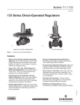
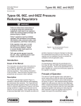
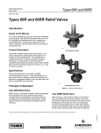
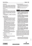
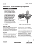
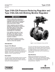
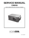
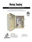
133 Series
Instruction Manual
Form 5007
June 2013
133 Series Direct-Operated Regulators
Table of Contents
Introduction...................................................................1
Specifications...............................................................2
Principle of Operation...................................................2
Installation.....................................................................3
Overpressure Protection..............................................4
Startup..........................................................................4
Adjustment....................................................................5
Shutdown......................................................................6
Maintenance.................................................................6
W1327
TYPES 133H, 133L, AND 133Z REGULATORS
Parts Ordering.............................................................11
Parts List.................................................................... 11
W6803
TYPE 133HP REGULATOR
!
WARNING
Figure 1. 133 Series Gas Regulators
Failure to follow these instructions or
to properly install and maintain this
equipment could result in an explosion
and/or fi re causing property damage and personal injury or death.
Fisher® regulators must be installed,
operated, and maintained in accordance
with federal, state, and local codes,
rules and regulations, and Emerson
Process Management Regulator
Technologies, Inc. (Regulator
Technologies) instructions.
If the regulator vents gas or a leak
develops in the system, service to the unit
may be required. Failure to correct trouble
could result in a hazardous condition.
Scope of the Manual
This manual provides specifications, installation,
adjustment and maintenance instructions, and parts
ordering information for the 133 Series regulators.
Only personnel qualified through training or experience
should install, operate, and maintain this regulator. If
there are any questions concerning these instructions,
contact your local Sales Office before proceeding.
Product Description
The 133 Series direct-operated gas regulators, shown
in Figure 1 are primarily designed for industrial and
commercial applications supplying gas to furnaces,
burners, and other appliances. The 133 Series
D100270X012
Call a gas service person to service the
unit. Only a qualifi ed person must install or service the regulator.
Introduction
www.fisherregulators.com
133 Series
Specifications
The Specifications section lists the specifications for the Type 133 Series direct-operated regulators. Factory
specification is stamped on the nameplate fastened on the regulator at the factory.
Available Constructions
Type 133H:
High pressure construction for outlet pressure
range of 1.5 to 10 psig / 0.10 to 0.69 bar. The
Type 133H can also use the 2 inches w.c.
to 2 psig / 5 mbar to 0.14 bar springs of the
Type 133L. The maximum operating inlet
pressure is 60 psig / 4.1 bar with a maximum
emergency inlet pressure of 125 psig / 8.6 bar.
Type 133HP:
Extra high pressure construction for outlet
pressure range of 2 to 60 psig / 0.14 to 4.1 bar.
The maximum operating and emergency inlet
pressure rating is 150 psig / 10.3 bar.
Type 133L:
Low pressure construction for outlet pressure
range of 2 inches w.c. to 2 psig / 5 mbar to
0.14 bar. The maximum operating inlet pressure is
60 psig / 4.1 bar with a maximum emergency inlet
pressure of 125 psig / 8.6 bar.
Type 133Z:
Zero governor construction for outlet pressure
range of -1 to 4 inches w.c. / -2 to 10 mbar. The
maximum operating inlet pressure is 20 psig /
1.4 bar with a maximum emergency inlet pressure
of 125 psig / 8.6 bar.
Body Size and End Connection Styles
BODY SIZE
BODY MATERIAL
INCH
DN
Cast Iron Body
WCC Steel Body
2
50
NPT or CL125 FF Flanged
NPT or CL150 RF Flanged
Outlet Pressure Ranges
See Table 1
Maximum Inlet Pressures(1)
See Table 2
Maximum Outlet Pressures
See Table 2
Pressure Registration
External; downstream control line is required.
Temperature Capabilities(1)
-20 to 150°F / -29 to 66°C
Control Line Connection
Types 133H, 133L, and 133Z:
3/4 NPT (internal); connection will be positioned
directly over body outlet (standard position)
or 90 degrees right or left of standard position
if specified.
Type 133HP:
1/4 NPT (internal) connection positioned directly
over body outlet.
Vent Connection
Types 133H, 133L, and 133Z:
1 NPT (internal) with screen; standard position is in
line with control line connection directly over body
outlet. Vent will always be positioned over the
control line connection.
Type 133HP:
1/2 NPT (internal) connection positioned directly
over body inlet with a Fisher® Type Y602-7
vent assembly.
Approximate Weight
Types 133H, 133L, and 133Z NPT End
Connections: 35 pounds / 16 kg
Types 133H, 133L, and 133Z Flanged End
Connections: 40 pounds / 18 kg
Type 133HP NPT End Connections:
56.5 pounds / 26 kg
Type 133HP Flanged End Connections:
62.5 pounds / 28 kg
1. The pressure/temperature limits in this Instruction Manual or any applicable standard limitation should not be exceeded.
balancing system enables the regulator to provide
accurate control gas pressure for maximum combustion
efficiency despite varying inlet pressure conditions. The
single port construction provides bubble-tight shutoff.
An external downstream control line is required for
the operation of the regulator. A restriction collar is
available to reduce the flow capacity of the regulator.
2
Principle of Operation
Refer to the operational schematics in Figures 2 and 3.
In the 133 Series, downstream pressure is registered
under the diaphragm via the external control line and
is used as the operating medium. Increased demand
lowers the downstream pressure and allows the spring
to move the diaphragm and stem assembly down,
opening the valve disk, and supplying more gas to the
133 Series
CONTROL SPRING
DIAPHRAGM
DOWNSTREAM
CONTROL LINE
BALANCING
DIAPHRAGM
STEM
ORIFICE
INLET PRESSURE
OUTLET PRESSURE
ATMOSPHERIC PRESSURE
BOOST PRESSURE
A6555
INLET
INLETPRESSURE
PRESSURE
OUTLET
PRESSURE
OUTLET
PRESSURE
ATMOSPHERIC
PRESSURE
ATMOSPHERIC
PRESSURE
BOOST
PRESSURE
BOOST
PRESSURE
VALVE DISK
REGISTRATION DISK
Figure 2. Operational Schematic of Type 133L Regulator (Also Typical of Type 133H)
downstream system. Decreased demand increases
the downstream pressure and moves the diaphragm
and stem assembly up, closing the valve disk, and
decreasing the gas supply to the downstream system.
Boosting System
The 133 Series incorporates a balancing diaphragm
and a boosting system. When the regulator is locked
up, inlet pressure is registered on the top of the valve
disk and on the bottom of the balancing diaphragm
through registration holes in the top of the cage. Also,
downstream pressure is registered on the bottom
of the valve disk and on the top of the balancing
diaphragm through a passage formed by grooves in
the registration disk and an annular space between the
stem and stem sleeve.
When the valve disk is open, gas flows from the inlet
over the edge of the valve disk to the outlet. Under
the valve disk near the registration disk, there is little
gas flow. The gas pressure near the registration disk
is higher than it is in the flow path where gas velocity
tends to lower the pressure. The higher pressure
near the disk is registered on the top of the balancing
diaphragm through the registration disk and the
annular space between the stem and stem sleeve.
This pressure registered on the top of the balancing
diaphragm aids downward disk travel and
compensates for spring and diaphragm effect. This
improves regulator range ability and performance.
Installation
Before installing the 133 Series regulators, inspect it
for shipping damage and be certain that the body and
orifice are clean. Blow out the pipeline to remove pipe
scale and other foreign material.
The regulator may be installed in any position as long
as the flow through the body is the same as indicated
by the flow direction arrow on the body and the vent
opening is unobstructed and protected from the
entrance of rain, ice, and other foreign material.
3
ESSURE
PRESSURE
HERIC PRESSURE
PRESSURE
DIATE PRESSURE
PPLY PRESSURE
PRESSURE
ESSURE
RESSURE
RESSURE
RESSURE
SSURE
ESSURE
RIC PRESSURE
ESSURE
Type 133HP
Without the control line, the regulator will remain wideopen. The downstream control line should be a pipe of
at least 1/2 inch / 12.7 mm diameter; connect it to the
downstream pipe line at least 5 to 10 pipe diameters
from the regulator and in a straight section of pipe.
The external downstream control line connection on
the Type 133HP is 1/4 NPT.
VENT
ASSEMBLY
Vent
DIAPHRAGM
DOWNSTREAM
CONTROL LINE
A6883
INLET PRESSURE
OUTLET PRESSURE
ATMOSPHERIC PRESSURE
BOOST PRESSURE
Figure 3. Operational Schematic of Type 133HP
If the regulator has threaded end connections, coat
external threads with pipe compound. For flanged
end connections, tighten the flange bolts evenly.
Install a three valve bypass around the 133 Series if
continuous operation is necessary.
The regulator must be protected from damage by
vehicles and other outside sources.
Overpressure Protection
The 133 Series regulators have an outlet pressure
rating that is lower than the inlet pressure rating. Some
type of overpressure protection is needed if the actual
inlet pressure exceeds the outlet pressure rating.
Maximum operating inlet pressure for the 133 Series
regulators is given in Table 2. All models must
be protected against inlet pressure above their
listed maximum.
Regulator operation below these emergency pressure
limitations does not preclude the possibility of damage
from external sources or from debris in the gas line.
The regulator should be inspected for damage after any
overpressure condition.
Downstream Control Line
An external downstream control line must be installed
before putting the 133 Series regulators in operation.
4
The 133 Series vent is screened to prevent insects
or foreign material from entering. The Types 133H,
133L, and 133Z regulators have a 1 NPT (internal)
connection and the Type 133HP has a 1/2 NPT
internal connection. If a vent to the atmosphere is
required for indoor installations, do the following:
• For Types 133H, 133L, and 133Z — remove the
snap ring and screen (keys 8J and 8H, Figure 10,
11, or 12) and pipe the vent to the outside.
A6883
33HP
133 Series
• For Type 133HP — remove the Type Y602-7
screened vent assembly and pipe nipple (keys 50
and 49, Figure 14) from the spring case (key 8)
and pipe the vent to the outside.
The vent pipe should be as short as possible with
minimum number of bends or elbows. The pipe should
also have the largest practical diameter. Install a
weather and bug resistant vent assembly on the outside
end of the vent pipe.
For indoor installation that have been piped to the
outside and for outdoor installations, the vent opening
must be positioned so that water, ice, and other foreign
material cannot enter the spring case. Use care not to
place the vent opening below downspouts and eaves.
The vent opening should be checked periodically to be
sure that the opening has not been plugged with foreign
material. On some installations it may be necessary to
provide additional protection from the elements.
Startup
!
WARNING
If the downstream system is already
pressured by another regulator or by a
manual bypass, then extra precautions
must be taken when placing the 133 Series
in service. The outlet of the regulator
must never be subjected to pressure
higher than the inlet pressure, or the
balancing diaphragm may be damaged.
133 Series
Table 1. 133 Series Outlet Pressure Ranges, Control Springs
CONTROL SPRINGS
OUTLET PRESSURE RANGE
TYPE
Part Number
Color Code
0.10 to 0.21
0.14 to 0.34
0.34 to 0.69
1H975927032
10A9440X012
1J146927142
133HP(1)
2 to 5
4.5 to 10
6 to 20
16 to 30
26 to 40
36 to 50
45 to 60
0.14 to 0.34
0.31 to 0.69
0.41 to 1.4
1.1 to 2.1
1.8 to 2.8
2.5 to 3.4
3.1 to 4.1
133L(1) and 133H(2)
2 to 4 inches w.c.
3.5 to 6 inches w.c.
5 to 9 inches w.c.
8.5 to 18 inches w.c.
14 to 28 inches w.c.
0.75 to 2
-1 to 1 inch w.c.
Wire Diameter
mm
Inch
mm
Orange
Yellow
Blue
6.91
6.47
6.19
176
164
157
0.250
0.283
0.375
6.35
7.19
9.52
17B8632X012
17B8633X012
10C1238X012
10C1240X012
10C1241X012
10C1242X012
10C1243X012
Yellow
Orange
Silver
Red
Blue
Green
White
8.50
8.50
8.25
8.25
8.25
8.25
8.25
216
216
210
210
210
210
210
0.282
0.343
0.375
0.438
0.500
0.500
0.531
7.16
8.71
9.53
11.1
12.7
12.7
13.5
5 to 10 mbar
9 to 15 mbar
12 to 22 mbar
21 to 45 mbar
35 to 70 mbar
0.05 to 0.14
1D892527022
1D892627022
1D892727012
1D893227032
1D893327032
1H975827032
Brown
Red
Black
White
Green
Blue
6.13
7.53
7.88
7.50
7.25
7.09
156
191
200
190
184
180
0.109
0.112
0.130
0.156
0.182
0.225
2.77
2.85
3.30
3.96
4.62
5.72
-3 to 3 mbar
1K633427012
(Extension Spring)
Unpainted
2.00
50.8
0.075
1.91
Unpainted
2.00
50.8
0.075
1.91
0 to 10 mbar
1K633427012
(Extension Spring)
and
1D892527022
(Compression Spring)
Brown
6.13
156
0.109
2.77
bar
133H(1)
1.5 to 3
2 to 5
5 to 10
133Z(1)
0 to 4 inches w.c.
Free Length
Inch
psig
1. P
ressure ranges shown are correct if the regulator is installed with the actuator portion above the body portion. If the regulator is installed with the actuator portion below the body, the
pressure ranges will be lowered by approximately 2 inches w.c. / 5 mbar for the Type 133L and by approximately 3 inches w.c. / 7 mbar for the Types 133H and 133Z.
2. If the 2 inches w.c. / 5 mbar to 2 psig / 0.14 bar springs (all 6 ranges) are used in the Type 133H, the pressure ranges will increase by approximately 1 inch w.c. / 2 mbar due to the
weight of the Type 133H parts (assuming that the actuator is installed above the body).
Table 2. Maximum Inlet and Outlet Pressures
TYPE NUMBER
PRESSURES
133H
133HP
psig
bar
Maximum Operating Inlet Pressure
60
4.1
Maximum Emergency Inlet Pressure
125
8.6
Maximum Operating Outlet Pressure(1)
10
0.69
Maximum Outlet Pressure Over
Outlet Pressure Setting
3
0.21
Maximum Emergency Outlet
(Casing) Pressure
15
1.0
psig
150
133L
bar
10.5
Setpoint
plus 40
Setpoint
plus 2.8
150
10.5
133Z
psig
bar
psig
bar
60
4.1
20
1.4
125
8.6
125
8.6
2
0.14
4 inches
w.c.
10 mbar
3
0.21
3
0.21
15
1.0
15
1.0
1. With highest spring range available only.
Also, the control line pressure must never
exceed the set point dictated by the spring
setting by more than 3 psig / 0.21 bar, or
the valve seat or diaphragm plates can be
damaged. The procedure used in putting
the regulator in service must be planned
accordingly. Pressure gauges should
always be used to monitor downstream
and control line pressures during startup.
If the downstream system is not pressured by
another regulator or by manual bypass, use the
following procedure:
1. Check to see that all appliances are turned off.
2. Slowly open the upstream shutoff valve.
3. Slowly open the downstream shutoff valve.
4. Check all connections for leaks.
5. Make final control spring adjustments according to
the adjustment procedures.
Adjustment
To increase the pressure setting, remove the closing
cap (key 9, Figures 10, 11, 12, and 14) and turn
the adjusting screw (key 11) clockwise; to lower the
setting, turn the adjusting screw counterclockwise.
A pressure gauge should always be used when
adjustments are being made. Do not adjust the spring
to produce an outlet pressure setting above the limit
5
133 Series
stamped on the nameplate (key 38, not shown),
located on the casing flange. If the required pressure
setting is not within the range of the spring in use,
substitute with the correct spring. Ranges of available
springs are shown in Table 1. When changing the
spring, also change the nameplate, located on the
casing flange, to indicate the outlet pressure range.
Shutdown
Isolate the regulator from the pressure system and
release pressure from the outlet and the control line.
Inlet pressure will then automatically be released as
the regulator opens up in response to the lowered
pressure on the diaphragm.
Maintenance
This section includes instructions for disassembly
and replacement of parts. All key numbers refer to
Figures 10, 11, 12, and 14, except where indicated.
!
WARNING
To avoid personal injury, property
damage, or equipment damage caused
by sudden release of pressure or
explosion of accumulated gas, do not
attempt any maintenance or disassembly
without fi rst isolating the regulator from system pressure and relieving all internal
pressure from the equipment.
Do not loosen the diaphragm casing cap
screws (keys 35 and 36) when the control
spring (key 12) has spring force applied
to it. Release the spring compression as
described in step 7.
Due to normal wear that may occur in gas regulators,
parts must be periodically inspected and replaced if
necessary. The frequency of inspection, maintenance,
and replacement of parts depend upon the severity of
service conditions or requirements of local, state, and
federal regulations.
Types 133H, 133L, and 133Z
Disassembly
1. Disconnect the downstream control line from the
regulator and disconnect the remote vent pipe if
one is used.
6
W1390/IL
Figure 4. Spring Case Inserted in Body for Disassembly. Note
Proper Method of Holding Stem and Sleeve When Loosening or
Tightening Stem Nut.
Note
Allowing a slight amount of compression
to remain in the regulator spring (key 12)
will facilitate disassembly of the trim parts.
2. Unscrew the four locknuts (key 34) and lift the
actuator portion off the body (key 1). All of the trim
parts will come out of the body with the actuator.
Inspect the valve disk (key 28), orifice (key 2), and
restriction collar (key 46, Figure 13), if used.
3. For further field disassembly and inspection, the
actuator may be turned upside down and the
spring case (key 8A) inserted into the body cavity
(see Figure 4).
CAUTION
Use care in performing step 4 to guard
against damage to the balancing
diaphragm (key 22).
4. Insert a 1/2-inch / 13 mm open-end wrench
between the legs of the cage (key 5) and place
the wrench on the stem sleeve wrench flats. Hold
this wrench while unscrewing the nut (key 31) to
prevent stem and stem sleeve (keys 18 and 25)
133 Series
W1371/IL
W1372/IL
Figure 5. Inspecting Guide Bushing and Stem Seal O-ring
Figure 6. Installing Balancing Diaphragm. The Side of
Diaphragm Marked Piston Side Must Face Casing.
rotation and diaphragm (key 15) and balancing
diaphragm (key 22) damage due to twisting
(see Figure 4).
7. To inspect or replace the upper stem seal O-ring
(key 19) or main diaphragm (key 15) on the
Type 133L or 133H (Figure 10 or 11), remove the
closing cap (key 9), and inspect the closing cap
gasket (key 10). Release spring compression
by slowly turning the adjusting screw (key 11)
counterclockwise and remove the spring (key 12).
5. Remove the washer, registration disk, and valve
disk (keys 30, 29, and 28). To remove the restriction
collar (key 46, Figure 13) (if used), loosen the
set screw (key 47, Figure 13) and slip the E-ring
(key 26, Figure 13) and collar off of the stem
(key 18). Remove the orifice (key 2) by rotating it
until the pins (key 5A) in the cage line up with the
slots in the orifice; then, lift off the orifice. Replace
the valve disk and orifice if necessary.
6. Loosen the set screws (key 39) in the cage (key 5)
and remove the roll pin (key 27) from the stem
(key 18). Remove the cage and stem sleeve
(key 25), the sealing washer (key 17) under
the balancing diaphragm (key 22), flat washers
(key 23), balancing diaphragm, and balancing
diaphragm plate (key 21). Replace sealing washer
and balancing diaphragm if necessary.
!
WARNING
To avoid personal injury due to the
sudden uncontrolled movement of parts,
do not loosen the diaphragm casing
cap screws (keys 35 and 36) when the
control spring (key 12) has spring force
applied to it.
For Type 133Z (Figure 12), remove the closing cap
(key 9) and inspect the closing cap gasket (key 10).
Release any spring compression by slowly turning
the adjusting screw (key 11) counterclockwise. Lift
the adjusting screw assembly (keys 11, 41, 42, 43,
and 45) out of the spring case with pliers. Unhook
the extension spring (key 44) from the spring
retainer (key 42). Remove the compression spring
(key 12) if one is used.
8. Unscrew the cap screws and nuts (keys 35 and 36)
and remove the spring case (key 8A).
9. Pull out the diaphragm and stem as assembly;
replace diaphragm (key 15) and sealing washer
(key 17) if necessary. When removing or replacing
the diaphragm, clamp the smallest diameter portion
of the stem in a vise while turning the nut (key 20).
10. If necessary, replace the bearing (key 6) and the
upper stem seal O-ring (key 19, Figure 5). Before
reassembling, coat the O-ring with O-ring sealant
and lubricant.
Release the spring compression as
described in step 7.
7
133 Series
Reassembly
Type 133HP
Reassemble in reverse order of the above steps. When
reassembling, observe the following steps and cautions.
Disassembly
1. If the spring case was disassembled, reassemble
it first. To ensure proper slack in the diaphragm
(key 15) and to facilitate reassembly of the trim
parts, tighten the casing cap screws and nuts
(keys 35 and 36) finger-tight only. Then adjust the
spring (key 12) to stroke the diaphragm assembly
fully. Final tightening of the casing cap screws and
nuts must be done alternately in equal increments
to ensure a proper seal without crushing
the diaphragm.
2. During reassembly, check all O-rings to be certain
they are in good condition; replace if necessary.
Lubricate the O-rings (keys 4, 19, and 32) with
elastomer sealant and lubricant. Apply anti-seize
compound liberally to the adjusting screw threads
(key 11), as indicated in Figures 10 to 12.
3. When installing the balancing diaphragm (key 22),
be certain the side marked PISTON SIDE is facing
the spring case. Carefully tuck the slack diaphragm
material into the space between the diaphragm
plate (key 21) and the lower casing (key 7) until the
diaphragm fits smoothly over the diaphragm plate
without wrinkles and the bead fits snugly and evenly
in the groove provided in the lower casing. This can
be done with a small screwdriver, but be careful not
to puncture the diaphragm (see Figure 6).
4. When replacing the cage (key 5), insert the set
screws (key 39) only far enough to retain the cage.
Do not tighten.
5. The registration disk (key 29) is marked for
proper placement; be certain it is positioned
correctly on the stem (key 18).
CAUTION
Always use the stem sleeve wrench
flats when loosening or tightening the
nuts (key 20 or 31) to prevent twisting
of the main and balancing diaphragms
(keys 15 and 22).
6. Be certain the Belleville spring washer (key 3) is in
good condition and is in place before placing the
actuator on the body (key 1).
8
!
WARNING
To avoid personal injury, property
damage, or equipment damage caused
by sudden release of pressure or
explosion of accumulated gas, do not
attempt any maintenance or disassembly
without first isolating the regulator from
system pressure and relieving all internal
pressure from the equipment.
Do not loosen the diaphragm casing cap
screws (Figure 9, keys 35 and 36) when
the control spring (key 12) has spring
force applied to it. Release the spring
compression as described in step 6.
This section includes instructions for disassembly
and replacement of parts for the Type 133HP. All
key numbers refer to Figures 7, 8, 9, and 14, except
where indicated.
1. Disconnect the downstream control line from the
regulator and disconnect the remote vent pipe if
one is used.
2. Unscrew the four locknuts (key 34) and lift the
actuator portion off the body (key 1). All of the trim
parts will come out of the body with the actuator.
Inspect the valve disk (key 28), orifice (key 2), and
restriction collar (key 46), if used.
CAUTION
Use care in performing step 3 to guard
against damage to the balancing
diaphragm (key 22).
3. Insert a 1/2-inch / 13 mm open-end wrench
between the legs of the cage (key 5) and place
the wrench on the stem sleeve wrench flats. Hold
this wrench while unscrewing the nut (key 31) to
prevent stem and stem sleeve (keys 18 and 25)
rotation and diaphragm (key 15) and balancing
diaphragm (key 22) damage due to twisting.
4. Remove the washer, registration disk, and
valve disk (keys 30, 29, and 28). To remove the
restriction collar (key 46, Figure 13) (if used),
loosen the set screw (key 47, Figure 13) and
slip the E-ring (key 26, Figure 13) and collar off
133 Series
18
20
58
15
13
14
61
16
PROTECT THE
O-RING
SURFACE
FROM DAMAGE
3/4-inch / 19 mm
STEM HEX
A7007
Figure 7. Stem and Diaphragm Assembly
the stem (key 18). Lift off the orifice (key 2) and
replace the valve disk and orifice if necessary.
5. Loosen the set screws (key 39) in the cage (key 5)
and remove the roll pin (key 27) from the stem
(key 18). Remove the cage and stem sleeve
(key 25), the sealing washer (key 17) under
the balancing diaphragm (key 22), flat washers
(key 23), balancing diaphragm, and balancing
diaphragm plate (key 21). Replace the sealing
washer and balancing diaphragm if necessary.
!
WARNING
the diaphragm casing cap screws and hex nuts
(keys 35 and 36), and lift off the upper diaphragm
casing (key 52). Remove the cap screws (key 55)
and mounting bracket (key 56). Inspect the two
mounting bracket gaskets (key 57) and replace
if necessary.
8. Remove the hex nut (key 20), lock washer (key 58),
and spring seat (key 13) from the stem (key 18).
9. Remove the diaphragm plate (key 14), diaphragm
(key 15), diaphragm washer O-ring (key 61),
and sealing diaphragm plate (key 16). Replace
the diaphragm and diaphragm washer O-ring
if necessary.
• To avoid personal injury due to the sudden uncontrolled movement of
parts, do not loosen the diaphragm
casing cap screws (keys 35 and 36)
when the control spring (key 12) has
spring force applied to it.
10. Remove the cap screws (key 53) and lift the
lower diaphragm casing (key 7) off the casing
adaptor (key 60). If necessary, replace the
bearing (key 6) and upper stem seal O-ring
(key 19). Before reassembling, coat the O-ring
with a O-ring sealant and lubricant.
• Release the spring compression as described in step 6 below.
Reassembly
6. To inspect or replace the upper stem seal O-ring
(key 19) or main diaphragm (key 15), remove the
closing cap (key 9), and inspect the closing cap
gasket (key 10). Release the spring compression
completely by loosening the hex nut (key 59) and
turning the adjusting screw (key 11) counterclockwise.
When reassembling, observe the following steps and
cautions. During reassembly, check all O-rings to
be certain they are in good condition and replace if
necessary. Coat O-rings (keys 4, 19, and 32) with
Multi-Purpose Polytetrafluoroethylene (PTFE) lubricant
or an equivalent elastomer sealant and lubricant.
7. Remove the six cap screws (key 62) from the
spring case (key 8). Lift off the spring case, upper
spring seat (key 41), and spring (key 12). Remove
All key numbers refer to Figures 7, 8, 9, and 14,
except where indicated.
9
133 Series
APPLY PTFE SEALANT TO THREADS
AND INSTALL WITH CONTROL LINE
CONNECTION POINTING AWAY FROM
THE CASING ADAPTOR
53
7
6
19
54
60
1/4 NPT CONTROL LINE
CONNECTION
51
32
39
A7008/IL
Figure 8. Lower Casing and Casing Adaptor Assembly
55
56
57
WHEN ASSEMBLING THE ACTUATOR,
THE UPPER CASING AND ADAPTOR
SHOULD BE POSITIONED SO THAT TWO
HOLES IN THE 5.25-inch / 133 mm BOLT
HOLE CIRCLE ARE EQUALLY SPACED
OVER THE CONTROL CONNECTION
52
35
36
18
A7009/IL
Figure 9. Diaphragm Casing Assembly
1. With the Type 133HP completely disassembled,
start the reassembly by applying Multi-Purpose
PTFE lubricant or an equivalent to the stem threads
(key 18) and diaphragm washer O-ring (key 61).
Place the sealing diaphragm plate (key 16) on the
stem followed by the O-ring (key 61), diaphragm
(key 15), diaphragm plate (key 14), spring seat
(key 13), lock washer (key 58), and hex nut
(key 20) as shown in Figure 7. To prevent diaphragm
damage, torque the hex nut (key 20) to 25 to
30 foot-pounds / 34 to 41 N•m, while using 3/4-inch /
19 mm wrench flats on the stem.
2. If the street elbow (key 51) was removed, it
must be reassembled before mounting the
casing adaptor (key 60). Apply PTFE sealant
or equivalent around the external threads of
the street elbow and tighten to a torque of 20 to
35 foot-pounds / 27 to 47 N•m. Position the
10
control line connection (street elbow) so that it
points away from the casing adaptor.
3. Lubricate the O-rings (keys 19, 32, and 54) and
install as shown in Figure 8. Install the casing
adaptor (key 60) to the lower casing (key 7)
and tighten the cap screws (key 53) to 20 to
30 foot-pounds / 27 to 41 N•m of torque.
4. Insert the stem bearing (key 6) and carefully insert
the stem (key 18) into the lower casing (key 7) and
casing adaptor (key 60) assembly.
5. Assemble the upper diaphragm casing (key 52),
mounting plate adaptor (key 56), and mounting
plate gasket (key 57) as shown in Figure 9.
Tighten the cap screws (key 55) to 20 to
30 foot-pounds / 27 to 41 N•m of torque.
6. Assemble the upper and lower casings, noting that
two of the holes in the 5-1/4-inch / 133 mm diameter
133 Series
bolt circle in the mounting plate adaptor (key 56)
must be spaced (aligned) an equal distance over
the downstream control line connection. Install cap
screws and hex nuts (keys 35 and 36) with a torque
of 20 to 30 foot-pounds / 27 to 41 N•m.
7. Place the balancing plate washer (key 23),
balancing diaphragm plate (key 21), balancing
diaphragm (key 22) and a second balancing plate
washer (key 23), onto the stem (key 18).
Note
12. Install the valve disk (key 28), registration disk
(key 29), washer (key 30) and hex nut (key 31)
onto the stem. The registration disk (key 29)
is marked for proper placement; be certain it
is positioned correctly on the stem (key 18).
Tighten the hex nut (key 31) using the 1/2-inch /
13 mm wrench flats on the stem sleeve.
13. Insert the valve trim assembly into the body
and position the downstream control line
connection (key 51) so it is pointing directly
over the body outlet.
When installing the balancing diaphragm
(key 22), be certain the side marked
PISTON SIDE is facing the spring case.
Carefully tuck the slack diaphragm
material into the space between the
diaphragm plate (key 21) and lower
casing (key 7) until the diaphragm
fits smoothly over the diaphragm
plate without wrinkles and the bead
fits snugly and evenly in the groove
provided in the lower casing. This can
be done with a small screw screwdriver,
but be careful not to puncture the
diaphragm (see Figure 6).
14.Screw the studs (key 33) into the body (key 1).
Install and tighten the hex nuts (key 34) to
20 to 35 foot-pounds / 27 to 47 N•m of torque.
8. Apply Multi-Purpose PTFE lubricant or equivalent
to the sealing washer (key 17) and carefully slide
over the threaded end of the stem (key 18).
17. Screw in the pipe nipple (key 49) and vent
(key 50). Install the closing cap gasket (key 10)
and closing cap (key 9).
9. Insert the guide bushing (key 24) into the cage
(key 5), and slide the cage up onto the stem
(key 18). Insert the set screws (key 39) only far
enough to retain the cage. Do not tighten.
Parts Ordering
10. Lubricate and install the O-rings (keys 19 and 4)
as indicated in Figure 14. Install the orifice (key 2)
onto the cage (key 5). Install the Belleville spring
washer (key 3) so that the concave face of the
washer faces away from the orifice.
11. Install the E-ring (key 26) on the stem sleeve
(key 25) and slide the stem sleeve over the stem
(key 18) aligning the slotted end of the stem sleeve
so that the roll pin (key 27) can be inserted through
the cross-drilled hole in the end of the stem.
CAUTION
Always use the stem sleeve wrench
flats when loosening or tightening the
nuts (key 20 or 31) to prevent twisting
of the main and balancing diaphragms
(keys 15 and 22).
15. Apply anti-seize to the adjusting screw (key 11)
and upper spring seat (key 41). Install the
adjusting screw and hex jam nut (key 59) into the
spring case (key 8). Position the control spring
(key 12) and upper spring seat on the diaphragm
plate (key 14) and lower spring seat (key 13).
16. Install the mounting plate gasket (key 57) and
place the spring case on the mounting bracket
(key 56). Install the cap screws (key 62) and
torque to 20 to 30 foot-pounds / 27 to 41 N•m.
When corresponding with your local Sales Office about
this equipment, be sure to include the type number and
other information stamped on the nameplate.
When ordering replacement parts, reference the key
number of each needed part and specify the eleven
character part number as found in the following parts list.
Parts List
Key Description
Parts kit for Types 133H, 133L, and 133Z
(included are keys 2, 4, 6, 10, 15, 17, 19, 22,
24, 28, 32, and 40)
1 Body
Cast iron
2 NPT NPS 2 / DN 50, CL125 FF
WCC Steel
2 NPT NPS 2 / DN 50, CL150 RF
Part Number
R133HX00012
30A3044X012
30A3045X012
30B0855X012
30B0854X012
11
133 Series
10
12
17
16
18
23
25
36
2
9
8A
11
14
20
8G
13
8D
6
8E
21
8J
35
15
22
32
39
7
3
5A
4
19
8F
8B
8C
8H
33
34
24
5
1
26
28
19
29
27
31
30
40A3066
APPLY LUBRICANT (L) OR SEALANT (S)(1)
1. Lubricant and sealant must be selected such that they meet the temperature requirements.
Figure 10. Type 133L Assembly
Key Description
2* Orifice, Aluminum
3
Belleville Spring Washer, 17-4PH Stainless steel
4* O-ring
Nitrile (NBR)
Fluorocarbon (FKM)
(for Types 133L and 133H only)
5* Cage/Pin Assembly, Aluminum/Steel
(including roll pins, key 5A)
6* Bearing, Nylon (PA)
7
Lower Casing
Types 133H, 133L, and 133Z, Aluminum
Type 133HP, Steel
8 Spring Case
Type 133HP, Cast iron
Parts 8A through 8J are used on
Types 133H, 133L, and 133Z only
8A Spring Case, Aluminum
8B Stabilizer Stem, 302 Stainless steel
8C Lower Stabilizer, Nylon (PA)
8D Upper Stabilizer, Polyethylene
8E Orifice, Stainless steel
8F Screw, Steel (3 required)
8G Spring, 302 Stainless steel (2 required)
8H Screen, Stainless steel
8J Snap Ring, 302 Stainless steel
9
Closing Cap
Types 133H, 133L, and 133Z, Aluminum
Type 133HP, Cast iron
10* Closing Cap Gasket
Types 133H, 133L, and 133Z, Neoprene (CR)
Type 133HP, Composition
Part Number
20A3046X012
10A3047X012
10A9339X012
10A9339X022
20A3048X012
10A3049X012
40A3050X012
32B3499X012
2H140619012
4L142308032
1H976335022
1H976406992
1H976506992
T13609T0012
1H976728982
1H976837022
1E564843122
1E564937022
1L928308012
00288819012
1N446206992
1R742604022
Key Description
Part Number
11 Adjusting Screw
Type 133H, Brass
1V9069X0012
Type 133L, Aluminum
1L928608012
Type 133Z, Brass
1K633714012
Type 133HP, Steel
1H139731012
12 Spring Steel
Type 133H
Zinc-plated steel
1.5 to 3 psig / 0.10 to 0.21 bar, Orange 1H975927032
2 to 5 psig / 0.14 to 0.34 bar, Yellow 10A9440X012
17-7 PH Stainless steel
5 to 10 psig / 0.34 to 0.69, Blue 1J146927142
Types 133L and 133H(1)
Zinc-plated steel
2 to 4 inches w.c. / 5 to 10 mbar, Brown 1D892527022
3.5 to 6 inches w.c. / 9 to 15 mbar, Red 1D892627022
Plated steel
5 to 9 inches w.c. / 12 to 22 mbar, Black 1D892727012
8.5 to 18 inches w.c. / 21 to 45 mbar, White 1D893227032
14 to 28 inches w.c. / 35 to 70 mbar, Green 1D893327032
0.75 to 2 psig / 0.05 to 0.14 bar, Blue 1H975827032
Type 133Z (Extension spring, key 44, also required)
Zinc-plated steel
-1 to 1 inch w.c. / -2 to 2 mbar, see key 44
0 to 4 inches w.c. / 0 to 10 mbar, Brown 1D892527022
Type 133HP
17-7 PH Stainless steel
2 to 5 psig / 0.14 to 0.34 bar, Yellow 17B8632X012
302 Stainless steel
4.5 to 10 psig / 0.31 to 0.69 bar, Orange 17B8633X012
* Recommended spare parts.
1. If the 2 inches w.c. to 2 psig / 5 mbar to 0.14 bar springs listed under Type 133L are used in the Type 133H, the pressure ranges will increase by approximately 1 inch w.c. / 2 mbar due to
the weight of the Type 133H parts (assuming that the actuator is installed above the body).
12
133 Series
10
12
17
16
18
23
25
36
2
40A3070
9
8A
11
14
20
8G
13
8D
6
8E
21
8J
35
15
22
32
39
7
3
5A
4
26
28
19
29
27
31
40
19
8F
8B
8C
8H
33
34
24
5
1
30
APPLY LUBRICANT (L) OR SEALANT (S)
1. Lubricant and sealant must be selected such that they meet the temperature requirements.
(1)
Figure 11. Type 133H Assembly
Key Description
12
Spring Steel (continued)
Type 133HP (continued)
Steel
6 to 20 psig / 0.41 to 1.4 bar, Silver 16 to 30 psig / 1.1 to 2.1 bar, Red
26 to 40 psig / 1.8 to 2.8 bar, Blue 36 to 50 psig / 2.5 to 3.5 bar, Green 45 to 60 psig / 3.1 to 4.1 bar, White 13 Spring Seat, Plated steel
Types 133H, 133L, and 133Z
Type 133HP
14 Diaphragm Plate, Steel
Type 133H (1 required)
Type 133L (1 required)
Type 133Z (2 required)
Type 133HP (1 required)
15* Diaphragm, Nitrile (NBR) and Nylon (PA)
Types 133H, 133L, and 133Z
Type 133HP Fluorocarbon (FKM)
(for Types 133L and 133H only)
16 Sealing Diaphragm Plate, Zinc-plated steel
Types 133H, 133L, and 133Z
Type 133HP
17* Sealing Washer, Zinc-plated steel
(2 required for Types 133L, 133H, and 133Z;
1 required for Type 133HP)
18 Stem, Stainless steel
Types 133H and 133L
Type 133Z
Type 133HP
Part Number
10C1238X012
10C1240X012
10C1241X012
10C1242X012
10C1243X012
10A3052X012
1P787724152
1D555725012
1J881725072
1J881725072
22B3514X012
1N150802052
22B3514X012
1N150802402
1D475725062
12B3517X012
1F990428982
20A3053X012
10A3069X012
37B3942X012
Key Description
19* O-ring
Nitrile (NBR)
(2 required for Types 133L, 133H,
and 133HP; 1 required for Type 133Z)
Fluorocarbon (FKM)
(2 required for Types 133L and 133H only)
20 Hex Nut
Types 133H, 133L, and 133Z, Aluminum
Type 133HP, Zinc-plated steel
21 Diaphragm Plate, Plated steel
22* Diaphragm
Nitrile (NBR) and Nylon (PA)
Fluorocarbon (FKM)
(for Types 133L and 133H only)
23 Washer, Steel (2 required)
24* Guide Bushing, Nylon (PA)
25 Stem Sleeve, 303 Stainless steel
26 E-ring, Plated steel
27 Roll Pin, 420 Stainless steel
28* Valve Disk Assembly
Aluminum / Neoprene (CR)
Aluminum / Fluorocarbon (FKM)
(for Types 133L and 133H only)
29 Registration Disk, Nylon (PA)
30 Washer, Zinc-plated steel
31 Hex Nut, Zinc-plated steel
32* O-ring
Nitrile (NBR)
Fluorocarbon (FKM)
(for Types 133L and 133H only)
33 Stud, Alloy steel (4 required)
Part Number
F1367806562
1E5914X0062
1D5297X0012
1A413224122
10A3054X012
10A3055X012
10A3055X022
10A3056X012
10A3057X012
10A3061X012
1F599428982
1E954028992
10A3058X012
10A3058X032
10A3060X012
1H723125072
1C121928982
1J1079X0012
1J1079X0022
10A3062X012
* Recommended spare parts.
1. If the 2 inches w.c. to 2 psig / 5 mbar to 0.14 bar springs listed under Type 133L are used in the Type 133H, the pressure ranges will increase by approximately 1 inch w.c. / 2 mbar due to
the weight of the Type 133H parts (assuming that the actuator is installed above the body).
13
133 Series
9
11
12
20
13
6
21
35
36
39
3
10
43
41
8A
44
8G
L1
17
8D
16
8E
18
8J
23
15
22
33
7
L2
25
24
2
4
28
29
L2
26
L2
27
30
31
40A3071
APPLY LUBRICANT (L)(1)
L1 = Anti-Seeze Compound
L2 = Silicone Grease
1. Lubricants must be selected such that they meet the temperature requirements.
Figure 12. Type 133Z Assembly
46
47
28
26
Figure 13. Optional Restriction Collar Assembly
14
5A
45
42
8F
8B
8C
8H
14
34
32
5
1
19
133 Series
L
11
59
L
13
14
L
54
33
22
5
3
L
9
10
8
L
12
41
58
20
49
62
50
57
15
55
53
6
60
35
23
7
39
34
2
32
4
17
26
25
28
5A
29
19
31
27
18
L
61
56
16
52
36
51
21
L
24
1
L
A7011/IL
APPLY LUBRICANT (L)(1)
1. Lubricant must be selected such that they meet the temperature requirements.
30
Figure 14. Type 133HP Actuator Assembly
15
133 Series
Key Description 34 Locknut, Plated alloy steel (4 required)
35 Cap Screw, Zinc-plated steel
Types 133H, 133L, and 133Z (12 required)
Type 133HP (12 required)
36 Hex Nut, Zinc-plated steel
Types 133H, 133L, and 133Z (12 required)
Type 133HP (12 required)
37 Nameplate (for Types 133L, 133H,
and 133Z only) (not shown)
38 Nameplate (for Types 133L, 133H, and
133Z only) (not shown)
39 Set Screw, Alloy steel (2 required)
40* Thrust Washer, Nylon (PA)
Type 133H only
41 Upper Spring Seat
Type 133Z, Brass
Type 133HP, Zinc-plated steel
42 Spring Retainer, Brass
Type 133Z only
43 Ball, 440C Stainless steel (10 required)
Type 133Z only
44 Extension Spring, Zinc-plated steel
Type 133Z only, Unpainted
45 Retaining Ring, Plated steel
Type 133Z only
46 Restriction Collar, Aluminum
25% capacity
40% capacity
60% capacity
47 Set Screw, Steel
50 Flow Arrow, 18-8 Stainless steel
51 Drive Screw, 18-8 Stainless steel (2 required)
Part Number 10A3063X012
1B136324052
1E760324052
1A309324122
1A346524122
--------------------10A3051X012
1V9661X0012
1K633514012
1H140124092
1K633814012
Type 133HP only
Key Description 49
50
51
52
53
54*
55
56
57*
58
59
60
61*
62
63
64
Part Number
Pipe Nipple, Zinc-plated steel
1A473526012
Vent Assembly
Type Y602-7
Street Elbow, Malleable iron
1A913221992
Upper Diaphragm Casing, Steel
2F581125062
Cap Screw, Zinc-plated steel (4 required)
1D529824052
Adaptor O-ring, Nitrile (NBR)
1F914106992
Cap Screw, Zinc-plated steel (6 required)
1A368424052
Mounting Bracket, Steel
1H140025032
Mounting Bracket Gasket, Neoprene (CR) (2 required)1H140404022
Lock Washer, Steel
1A487828992
Hex Jam Nut, Zinc-plated steel
1A319224122
Casing Adaptor, Steel
37B4486X012
Diaphragm Washer O-ring, Nitrile (NBR)
1C782206992
Cap Screw, Zinc-plated steel (6 required)
1A341824052
Nameplate
----------Drive Screw
1A368228982
1B793546202
1K633427012
10A3074X012
12A7404X012
12A7402X012
12A7403X012
1N830528992
---------------------
*Recommended spare parts.
Industrial Regulators
Natural Gas Technologies
TESCOM
Emerson Process Management
Regulator Technologies, Inc.
Emerson Process Management
Regulator Technologies, Inc.
Emerson Process Management
Tescom Corporation
USA - Headquarters
McKinney, Texas 75069-1872, USA
Tel: +1 800 558 5853
Outside U.S. +1 972 548 3574
USA - Headquarters
McKinney, Texas 75069-1872, USA
Tel: +1 800 558 5853
Outside U.S. +1 972 548 3574
USA - Headquarters
Elk River, Minnesota 55330-2445, USA
Tels: +1 763 241 3238
+1 800 447 1250
Asia-Pacific
Shanghai 201206, China
Tel: +86 21 2892 9000
Asia-Pacific
Singapore 128461, Singapore
Tel: +65 6770 8337
Europe
Selmsdorf 23923, Germany
Tel: +49 38823 31 287
Europe
Bologna 40013, Italy
Tel: +39 051 419 0611
Europe
Bologna 40013, Italy
Tel: +39 051 419 0611
Chartres 28008, France
Tel: +33 2 37 33 47 00
Asia-Pacific
Shanghai 201206, China
Tel: +86 21 2892 9499
Middle East and Africa
Dubai, United Arab Emirates
Tel: +971 4811 8100
For further information visit www.emersonprocess.com/regulators
The Emerson logo is a trademark and service mark of Emerson Electric Co. All other marks are the property of their prospective owners. Fisher is a mark owned by Fisher Controls International LLC,
a business of Emerson Process Management.
The contents of this publication are presented for informational purposes only, and while every effort has been made to ensure their accuracy, they are not to be construed as warranties or
guarantees, express or implied, regarding the products or services described herein or their use or applicability. We reserve the right to modify or improve the designs or specifications of such
products at any time without notice.
Emerson Process Management Regulator Technologies, Inc. does not assume responsibility for the selection, use or maintenance of any product. Responsibility for proper selection, use and
maintenance of any Emerson Process Management Regulator Technologies, Inc. product remains solely with the purchaser.
©Emerson Process Management Regulator Technologies, Inc., 1972, 2013; All Rights Reserved