1
Bulletin 71.1:630
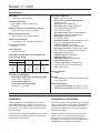
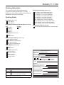
Specifications
Body Sizes
1 and 2-inch / DN 25 and 50
End Connection Style
NPT, ASME CL150 RF, CL300 RF, or
CL600 RF
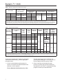
Maximum Inlet Pressure and Pressure Drops(1)
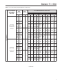
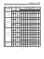
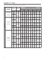
Up to 1500 psig / 103 bar, See Table 1
Maximum Outlet Pressure(1)
Up to 500 psig / 34.5 bar, See Table 2
Outlet Pressure Ranges
3 to 500 psig / 0.21 to 34.5 bar, See Table 2
Pressure Registration
Internal
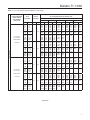
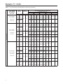
Flow Capacities
See Tables 3 and 4
Orifice Sizes and Wide-Open Flow Coefficients
for Relief Valve Sizing
ORIFICE SIZE
Inch
mm
1/8
3/16
1/4
3/8
1/2
3.2
4.8
6.4
9.5
13
Cg
CV
C1
13.9
31.3
55.1
122.5
216.0
0.49
1.11
2.03
4.61
8.18
28.4
28.2
27.2
26.6
26.4
Temperature Capabilities(1)
Nitrile (NBR), Nylon (PA), and Neoprene (CR):
-20 to 180°F / -29 to 82°C
Fluorocarbon (FKM) and
Polytetrafluoroethylene (PTFE):
0 to 300°F / -18 to 149°C
Construction Materials
Body: Cast iron, or steel
Spring Case and Diaphragm Adaptor:
Cast iron or steel
Orifice: Brass or stainless steel
Valve Disk: Nitrile (NBR), Nylon (PA),
Polytetrafluoroethylene (PTFE),
or Fluorocarbon (FKM)
Valve Disk Holder: Brass or stainless steel
Valve Carrier: Brass or stainless steel
Diaphragm: Neoprene (CR) or
Fluorocarbon (FKM)
Inlet Body Gaskets: Copper with brass trim or
stainless steel with stainless steel trim
All Other Gaskets: Composition
Lever: Zinc-plated steel or Stainless steel
Diaphragm Connector: Aluminum with brass
trim or stainless steel with stainless steel trim
Pitot Tube: Stainless steel
Regulator Spring: Plated steel
Adjusting Screw: Steel
Diaphragm Plate: Zinc-plated steel
Upper Spring Seat: Zinc
Lower Spring Seat: Zinc-plated steel
(low pressure) or Zinc (high pressure)
Vent: Type Y602-9
Spring Case Vent
1/4 NPT
Options
PTFE diaphragm protector, wire-seal adjusting
screw, and NACE
Approximate Weight
1-inch End Connection: 25 pounds / 11.3 kg
2-inch End Connection: 30 pounds / 13.6 kg
1. The pressure/temperature limits in this Bulletin and any applicable standard or code limitation should not be exceeded.
Installation
Overpressure Protection
These regulators may be installed in any position.
Some installations may require a remote vent line.
Protect all vent openings against the entrance of rain,
snow, debris, or any other foreign material that may
plug the opening.
As is the case with most regulators, these regulators
have an outlet pressure rating that is lower than the
inlet pressure rating. Overpressure protection is
needed if the actual inlet pressure can exceed the
outlet pressure rating.
Direction of flow through the regulator body must be
in the direction indicated by the flow direction arrow
found on the regulator body.
Regulator operation below the limits specified in
Tables 1 and 2 do not preclude the possibility of
damage from external sources or from debris in
the pipeline. The regulator should be inspected for
damage after any overpressure condition.
2