1
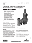
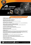
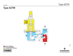
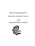
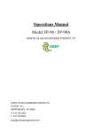
Installation Guide
English – May 2002
Types 627W and 627WH
Proof Test Pressure
This installation guide provides instructions for installation,
startup, and adjustment. To receive a copy of the instruction
manual,
contact
your
local
Fisher
Sales
Office or Sales Representative or view a copy at
www.FISHERregulators.com. For further information refer to:
Types 672W and 627WH Instruction Manual (form 5447,
D102504X012).
P.E.D. Category
This product may be used as a safety accessory with
pressure equipment in the following Pressure Equipment
Directive 97/23/EC categories. It may also be used outside
of the Pressure Equipment Directive using sound
engineering practice (SEP) per table below.
PRODUCT SIZE
CATEGORIES
DN 20-25 (3/4-1-inch) sizes only
SEP
DN 50 (2-inch)
I, II
Specifications
Available Constructions
Type 627W: Direct operated pressure reducing liquid
regulator.
Type 627WH: Type 627W with a diaphragm limiter to
deliver a higher outlet pressure.
Control Line Option: Type 627W or Type 627WH with
a stem seal between the body outlet pressure and
diaphragm case. Pressure is measured under the
diaphragm through the 6,4 mm (1/4-inch) NPT
screwed downstream control line connection.
Body Sizes
DN 20, 25, or 50 (3/4, 1, or 2-inch)
End Connection Styles
NPT Screwed; ANSI Class 150, 300, and 600 RF
flanged [DN 25 or 50 (1 and 2-inch sizes) only];
or PN 16/25/40 [DN 25 or 50 (1 and 2-inch sizes) only]
Maximum Inlet Pressures(1) (body rating)
140 bar (2000 psig) for screwed steel 70 bar (1000
psig) for ductile or body rating, whichever is lower
Maximum Operating Inlet and Differential
Pressures(1)
See table 1
Maximum Operating Outlet Pressures(1)
See table 1
Outlet Pressure Ranges(1)
See table 2
Orifice Diameters
Standard: 6,4 or 12,7 mm (1/4 or 1/2-inch)
Optional: 2,4; 3,2; 4,8; or 9,5 mm (3/32, 1/8, 3/16, or
3/8-inch)
All Pressure Retaining Components have been
proof tested per Directive 97/23/EC - Annex 1,
Section 7.4
Temperature Capabilities(1)
Nitrile (NBR): -40 to 82°C (-40 to 180°F)
Fluoroelastomer (FKM): -18 to 149°C (0 to 300°F)
Ethylenepropylene (EPDM): -40 to 149°C (-40 to
300°F)
Perfluoroelastomer (FFKM): -18 to 149°C (0 to 300°F)
Nylon (PA): -40 to 93°C (-40 to 200°F)
Teflon (PTFE): -40 to 149°C (-40 to 300°F)
Installation
Only qualified personnel should install or service
a regulator. Regulators should be installed,
operated, and maintained in accordance with
international and applicable codes and
regulations, and Fisher instructions.
If the regulator vents fluid or a leak develops in
the system, it indicates that service is required.
Failure to take the regulator out of service
immediately may create a hazardous condition.
Personal injury, equipment damage, or leakage
due to escaping fluid or bursting of pressurecontaining parts may result if this regulator is
overpressured or is installed where service
conditions could exceed the limits given in the
Specifications section, or where conditions
exceed any ratings of the adjacent piping or piping
connections.
To avoid such injury or damage, provide pressurerelieving or pressure-limiting devices (as required
by the appropriate code, regulation, or standard)
to prevent service conditions from exceeding
limits.
Additionally, physical damage to the regulator
could result in personal injury and property
damage due to escaping fluid. To avoid such injury
and damage, install the regulator in a safe
location.
Clean out all pipelines before installation of the regulator
and check to be sure the regulator has not been damaged
or has collected foreign material during shipping. For NPT
bodies, apply pipe compound to the male pipe threads. For
flanged bodies, use suitable line gaskets and approved
piping and bolting practices. Install the regulator in any
position desired, unless otherwise specified, but be sure
flow through the body is in the direction indicated by the
arrow on the body.
1. The pressure/temperature limits in this installation guide and any applicable
standard or code limitation should not be exceeded.
www.FISHERregulators.com
D102504XENG
Introduction
Types 627W and 627WH
Note
Startup
It is important that the regulator be installed so that
the vent hole in the spring case is unobstructed at all
times. For outdoor installations, the regulator should
be located away from vehicular traffic and positioned
so that water, ice, and other foreign materials cannot
enter the spring case through the vent. Avoid placing
the regulator beneath eaves or downspouts, and be
sure it is above the probable snow level.
Overpressure Protection
The recommended pressure limitations are stamped on the
regulator nameplate. Some type of overpressure protection
is needed if the actual inlet pressure exceeds the maximum
operating outlet pressure rating. Overpressure protection
should also be provided if the regulator inlet pressure is
greater than the safe working pressure of the downstream
equipment.
Regulator operation below the maximum pressure limitations
does not preclude the possibility of damage from external
sources or debris in the line. The regulator should be inspected
for damage after any overpressure condition.
The regulator is factory set at approximately the midpoint of
the spring range or the pressure requested, so an initial
adjustment may be required to give the desired results. With
proper installation completed and relief valves properly
adjusted, slowly open the upstream and downstream shutoff
valves.
Adjustment
To change the outlet pressure, remove the closing cap or
loosen the locknut and turn the adjusting screw clockwise
to increase outlet pressure or counterclockwise to decrease
pressure. Monitor the outlet pressure with a test gauge
during the adjustment. Replace the closing cap or tighten
the locknut to maintain the desired setting.
Taking Out of Service (Shutdown)
To avoid personal injury resulting from sudden
release of pressure, isolate the regulator from all
pressure before attempting disassembly.
Table 1. Maximum Spring and Diaphragm Casing Pressure(1)
SPRING AND
DIAPHRAGM CASING
STYLE
TYPE 627W
bar (psig)
TYPE
627WH
psig (bar)
Maximum pressure to spring and diaphragm casings to prevent leak to atmosphere (internal parts
damage may occur)
Ductile Iron
17,2 (250)
--- ---
Steel or Stainless Steel
17,2 (250)
55,2 (800)
Maximum pressure to spring and diaphragm casings to prevent burst of casings during abnormal
operation (leak to atmosphere and internal parts damage may occur)
Ductile Iron
32,1 (465)
--- ---
Steel or Stainless Steel
103 (1500)
103 (1500)
Maximum diaphragm casing overpressure (above setpoint) to prevent damage to internal parts.
All Styles
4,1 (60)
8,3 (120)
1. If the spring case is pressurized, a metal adjusting screw cap is required.
Table 2. Maximum Inlet Pressure, Differential Pressure, and Outlet Pressure Ranges
TYPE
OUTLET PRESSURE
RANGE, SPRING PART NO.,
AND COLOR, BAR (psig)
0,69 to 1,4 (10 to 20)
10B 3076X 012
yellow
1,0 to 2,8 (15 to 40)
10B 3077X 012
green
ORIFICE
DIAMETER
MAXIMUM INLET PRESSURE
BAR (psig)
MAXIMUM DIFFERENTIAL PRESSURE
BAR (psig)
elastomer disk
nylon disk
elastomer disk
nylon disk
6,4 (1/4)
15,2 (220)
29,0 (420)
13,8 (200)
27,6 (400)
12,7 (1/2)
15,2 (220)
17,2 (250)
13,8 (200)
17,2 (250)
6,4 (1/4)
16,6 (240)
30,3 (440)
13,8 (200)
27,6 (400)
12,7 (1/2)
16,6 (240)
20,7 (300)
13,8 (200)
20,7 (300)
6,4 (1/4)
19,3 (280)
33,1 (480)
13,8 (200)
27,6 (400)
12,7 (1/2)
19,3 (280)
33,1 (480)
13,8 (200)
27,6 (400)
627W
2,4 to 5,5 (35 to 80)
10B 3079X 012
blue
4,8 to 10,3 (70 to 150)
10B 3078X 012
red
6,4 (1/4)
24,1 (350)
37,9 (550)
13,8 (200)
27,6 (400)
12,7 (1/2)
24,1 (350)
37,9 (550)
13,8 (200)
27,6 (400)
9,7 to 17,2 (140 to 250)
10B 3078X 012
blue
6,4 (1/4)
31,0 (450)
44,8 (650)
13,8 (200)
27,6 (400)
12,7 (1/2)
31,0 (450)
34,5 (500)
13,8 (200)
17,2 (250)
6,4 (1/4)
48,3 (700)
62,1 (900)
13,8 (200)
27,6 (400)
12,7 (1/2)
48,3 (700)
51,7 (750)
13,8 (200)
17,2 (250)
627WH
16,6 to 34,5 (240 to 500)
10B 3079X 012
red
2
Types 627W and 627WH
Parts List
Key Description
Key Description
1
2
3
8
9
10
11
12
13
14
15
16
17
18
19
23
24
29 Spring Case
30 Vent
31 Lower Spring Seat
(627W only)
32 Spring
33 Upper Spring Seat
34 Locknut
35 Adjusting Screw
36 Adjusting Screw Cap
37 Cap Screw
44 O-Ring
45 Backup Ring
46 Cap Screw
50 Diaphragm Limiter
(627WH only)
51 O-Ring
52 O-Ring
Body
Orifice
Diaphragm Casing
Stem Guide
Valve Plug Assembly
Stem
Stem O-Ring
Stem Backup Ring
Hair Pin Clip
Drive Pin
Lever
Lever Retainer
Lever Pin
Cap Screw
Pusher Post Assembly
Diaphragm
Diaphragm Head
34B7395
37B9752
Figure 1. Type 627W Regulator Components
Figure 2. Type 627WH Regulator Components
3
Types 627W and 627WH
©Fisher Controls International, Inc., 2002; All Rights Reserved
Fisher and Fisher Regulators are marks owned by Fisher Controls International, Inc. The Emerson logo is a trade mark and service mark of Emerson Electric Co.
All other marks are the property of their respective owners.
The contents of this publication are presented for informational purposes only, and while every effort has been made to ensure their accuracy, they are not to be construed as warranties or guarantees, express
or implied, regarding the products or services described herein or their use or applicability. We reserve the right to modify or improve the designs or specifications of such products at any time without notice.
For information, contact Fisher Controls, International:
Within USA (800) 588-5853 – Outside USA (972) 542-0132
France – (33) 23-733-4700
Singapore – (65) 770-8320
Mexico – (52) 57-28-0888
Printed in U.S.A.
www.FISHERregulators.com