1
4801_QIG_RevHA.fm Page 1 Tuesday, February 26, 2008 12:17 PM
Quick Installation Guide
00825-0100-4801, Rev HA
February 2008
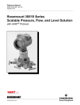
Rosemount 3051S
Rosemount 3051S Series Pressure
Transmitter with HART® Protocol
Rosemount 3051SF Series Flowmeter
Transmitter with HART® Protocol
Start
Step 1: Mount the Transmitter
Step 2: Consider Housing Rotation
Step 3: Set Switches and Jumpers
Step 4: Connect Wiring and Power Up
Step 5: Verify Configuration
Step 6: Trim the Transmitter
Safety Instrumented Systems
Product Certifications
End
© 2008 Rosemount Inc. All rights reserved. All marks property of owner. Rosemount and the
Rosemount logotype are registered trademarks of Rosemount Inc.
HART®
¢00825-0100-4801J¤
www.rosemount.com
4801_QIG_RevHA.fm Page 2 Tuesday, February 26, 2008 12:17 PM
Quick Installation Guide
Rosemount 3051S
Rosemount Inc.
8200 Market Boulevard
Chanhassen, MN USA 55317
T (US) (800) 999-9307
T (Intnl) (952) 906-8888
F (952) 949-7001
00825-0100-4801, Rev HA
February 2008
Emerson Process Management
GmbH & Co. OHG
Argelsrieder Feld 3
82234 Wessling
Germany
T 49 (8153) 9390, F49 (8153) 939172
Emerson Process Management
Asia Pacific Private Limited
Beijing Rosemount Far East Instrument
Co., Limited
1 Pandan Crescent
Singapore 128461
T (65) 6777 8211
F (65) 6777 0947/65 6777 0743
No. 6 North Street, Hepingli, Dong Cheng District
Beijing 100013, China
T (86) (10) 6428 2233
F (86) (10) 6422 8586
IMPORTANT NOTICE
This installation guide provides basic guidelines for Rosemount 3051S
transmitters (reference manual document number 00809-0100-4801). It
also provides the basic electronics guidelines for the 3051SFA
(reference manual document number 00809-0100-4809), 3051SFC
(reference manual document number 00809-0100-4810), and 3051SFP
(reference manual document number 00809-0100-4686). It does not
provide instructions for diagnostics, maintenance, service, or
troubleshooting. This document is also available electronically on
www.rosemount.com.
2
4801_QIG_RevHA.fm Page 3 Tuesday, February 26, 2008 12:17 PM
Quick Installation Guide
00825-0100-4801, Rev HA
February 2008
Rosemount 3051S
WARNING
Explosions could result in death or serious injury:
Installation of this transmitter in an explosive environment must be in
accordance with the appropriate local, national, and international
standards, codes, and practices. Please review the approvals section of
the 3051S reference manual for any restrictions associated with a safe
installation.
• Before connecting a HART communicator in an explosive
atmosphere, ensure the instruments in the loop are installed in
accordance with intrinsically safe or non-incendive field wiring
practices.
• In an Explosion-Proof/Flame-Proof installation, do not remove the
transmitter covers when power is applied to the unit.
Process leaks may cause harm or result in death.
• Install and tighten process connectors before applying pressure.
Electrical shock can result in death or serious injury.
• Avoid contact with the leads and terminals. High voltage that may be
present on leads can cause electrical shock.
3
4801_QIG_RevHA.fm Page 4 Tuesday, February 26, 2008 12:17 PM
Quick Installation Guide
Rosemount 3051S
00825-0100-4801, Rev HA
February 2008
STEP 1: MOUNT THE TRANSMITTER
Liquid Flow Applications
1. Place taps to the side of the line.
2. Mount beside or below the taps.
3. Mount the transmitter so that the
drain/vent valves are oriented
upward.
Gas Flow Applications
1. Place taps in the top or side of
the line.
2. Mount beside or above the taps.
Steam Flow Applications
1. Place taps to the side of the line.
2. Mount beside or below the taps.
3. Fill impulse lines with water.
4
4801_QIG_RevHA.fm Page 5 Tuesday, February 26, 2008 12:17 PM
Quick Installation Guide
00825-0100-4801, Rev HA
February 2008
Rosemount 3051S
STEP 1 CONTINUED...
Panel Mount
Coplanar™ Flange
Pipe Mount
Traditional Flange
In-line
PlantWeb™
Housings
Junction Box
Remote Mount Display
5
4801_QIG_RevHA.fm Page 6 Tuesday, February 26, 2008 12:17 PM
Quick Installation Guide
00825-0100-4801, Rev HA
February 2008
Rosemount 3051S
STEP 2: CONSIDER HOUSING ROTATION
To improve field access to wiring or to
better view the optional LCD display:
1. Loosen the housing rotation set
screw.
2. First rotate the housing clockwise
to the desired location. If the
desired location cannot be
achieved due to thread limit,
rotate the housing counter
clockwise to the desired location
(up to 360° from thread limit).
3. Retighten the housing rotation set
screw.
Figure 1. Transmitter Housing
Set Screw
PlantWeb
Junction Box
Housing Rotation Set
Screw (3/32-inch)
STEP 3: SET SWITCHES AND JUMPERS
If alarm and security adjustment option is not installed, the transmitter
will operate normally with the default alarm condition alarm high and
the security off.
Figure 2. Transmitter Switch and Jumper Configuration
PlantWeb
Meter/
Adjustment
Module
Security
Junction Box
Alarm
Slide the security and alarm
switches into the preferred position
by using a small screwdriver.
(A LCD display or an adjustment
module must be in place to activate
the switches.)
6
Security
Alarm
Pull the jumpers out and rotate 90°
into desired position to set the security
and alarm.
4801_QIG_RevHA.fm Page 7 Tuesday, February 26, 2008 12:17 PM
Quick Installation Guide
00825-0100-4801, Rev HA
February 2008
Rosemount 3051S
STEP 4: CONNECT WIRING AND POWER UP
Use the following steps to wire the transmitter:
1. Remove the housing cover labeled “Field Terminals.”
2. Connect the positive lead to the “+” terminal, and the negative lead
to the “–” terminal.
NOTE
Do not connect the power across the test terminals. Power could
damage the test diode in the test connection. Twisted pairs yield best
results. For single compartment housing (Junction Box housing),
shielded signal wiring should be used in high EMI/RFI environments.
Use 24 AWG to 14 AWG wire and do not exceed 5,000 feet
(1500 meters).
3. Plug and seal the unused conduit connection.
4. If applicable, install wiring with a drip loop. Arrange the drip loop
so the bottom is lower than the conduit connections and the
transmitter housing.
5. Replace the housing cover.
The figures below show the wiring connections necessary to power a
3051S and enable communications with a hand-held HART
communicator.
Figure 3. Transmitter Wiring
PlantWeb Housing Wiring
Junction Box Housing Wiring
RL ≥ 250 Ω
RL ≥ 250 Ω
Power
Supply
NOTE
Installation of the transient protection terminal block does not
provide transient protection unless the 3051S case is properly
grounded.
Power
Supply
7
4801_QIG_RevHA.fm Page 8 Tuesday, February 26, 2008 12:17 PM
Quick Installation Guide
Rosemount 3051S
00825-0100-4801, Rev HA
February 2008
STEP 4 CONTINUED...
Remote Display Wiring and Power Up
The Remote Mount Display and Interface system consists of a local
transmitter and a remote mount LCD display assembly. The local
3051S transmitter assembly includes a Junction Box housing with a
three position terminal block integrally mounted to a SuperModule.
The remote mount LCD display assembly consists of a dual
compartment PlantWeb housing with a seven position terminal block.
See Figure 4 on page 9 for complete wiring instructions. The following
is a list of necessary information specific to the Remote Mount Display
system:
• Each terminal block is unique for the remote display system.
• A 316 SST housing adapter is permanently secured to the remote
mount LCD display PlantWeb housing providing an external
ground and a means for field mounting with the provided mounting
bracket.
• A cable is required for wiring between the transmitter and remote
mount LCD display. The cable length is limited to 100 ft.
• 50 ft. (option M8) or 100 ft. (option M9) cable is provided for wiring
between the transmitter and remote mount LCD display. Option
M7 does not include cable; see recommended specifications
below:
Cable type: Recommend Belden 3084A DeviceNet cable or Belden
123084A Armored DeviceNet cable. Other comparable cable may be
used as long as it has independent dual twisted shielded pair wires
with an outer shield. The Power wires must be 22 AWG minimum and
the CAN communication wires must be 24 AWG minimum.
Cable length: Up to 100 feet depending upon cable capacitance.
Cable capacitance: The capacitance from the CAN communications
line to the CAN return line as wired must be less than 5000 picofarads
total. This allows up to 50 picofarads per foot for a 100 foot cable.
8
4801_QIG_RevHA.fm Page 9 Tuesday, February 26, 2008 12:17 PM
Quick Installation Guide
00825-0100-4801, Rev HA
February 2008
Rosemount 3051S
STEP 4 CONTINUED...
Intrinsic Safety Consideration: The transmitter assembly with
remote display has been approved with Belden 3084A DeviceNet
cable. Alternate cable may be used as long as the transmitter with
remote display and cable is configured according to the installation
control drawing or certificate. Refer to appropriate approval certificate
or control drawing in Appendix B of the 3051S reference manual for
remote cable IS requirements.
IMPORTANT
Do not apply power to the remote communications terminal. Follow
wiring instructions carefully to prevent damage to system components.
Figure 4. Remote Mount Display wiring diagram
Junction Box Housing
Remote Mount Display
(white) 24 AWG
(blue) 24 AWG
(black) 22 AWG
(red) 22 AWG
4-20 mA
9
4801_QIG_RevHA.fm Page 10 Tuesday, February 26, 2008 12:17 PM
Quick Installation Guide
Rosemount 3051S
00825-0100-4801, Rev HA
February 2008
STEP 4 CONTINUED...
NOTE
Wire colors provided on page 9 are per Belden 3084A DeviceNet
cable. Wire color may vary depending on cable selected.
Belden 3084A DeviceNet cable includes a ground shield. This shield
must be connected to earth ground at either the SuperModule or the
Remote Display, but not both.
Quick Connect Wiring
As standard, the 3051S Quick Connect arrives properly assembled to
the SuperModule and is ready for installation. Cordsets and Field
Wireable Connectors (in shaded area) are sold separately.
Figure 5. Rosemount 3051S Quick Connect Exploded View
Straight Field
Wireable
Connector(1)(3)
Quick Connect
Housing
Right Angle Field Wireable
Connector(2)(3)
Cordset(4)
Coupling Nut
Quick Connect Coupling Nut
(1) Order part number
03151-9063-0001.
(2) Order part number
03151-9063-0002.
(3) Field wiring supplied by customer.
(4) Supplied by cordset vendor.
IMPORTANT
If Quick Connect is ordered as a 300S spare housing or is removed
from the SuperModule, follow the instructions below for proper
assembly prior to field wiring.
1. Place the Quick Connect onto the SuperModule. To ensure proper
pin alignment, remove coupling nut prior to installing quick connect
onto SuperModule.
10
4801_QIG_RevHA.fm Page 11 Tuesday, February 26, 2008 12:17 PM
Quick Installation Guide
00825-0100-4801, Rev HA
February 2008
Rosemount 3051S
STEP 4 CONTINUED...
2. Place coupling nut over quick connect and wrench tighten to a
maximum of 300 in-lb. (34 N-m).
3. Tighten the set screw using a 3/32-in hex wrench.
4. Install Cordset/ Field Wireable Connectors onto the Quick Connect.
Do not over tighten.
Figure 6. Quick Connect Housing Pin-Out
For other wiring
details, refer to pin-out
drawing and the
cordset
manufacturer’s
installation
instructions.
“+”
“–”
No Connection
Ground
Conduit Electrical Connector Wiring (Option GE or GM)
For 3051S transmitters with conduit electrical connectors GE or GM,
refer to the cordset manufacturer’s installation instructions for wiring
details. For FM Intrinsically Safe, non-incendive or FM FISCO
Intrinsically Safe hazardous locations, install in accordance with
Rosemount drawing 03151-1009 to maintain outdoor rating (NEMA 4X
and IP66.) See Appendix B of the 3051S reference manual.
11
4801_QIG_RevHA.fm Page 12 Tuesday, February 26, 2008 12:17 PM
Quick Installation Guide
00825-0100-4801, Rev HA
February 2008
Rosemount 3051S
STEP 4 CONTINUED...
Power Supply
The dc power supply should provide power with less than two percent
ripple. The total resistance load is the sum of the resistance of the
signal leads and the load resistance of the controller, indicator, and
related pieces. Note that the resistance of intrinsic safety barriers, if
used, must be included.
Figure 7. Load Limitation
Standard Transmitter
HART Diagnostics Transmitter
(option code DA1)
Maximum Loop Resistance =
43.5 * (Power Supply Voltage – 10.5)
Maximum Loop Resistance =
43.5 * (Power Supply Voltage – 12.0)
1322
Load (Ohms)
Load (Ohms)
1387
1000
500
Operating
Region
1000
500
Operating
Region
0
0
10.5
20
12.0
30
Voltage (V dc)
42.4
20
The HART communicator requires a minimum loop
resistance of 250Ω for communication.
12
30
Voltage (V dc)
42.4
4801_QIG_RevHA.fm Page 13 Tuesday, February 26, 2008 12:17 PM
Quick Installation Guide
00825-0100-4801, Rev HA
February 2008
Rosemount 3051S
STEP 5: VERIFY CONFIGURATION
Use any HART-compliant master to communicate with and verify
configuration of the 3051S. For the HART Diagnostics transmitter
(option code DA1), DD revision 3051S HDT Dev. 1 Rev. 1 is required.
A check (⻫) indicates the basic configuration parameters. At a
minimum, these parameters should be verified as part of the
configuration and startup procedure.
Table 1. HART Fast Key Sequence
Function
Fast Key Sequence
Alarm Level Configuration
1, 4, 2, 7, 7
Alarm and Saturation Levels
1, 4, 2, 7
Analog Output Alarm Direction
1, 4, 2, 7, 6
Analog Output Trim
1, 2, 3, 2
Burst Mode On/Off
1, 4, 3, 3, 3
Burst Options
1, 4, 3, 3, 4
⻫ Damping
1, 3, 6
Date
1, 3, 4, 1
Descriptor
1, 3, 4, 2
Digital To Analog Trim (4-20 mA
1, 2, 3, 2, 1
Output)
Field Device Information
1, 4, 4, 1
LCD Display Configuration
1, 3, 7
Loop Test
1, 2, 2
Lower Sensor Trim
1, 2, 3, 3, 2
Message
1, 3, 4, 3
Number of Requested Preambles
1, 4, 3, 3, 2
Pressure Alert Configuration
1, 4, 3, 5, 3
Poll Address
1, 4, 3, 3, 1
Poll a Multidropped Transmitter
Left Arrow, 3, 1, 1
Remapping
1, 4, 3, 6
Rerange- Keypad Input
1, 2, 3, 1, 1
Continued on Next Page
13
4801_QIG_RevHA.fm Page 14 Tuesday, February 26, 2008 12:17 PM
Quick Installation Guide
Rosemount 3051S
00825-0100-4801, Rev HA
February 2008
STEP 5 CONTINUED...
Function
Saturation Level Configuration
Scaled D/A Trim (4–20 mA Output)
Scaled Variable Configuration
Self Test (Transmitter)
Sensor Information
Sensor Temperature
Sensor Trim
Sensor Trim Points
Status
⻫ Tag
Temperature Alert Configuration
⻫ Transfer Function
(Setting Output Type)
Transmitter Security (Write Protect)
⻫ Units (Process Variable)
Upper Sensor Trim
Zero Trim
14
Fast Key Sequence
1, 4, 2, 7, 8
1, 2, 3, 2, 2
1, 4, 3, 4, 7
1, 2, 1, 1
1, 4, 4, 2
1, 1, 4
1, 2, 3, 3
1, 2, 3, 3, 5
1, 2, 1, 2
1, 3, 1
1, 4, 3, 5, 4
1, 3, 5
1, 3, 4, 5
1, 3, 2
1, 2, 3, 3, 3
1, 2, 3, 3, 1
4801_QIG_RevHA.fm Page 15 Tuesday, February 26, 2008 12:17 PM
Quick Installation Guide
00825-0100-4801, Rev HA
February 2008
Rosemount 3051S
STEP 6: TRIM THE TRANSMITTER
Transmitters are shipped fully calibrated per request or by the factory
default of full scale (lower range value = zero, upper range value =
upper range limit).
Zero Trim
A zero trim is a single-point adjustment used for compensating
mounting position and line pressure effects. When performing a zero
trim, ensure that the equalizing valve is open and all wet legs are filled
to the correct level.
If zero offset is less than 3% of true zero, follow the “Using the HART
Communicator” instructions below to perform a zero trim. If zero offset
is greater than 3% of true zero, follow the “Using the Transmitter Zero
Adjustment Button” instructions below to rerange. If hardware
adjustments are not available, see the 3051S Reference Manual
(document number 00809-0100-4801) to perform a rerange using the
HART Communicator.
Using the HART Communicator
HART Fast Keys
1, 2, 3, 3, 1
Steps
1. Equalize or vent the transmitter and connect HART
communicator.
2. At the menu, input the HART Fast Key sequence.
3. Follow the commands to perform a zero trim.
15
4801_QIG_RevHA.fm Page 16 Tuesday, February 26, 2008 12:17 PM
Quick Installation Guide
Rosemount 3051S
00825-0100-4801, Rev HA
February 2008
Using the Transmitter Zero Adjustment Button
Push and hold the zero adjustment button for at least two seconds but
no longer than ten seconds.
Figure 8. Transmitter Adjustment Buttons
PlantWeb
Zero
16
Span
Junction Box
Zero
Span
4801_QIG_RevHA.fm Page 17 Tuesday, February 26, 2008 12:17 PM
Quick Installation Guide
00825-0100-4801, Rev HA
February 2008
Rosemount 3051S
SAFETY INSTRUMENTED SYSTEMS
Additional Safety Instrumented Systems information is available in the
Rosemount 3051S reference manual (document number
00809-0100-4801). The manual is available electronically on
www.rosemount.com or by contacting an Emerson Process
Management representative.
3051S Safety-Certified Identification
All 3051S transmitters must be identified as safety-certified before
installing into SIS systems.
NOTE
There are two versions of safety-certified 3051S pressure transmitters.
For transmitters with a yellow SIS circuit board installed and output
code B in the model number, please refer to Manual Supplement
00809-0700-4801.
To identify a safety-certified 3051S:
1. Connect a HART host to the transmitter.
2. Check the software to verify that the software revision is 7 or
higher.
Fast Key Sequence - 1, 5
Revision #’s
Fld Dev Rev
7
Software Rev
7
Hardware Rev
16
3. Verify that option code QT is included in the transmitter model
code.
17
4801_QIG_RevHA.fm Page 18 Tuesday, February 26, 2008 12:17 PM
Quick Installation Guide
Rosemount 3051S
00825-0100-4801, Rev HA
February 2008
Installation
No special installation is required in addition to the standard
installation practices outlined in this document. Always ensure a
proper seal by installing the electronics housing covers so that metal
contacts metal.
The loop should be designed so the terminal voltage does not drop
below 10.5 Vdc when the transmitter output is 23.0 mA.
If hardware security switches are installed, the security switch should
be in the “ON” position during normal operation. See Figure 2 on
page 6. If hardware security switches are not installed, security should
be “ON” in the software to prevent accidental or deliberate change of
configuration data during normal operation.
Configuration
Use any HART-compliant master to communicate with and verify
configuration of the 3051S Safety-Certified Pressure Transmitter (see
Table 1 on page 13 and 14 to verify configuration).
User-selected damping will affect the transmitters ability to respond to
changes in the applied process. The damping value + response time
should not exceed the loop requirements.
18
4801_QIG_RevHA.fm Page 19 Tuesday, February 26, 2008 12:17 PM
Quick Installation Guide
00825-0100-4801, Rev HA
February 2008
Rosemount 3051S
NOTES
1. Transmitter output is not safety-rated during the following:
configuration changes, multidrop, loop test. Alternative means should
be used to ensure process safety during transmitter configuration and
maintenance activities.
2. DCS or safety logic solver should be configured to match transmitter
configuration. Figure 9 identifies the three alarm levels available and
their operation values.
Figure 9. Alarm Levels
Rosemount Alarm Level
Normal Operation
3.75 mA(1)
3.9 mA
low saturation
20 mA
4 mA
20.8 mA
high saturation
21.75(2)
Namur Alarm Level
Normal Operation
3.6 mA(1)
3.8 mA
low saturation
4 mA
20 mA
20.5 mA
high saturation
22.5(2)
Custom Alarm Level(3)(4)
Normal Operation
3.6 - 3.8 mA(1)
4 mA
3.7 - 3.9 mA
low saturation
20 mA
20.2 - 23.0(2)
20.1 - 20.5 mA
high saturation
(1) Transmitter Failure, hardware or software alarm in LO position.
(2) Transmitter Failure, hardware or software alarm in HI position.
(3) High alarm must be at least 0.1 mA higher than the high saturation value.
(4) Low alarm must be at least 0.1 mA lower than the low saturation value.
19
4801_QIG_RevHA.fm Page 20 Tuesday, February 26, 2008 12:17 PM
Quick Installation Guide
Rosemount 3051S
00825-0100-4801, Rev HA
February 2008
Setting the alarm values and direction is dependent on whether or not
the hardware switch option is installed. You can use a HART master or
communicator to set the Alarm and Saturation values.
Switches installed
1. If using a communicator, use the following fast key sequence to set
the Alarm and Saturation values.
Alarm Levels - Fast Key; 1, 4, 2, 7, 7
Saturation Levels - Fast Key; 1, 4, 2, 7, 8
2. Manually set the direction for the Alarm to HI or LO using the
ALARM switch as shown in Figure 2 on page 6.
Switches not installed
If using a communicator, use the following fast key sequence to set the
Alarm and Saturation values and the Alarm Direction:
Alarm Levels - Fast Key; 1, 4, 2, 7, 7
Saturation Levels - Fast Key; 1, 4, 2, 7, 8
Alarm Direction Fast Key; 1, 4, 2, 7, 6
20
4801_QIG_RevHA.fm Page 21 Tuesday, February 26, 2008 12:17 PM
Quick Installation Guide
00825-0100-4801, Rev HA
February 2008
Rosemount 3051S
Operation and Maintenance
Proof Test and Inspection
The following proof tests are recommended. Proof test results
and corrective actions taken must be documented at
www.emersonprocess.com/rosemount/safety/certtechdocumentation.
htm in the event that an error is found in the safety functionality.
Use "Table 1: HART Fast Key Sequence" to perform a Loop Test,
Analog Output Trim, or Sensor Trim. See the 3051S reference manual
for additional information.
Proof Test 1
Conducting an analog output Loop Test satisfies the proof test
requirements and will detect more than 52% of DU failures not
detected by the 3051S_C or 3051S_L automatic diagnostics, and
more than 62% of DU failures not detected by the 3051S_T automatic
diagnostics.
Required tools: HART host/communicator and mA meter.
1.
2.
3.
4.
On HART host/communicator enter the Fast Key Sequence 1, 2, 2.
Select “4 Other.”
Enter the milliampere value representing a high alarm state.
Check the reference meter to verify the mA output corresponds to
the entered value.
5. Enter the milliampere value representing a low alarm state.
6. Check the reference meter to verify the mA output corresponds to
the entered value.
7. Document the test results per your requirements.
21
4801_QIG_RevHA.fm Page 22 Tuesday, February 26, 2008 12:17 PM
Quick Installation Guide
Rosemount 3051S
00825-0100-4801, Rev HA
February 2008
Proof Test 2
This proof test, when combined with the Proof Test 1, will detect over
92% of DU failures not detected by the 3051S_C or 3051S_L
automatic diagnostics, and over 95% of DU failures not detected by
the 3051S_T automatic diagnostics.
Required tools: HART host/communicator and pressure calibration
equipment.
1. Perform a minimum two point sensor calibration check using the
4-20mA range points as the calibration points.
2. Check the reference mA meter to verify the mA output corresponds
to the pressure input value.
3. If necessary, use one of the “Trim” procedures available in the
3051S reference manual to calibrate.
4. Document the test results per your requirements.
NOTE
The user determines the proof-test requirements for impulse piping.
Visual Inspection
Not required.
Special Tools
Not required.
Product Repair
All failures detected by the transmitter diagnostics or by the proof-test
must be reported. Feedback can be submitted electronically at
www.emersonprocess.com/rosemount/safety/certtechdocumentation.
htm.
The 3051S is repairable by major component replacement. Follow the
instructions in the 3051S reference manual (document number
00809-0100-4801) for additional information.
22
4801_QIG_RevHA.fm Page 23 Tuesday, February 26, 2008 12:17 PM
Quick Installation Guide
00825-0100-4801, Rev HA
February 2008
Rosemount 3051S
Reference
Certification
The 3051S Safety-Certified Pressure Transmitter was designed,
developed, and audited to be compliant to IEC 61508 safety-certified
SIL 2 Claim Limit.
Specifications
The 3051S Safety-Certified Pressure Transmitter must be operated in
accordance to the functional and performance specifications provided
in the 3051S reference manual.
Failure Rate Data
The FMEDA report includes failure rates and common cause Beta
factor estimates. This report is available at
www.emersonprocess.com/rosemount/safety/certtechdocumentation.
htm.
3051S Safety-Certified Pressure Transmitter Failure Values
Safety accuracy: 2.0%(1)
Safety response time: 1.5 seconds
Self-diagnostics Test Interval: At least once per hour
Product Life
50 years – based on worst case component wear-out mechanisms –
not based on wear-out process wetted materials.
(1) A 2% variation of the transmitter mA output is allowed before a safety trip. Trip
values in the DCS or safety logic solver should be derated by 2%.
23
4801_QIG_RevHA.fm Page 24 Tuesday, February 26, 2008 12:17 PM
Quick Installation Guide
Rosemount 3051S
00825-0100-4801, Rev HA
February 2008
PRODUCT CERTIFICATIONS
Approved Manufacturing Locations
Rosemount Inc. — Chanhassen, Minnesota USA
Fisher-Rosemount GmbH & Co. — Wessling, Germany
Emerson Process Management Asia Pacific Private Limited — Singapore
Beijing Rosemount Far East Instrument Co., LTD — Beijing, China
Emerson Process Management LTDA — Sorocaba, Brazil
Emerson Process Management (India) Pvt. Ltd. — Daman, India
European Directive Information
The EC declaration of conformity can be found on page 32. The most
recent revision can be found at www.rosemount.com.
Ordinary Location Certification for FM Approvals
As standard, the transmitter has been examined and tested to determine
that the design meets basic electrical, mechanical, and fire protection
requirements by FM Approvals, a nationally recognized testing laboratory
(NRTL) as accredited by the Federal Occupational Safety and Health
Administration (OSHA).
24
4801_QIG_RevHA.fm Page 25 Tuesday, February 26, 2008 12:17 PM
Quick Installation Guide
00825-0100-4801, Rev HA
February 2008
Rosemount 3051S
Hazardous Locations Certifications
North American Certifications
FM Approvals
E5 Explosion proof for Class I, Division 1, Groups B, C, and D;
dust-ignition proof for Class II and Class III, Division 1, Groups E,
F, and G; hazardous locations; enclosure Type 4X, conduit seal
not required when installed according to Rosemount drawing
03151-1003.
I5
Intrinsically Safe for use in Class I, Division 1, Groups A, B, C,
and D; Class II, Division 1, Groups E, F, and G; Class III, Division
1; Class I, Zone 0 AEx ia IIC when connected in accordance with
Rosemount drawing 03151-1006; Non-incendive for Class I,
Division 2, Groups A, B, C, and D, Enclosure Type 4X
For entity parameters see control drawing 03151-1006.
Canadian Standards Association (CSA)
E6 Explosion-Proof for Class I, Division 1, Groups B, C, and D;
Dust-Ignition-Proof for Class II and Class III, Division 1, Groups
E, F, and G; suitable for Class I, Division 2, Groups A, B, C, and
D, when installed per Rosemount drawing 03151-1013, CSA
Enclosure Type 4X; conduit seal not required.
I6
Intrinsically Safe for Class I, Division 1, Groups A, B, C, and D
when connected in accordance with Rosemount drawings
03151-1016;
For entity parameters see control drawing 03151-1016.
25
4801_QIG_RevHA.fm Page 26 Tuesday, February 26, 2008 12:17 PM
Quick Installation Guide
00825-0100-4801, Rev HA
February 2008
Rosemount 3051S
European Certifications
I1
ATEX Intrinsic Safety
Certificate No.: BAS01ATEX1303X
II 1 G
EEx ia IIC T4 (Ta = -60 °C to 70 °C)
-HART/Remote Display/Quick Connect/HART Diagnostics
1180
Table 2. Input Parameters
Loop / Power
Groups
Ui = 30V
Ii = 300 mA
Pi = 1.0W
Ci = 30nF
Ci = 11.4nF
Ci = 0
Li = 0
Li = 60 µH
All
All
All
SuperModule™/Quick Connect
With PlantWeb or Junction Box Housing
Remote Display
All Except Remote Display
Remote Display
Special Conditions for Safe Use (X)
1. The apparatus, excluding the Types 3051 S-T and 3051 S-C
(In-line and Coplanar SuperModule Platforms respectively), is
not capable of withstanding the 500V test as defined in Clause
6.4.12 of EN 50020. This must be considered during
installation.
2. The terminal pins of the Types 3051 S-T and 3051 S-C must
be protected to IP20 minimum.
N1 ATEX Type n
Certificate No.: BAS01ATEX3304X
II 3 G
EEx nL IIC T4 (Ta = -40 °C TO 70 °C)
Ui = 45 Vdc max
IP66
26
4801_QIG_RevHA.fm Page 27 Tuesday, February 26, 2008 12:17 PM
Quick Installation Guide
00825-0100-4801, Rev HA
February 2008
Rosemount 3051S
Special Conditions for Safe Use (x)
The apparatus is not capable of withstanding the 500V insulation
test required by Clause 9.1 of EN 50021: 1999. This must be
taken into account when installing the apparatus.
ND ATEX Dust
Certificate No.: BAS01ATEX1374X
II 1 D
T105°C (-20 °C ≤ Tamb ≤ 85 °C)
Vmax = 42.4 volts max
A = 24 mA
IP66
1180
Special Conditions for safe use (x):
1. The user must ensure that the maximum rated voltage and
current (42.4 volts, 22 milliampere, DC) are not exceeded. All
connections to other apparatus or associated apparatus shall
have control over this voltage and current equivalent to a
category “ib” circuit according to EN 50020.
2. Cable entries must be used which maintain the ingress
protection of the enclosure to at least IP66.
3. Unused cable entries must be filled with suitable blanking plugs
which maintain the ingress protection of the enclosure to at
least IP66.
4. Cable entries and blanking plugs must be suitable for the
ambient range of the apparatus and capable of withstanding a
7J impact test.
5. The 3051S must be securely screwed in place to maintain the
ingress protection of the enclosure. (The 3051S SuperModule
must be properly assembled to the 3051S housing to maintain
ingress protection.)
27
4801_QIG_RevHA.fm Page 28 Tuesday, February 26, 2008 12:17 PM
Quick Installation Guide
Rosemount 3051S
E1
ATEX Flame-Proof
Certificate No.: KEMA00ATEX2143X
EEx d IIC T6 (-50 °C ≤ Tamb ≤ 65 °C)
EEx d IIC T5 (-50 °C ≤ Tamb ≤ 80 °C)
Vmax = 42.4V
1180
00825-0100-4801, Rev HA
February 2008
II 1/2 G
Special conditions for safe use (x)
This device contains a thin wall diaphragm. Installation,
maintenance and use shall take into account the environmental
conditions to which the diaphragm will be subjected. The
manufacturer’s instructions for installation and maintenance
shall be followed in detail to assure safety during its expected
lifetime. The Model 3051S pressure transmitter must include a
Series 300S housing integrally mounted to a Series Model
3051S Sensor module as per Rosemount drawing 03151-1023.
Japanese Certifications
E4
TIIS Flame-Proof
Ex d IIC T6
Table 3. TIIS Certificates
Certificate Description
TC15682
TC15683
TC15684
TC15685
TC15686
TC15687
TC15688
TC15689
TC15690
TC17102
TC17099
TC17100
TC17101
28
Coplanar w/Junction Box Housing
Coplanar w/PlantWeb Housing
Coplanar w/PlantWeb Housing & LCD Display
In-Line SST w/Junction Box Housing
In-Line Hastelloy w/Junction Box Housing
In-Line SST w/PlantWeb Housing
In-Line Hastelloy w/Plantweb Housing
In-Line SST w/Plantweb Housing & LCD Display
In-Line Hastelloy w/PlantWeb Housing & LCD Display
Remote Display
3051SFA/C/P SST/Hastelloy w/ PlantWeb Housing & LCD Display
3051SFA/C/P SST/Hastelloy w/ PlantWeb Housing & Remote Display
3051SFA/C/P SST/Hastelloy w/ Junction Box Housing
4801_QIG_RevHA.fm Page 29 Tuesday, February 26, 2008 12:17 PM
Quick Installation Guide
00825-0100-4801, Rev HA
February 2008
Rosemount 3051S
Australian Certifications
E7
SAA Explosion-Proof and Dust Ignition-Proof
Certification No.: AUS Ex 3798X
Ex d IIC T6 (Ta = 60°C) IP66
DIP A21 TA T6 (Ta = 60°C) IP66
Conditions for safe use (X)
1. It is a condition of safe use that each housing shall be
connected to external circuits via suitable conduit of Standards
Australia certified cable glands. Where only one entry is used
for connection to external circuits, the unused entry shall be
closed by means of the blanking plug supplied by the
equipment manufacturer or by a suitable Standards Australia
certified blanking plug.
2. It is a condition of safe use that dielectric strength test shall be
applied whenever the terminal block is changed or replaced in
either the dual compartment or single compartment housings.
The breakdown current shall be less than 5 mA, when 500 V,
47 to 62 Hz, is applied for one minute. Note: if tested with an
optional T1 transient protector terminal block fitted, the
protection will operate and hence there will be no current
indicated.
3. It is a condition of safe use that each transmitter module shall
be used with a Model 300S housing, in order to comply with
Flame-Proof requirements.
4. It is a condition of safe use that each Model 300S housing
fitted with a transmitter module shall be marked with the same
certification marking code information. Should the housing be
replaced after initial supply to another Model 300S housing,
the replacement housing shall have the same certification
marking code information as the housing it replaces.
29
4801_QIG_RevHA.fm Page 30 Tuesday, February 26, 2008 12:17 PM
Quick Installation Guide
00825-0100-4801, Rev HA
February 2008
Rosemount 3051S
I7
IECEx Intrinsic Safety
Certificate No.: IECExBAS04.0017X
Ex ia IIC T4 (Ta = -60 °C to 70 °C)
-HART/Remote Display/Quick Connect/HART Diagnostics
IP66
Table 4. Input Parameters
Loop / Power
Groups
Ui = 30V
Ii = 300 mA
Pi = 1.0W
Ci = 30nF
Ci = 11.4nF
Ci = 0
Li = 0
Li = 60 µH
All
All
All
SuperModule™/Quick Connect
With PlantWeb or Junction Box Housing
Remote Display
All Except Remote Display
Remote Display
Conditions for safe use (X)
1. The 3051S HART 4-20mA, 3051S FOUNDATION fieldbus,
3051S Profibus and 3051S FISCO are not capable of
withstanding the 500V test as defined in clause 6.4.12 of IEC
60079-11. This must be taken into account during installation.
2. The terminal pins of the Types 3051S-T and 3051S-C must be
protected to IP20 minimum.
N7 IECEx Type n
Certificate No.: IECExBAS04.0018X
Ex nC IIC T4 (Ta = -40 °C to 70 °C)
Ui = 45 Vdc MAX
IP66
Conditions for safe use (X)
The apparatus is not capable of withstanding the 500 V
insulation test required by Clause 8 of IEC 79-15: 1987.
30
4801_QIG_RevHA.fm Page 31 Tuesday, February 26, 2008 12:17 PM
Quick Installation Guide
00825-0100-4801, Rev HA
February 2008
Rosemount 3051S
Combinations of Certifications
Stainless steel certification tag is provided when optional approval is
specified. Once a device labeled with multiple approval types is
installed, it should not be reinstalled using any other approval types.
Permanently mark the approval label to distinguish it from unused
approval types.
K1
K5
K6
K7
KA
KB
KC
KD
Combination of E1, I1, N1, and ND
Combination of E5 and I5
Combination of E6 and I6
Combination of E7, I7, and N7
Combination of E1, I1, E6, and I6
Combination of E5, I5, I6 and E6
Combination of E5, E1, I5 and I1
Combination of E5, I5, E6, I6, E1, and I1
31
4801_QIG_RevHA.fm Page 32 Wednesday, February 20, 2008 9:16 AM
Quick Installation Guide
Rosemount 3051S
DOC
32
00825-0100-4801, Rev HA
February 2008
4801_QIG_RevHA.fm Page 33 Wednesday, February 20, 2008 9:16 AM
Quick Installation Guide
00825-0100-4801, Rev HA
February 2008
Rosemount 3051S
33
4801_QIG_RevHA.fm Page 34 Wednesday, February 20, 2008 9:16 AM
Quick Installation Guide
Rosemount 3051S
34
00825-0100-4801, Rev HA
February 2008
4801_QIG_RevHA.fm Page 35 Wednesday, February 20, 2008 9:16 AM
Quick Installation Guide
00825-0100-4801, Rev HA
February 2008
Rosemount 3051S
35
4801_QIG_RevHA.fm Page 36 Tuesday, February 26, 2008 12:17 PM
Quick Installation Guide
Rosemount 3051S
NOTES
36
00825-0100-4801, Rev HA
February 2008