1
Rosemount 3051S FOUNDATION fieldbus Reference Manual
00809-0200-4801, Rev CA
July 2010
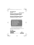
Rosemount 3051S Series
Pressure Transmitter Family
with FOUNDATION™ fieldbus Protocol
www.rosemount.com
Reference Manual
00809-0200-4801, Rev CA
July 2010
Rosemount 3051S
Rosemount 3051S Series
Pressure Transmitter with
FOUNDATION fieldbus Protocol
NOTICE
Read this manual before working with the product. For personal and system safety, and for
optimum product performance, make sure you thoroughly understand the contents before
installing, using, or maintaining this product.
Within the United States, Rosemount Inc. has two toll-free assistance numbers:
Customer Central
Technical support, quoting, and order-related questions.
1-800-999-9307 (7:00 am to 7:00 pm CST)
North American Response Center
Equipment service needs.
1-800-654-7768 (24 hours—includes Canada)
Outside of the United States, contact your local Emerson Process Management
representative.
The products described in this document are NOT designed for nuclear-qualified
applications. Using non-nuclear qualified products in applications that require
nuclear-qualified hardware or products may cause inaccurate readings.
For information on Rosemount nuclear-qualified products, contact your local Emerson
Process Management Sales Representative.
www.rosemount.com
Reference Manual
00809-0200-4801, Rev BA
July 2010
Rosemount 3051S
Table of Contents
SECTION 1
Introduction
Overview. . . . . . . . . . . . . . . . . . . . . . . . . . . . . . . . . . . . . . . . . . . . . . .
Using This Manual . . . . . . . . . . . . . . . . . . . . . . . . . . . . . . . . . . . . . . .
Service Support . . . . . . . . . . . . . . . . . . . . . . . . . . . . . . . . . . . . . . .
Device Description . . . . . . . . . . . . . . . . . . . . . . . . . . . . . . . . . . . . . . .
Node Address . . . . . . . . . . . . . . . . . . . . . . . . . . . . . . . . . . . . . . . . . . .
Tagging. . . . . . . . . . . . . . . . . . . . . . . . . . . . . . . . . . . . . . . . . . . . . . . .
Foundation fieldbus function blocks . . . . . . . . . . . . . . . . . . . . . . . . . .
SECTION 2
Installation
Overview. . . . . . . . . . . . . . . . . . . . . . . . . . . . . . . . . . . . . . . . . . . . . . . 2-1
Safety Messages . . . . . . . . . . . . . . . . . . . . . . . . . . . . . . . . . . . . . . . . 2-1
Warnings . . . . . . . . . . . . . . . . . . . . . . . . . . . . . . . . . . . . . . . . . . . . 2-1
Considerations . . . . . . . . . . . . . . . . . . . . . . . . . . . . . . . . . . . . . . . . . . 2-2
General . . . . . . . . . . . . . . . . . . . . . . . . . . . . . . . . . . . . . . . . . . . . . 2-2
Mechanical . . . . . . . . . . . . . . . . . . . . . . . . . . . . . . . . . . . . . . . . . . 2-2
Draft Range . . . . . . . . . . . . . . . . . . . . . . . . . . . . . . . . . . . . . . . . . . 2-3
Environmental . . . . . . . . . . . . . . . . . . . . . . . . . . . . . . . . . . . . . . . . 2-3
Installation Procedures . . . . . . . . . . . . . . . . . . . . . . . . . . . . . . . . . . . . 2-4
Mount the Transmitter . . . . . . . . . . . . . . . . . . . . . . . . . . . . . . . . . . 2-5
Process Connections. . . . . . . . . . . . . . . . . . . . . . . . . . . . . . . . . . 2-10
Consider Housing Rotation . . . . . . . . . . . . . . . . . . . . . . . . . . . . . 2-11
Configure Security . . . . . . . . . . . . . . . . . . . . . . . . . . . . . . . . . . . . 2-12
Simulate. . . . . . . . . . . . . . . . . . . . . . . . . . . . . . . . . . . . . . . . . . . . 2-12
Wiring . . . . . . . . . . . . . . . . . . . . . . . . . . . . . . . . . . . . . . . . . . . . . . . . 2-13
Transmitter Wiring . . . . . . . . . . . . . . . . . . . . . . . . . . . . . . . . . . . . 2-13
Transmitter Grounding. . . . . . . . . . . . . . . . . . . . . . . . . . . . . . . . . 2-14
Rotating the LCD Display . . . . . . . . . . . . . . . . . . . . . . . . . . . . . . . . . 2-14
Setting Units . . . . . . . . . . . . . . . . . . . . . . . . . . . . . . . . . . . . . . . . 2-15
Zeroing Transmitter . . . . . . . . . . . . . . . . . . . . . . . . . . . . . . . . . . . . . 2-15
Damping . . . . . . . . . . . . . . . . . . . . . . . . . . . . . . . . . . . . . . . . . . . 2-15
Rosemount 305, 306 and 304 Manifolds . . . . . . . . . . . . . . . . . . . . . 2-15
Rosemount 305 Integral Manifold Installation Procedure . . . . . . 2-16
Rosemount 306 In-Line Manifold Installation Procedure. . . . . . . 2-16
Rosemount 304 Conventional Manifold Installation Procedure. . 2-17
Manifold Operation . . . . . . . . . . . . . . . . . . . . . . . . . . . . . . . . . . . 2-18
SECTION 3
Configuration
Overview. . . . . . . . . . . . . . . . . . . . . . . . . . . . . . . . . . . . . . . . . . . . . . .
Safety Messages . . . . . . . . . . . . . . . . . . . . . . . . . . . . . . . . . . . . . . . .
Warnings . . . . . . . . . . . . . . . . . . . . . . . . . . . . . . . . . . . . . . . . . . . .
Device Capabilities . . . . . . . . . . . . . . . . . . . . . . . . . . . . . . . . . . . . . . .
Link Active Scheduler . . . . . . . . . . . . . . . . . . . . . . . . . . . . . . . . . .
Capabilities . . . . . . . . . . . . . . . . . . . . . . . . . . . . . . . . . . . . . . . . . .
General Block Information . . . . . . . . . . . . . . . . . . . . . . . . . . . . . . . . .
Modes . . . . . . . . . . . . . . . . . . . . . . . . . . . . . . . . . . . . . . . . . . . . . .
Block Instantiation . . . . . . . . . . . . . . . . . . . . . . . . . . . . . . . . . . . . .
Simulation . . . . . . . . . . . . . . . . . . . . . . . . . . . . . . . . . . . . . . . . . . .
Resource Block. . . . . . . . . . . . . . . . . . . . . . . . . . . . . . . . . . . . . . . . . .
FEATURES and FEATURES_SEL . . . . . . . . . . . . . . . . . . . . . . . .
MAX_NOTIFY . . . . . . . . . . . . . . . . . . . . . . . . . . . . . . . . . . . . . . . .
PlantWeb™ Alarms . . . . . . . . . . . . . . . . . . . . . . . . . . . . . . . . . . . .
1-1
1-1
1-2
1-2
1-2
1-2
1-3
3-1
3-1
3-1
3-2
3-2
3-2
3-3
3-3
3-4
3-4
3-4
3-4
3-5
3-6
TOC-1
Reference Manual
00809-0200-4801, Rev BA
July 2010
Rosemount 3051S
Analog Input (AI) Function Block . . . . . . . . . . . . . . . . . . . . . . . . . . . . 3-8
Configure the AI block . . . . . . . . . . . . . . . . . . . . . . . . . . . . . . . . . . 3-8
Configuration Examples . . . . . . . . . . . . . . . . . . . . . . . . . . . . . . . 3-11
Pressure transmitter . . . . . . . . . . . . . . . . . . . . . . . . . . . . . . . . . . 3-11
Pressure transmitter used to measure level in an open tank . . . 3-11
Differential pressure transmitter to measure flow . . . . . . . . . . . . 3-13
Filtering . . . . . . . . . . . . . . . . . . . . . . . . . . . . . . . . . . . . . . . . . . . . 3-14
Low Cutoff . . . . . . . . . . . . . . . . . . . . . . . . . . . . . . . . . . . . . . . . . . 3-14
Process Alarms . . . . . . . . . . . . . . . . . . . . . . . . . . . . . . . . . . . . . . 3-15
Alarm Priority . . . . . . . . . . . . . . . . . . . . . . . . . . . . . . . . . . . . . . . . 3-15
Status Options . . . . . . . . . . . . . . . . . . . . . . . . . . . . . . . . . . . . . . . 3-15
Advanced Features . . . . . . . . . . . . . . . . . . . . . . . . . . . . . . . . . . . 3-16
Multiple Analog Input (MAI) Function Block . . . . . . . . . . . . . . . . . . . 3-16
LCD Transducer Block . . . . . . . . . . . . . . . . . . . . . . . . . . . . . . . . . . . 3-17
Custom Meter Configuration . . . . . . . . . . . . . . . . . . . . . . . . . . . . 3-17
Display bar graph . . . . . . . . . . . . . . . . . . . . . . . . . . . . . . . . . . . . 3-19
Mass Flow. . . . . . . . . . . . . . . . . . . . . . . . . . . . . . . . . . . . . . . . . . . . . 3-20
Engineering Assistant Software . . . . . . . . . . . . . . . . . . . . . . . . . . . . 3-20
Installation and Setup . . . . . . . . . . . . . . . . . . . . . . . . . . . . . . . . . 3-20
SECTION 4
Operation and
Maintenance
Overview. . . . . . . . . . . . . . . . . . . . . . . . . . . . . . . . . . . . . . . . . . . . . . .
Safety Messages . . . . . . . . . . . . . . . . . . . . . . . . . . . . . . . . . . . . . . . .
Warnings . . . . . . . . . . . . . . . . . . . . . . . . . . . . . . . . . . . . . . . . . .
Status . . . . . . . . . . . . . . . . . . . . . . . . . . . . . . . . . . . . . . . . . . . . . . . . .
Licensing Optional Blocks. . . . . . . . . . . . . . . . . . . . . . . . . . . . . . . . . .
Master Reset Method . . . . . . . . . . . . . . . . . . . . . . . . . . . . . . . . . .
Simulation . . . . . . . . . . . . . . . . . . . . . . . . . . . . . . . . . . . . . . . . . . .
Calibration. . . . . . . . . . . . . . . . . . . . . . . . . . . . . . . . . . . . . . . . . . . . . .
Sensor Calibration, Upper and Lower Trim Methods . . . . . . . . . .
Sensor Calibration, Zero Trim Method . . . . . . . . . . . . . . . . . . . . .
Factory Trim Recall Method . . . . . . . . . . . . . . . . . . . . . . . . . . . . .
SECTION 5
Troubleshooting
Overview. . . . . . . . . . . . . . . . . . . . . . . . . . . . . . . . . . . . . . . . . . . . . . . 5-1
Safety Messages . . . . . . . . . . . . . . . . . . . . . . . . . . . . . . . . . . . . . . . . 5-1
Warnings . . . . . . . . . . . . . . . . . . . . . . . . . . . . . . . . . . . . . . . . . . . . 5-1
Troubleshooting Guides . . . . . . . . . . . . . . . . . . . . . . . . . . . . . . . . . . . 5-2
Resource Block. . . . . . . . . . . . . . . . . . . . . . . . . . . . . . . . . . . . . . . . . . 5-5
Sensor Transducer Block . . . . . . . . . . . . . . . . . . . . . . . . . . . . . . . . . . 5-6
Analog Input (AI) Function Block . . . . . . . . . . . . . . . . . . . . . . . . . . . . 5-7
MAI Block Troubleshooting . . . . . . . . . . . . . . . . . . . . . . . . . . . . . . 5-7
LCD Transducer block . . . . . . . . . . . . . . . . . . . . . . . . . . . . . . . . . . . . 5-8
Advanced Diagnostics Transducer Block (ADB) . . . . . . . . . . . . . . . . 5-9
PlantWeb Alerts . . . . . . . . . . . . . . . . . . . . . . . . . . . . . . . . . . . . . . . . 5-10
4-1
4-1
4-1
4-2
4-2
4-3
4-3
4-4
4-4
4-4
4-5
TOC-2
Reference Manual
00809-0200-4801, Rev BA
July 2010
Rosemount 3051S
SECTION 6
Advanced
Pressure
Diagnostics for
FOUNDATION
fieldbus
Overview. . . . . . . . . . . . . . . . . . . . . . . . . . . . . . . . . . . . . . . . . . . . . . . 6-1
Statistical Process Monitoring Technology . . . . . . . . . . . . . . . . . . . . . 6-2
SPM Functionality . . . . . . . . . . . . . . . . . . . . . . . . . . . . . . . . . . . . . 6-4
SPM Configuration and Operation . . . . . . . . . . . . . . . . . . . . . . . . . . . 6-6
SPM Configuration for Monitoring Pressure . . . . . . . . . . . . . . . . . 6-6
SPM Configuration for Monitoring Other Process Variables . . . . . 6-7
Other SPM Settings. . . . . . . . . . . . . . . . . . . . . . . . . . . . . . . . . . . . 6-7
Configuration of Alerts . . . . . . . . . . . . . . . . . . . . . . . . . . . . . . . . . . 6-8
SPM Operations . . . . . . . . . . . . . . . . . . . . . . . . . . . . . . . . . . . . . . 6-9
PlantWeb Alert. . . . . . . . . . . . . . . . . . . . . . . . . . . . . . . . . . . . . . . 6-10
Trending Statistical Values in Control System. . . . . . . . . . . . . . . 6-10
SPM Configuration with EDDL . . . . . . . . . . . . . . . . . . . . . . . . . . 6-11
Example Configuration of SPM using Function Block . . . . . . . . . 6-12
EDDL Trending of Mean and Standard Deviation . . . . . . . . . . . . 6-14
Trending SPM Data in DeltaV . . . . . . . . . . . . . . . . . . . . . . . . . . . 6-14
Plugged Impulse Line Detection Technology . . . . . . . . . . . . . . . . . . 6-17
Introduction . . . . . . . . . . . . . . . . . . . . . . . . . . . . . . . . . . . . . . . . . 6-17
Plugged Impulse Line Physics. . . . . . . . . . . . . . . . . . . . . . . . . . . 6-18
Plugged Line Detection Factors . . . . . . . . . . . . . . . . . . . . . . . . . 6-20
Plugged Impulse Line (PIL) Functionality . . . . . . . . . . . . . . . . . . 6-22
Configuration of Plugged Impulse Line Detection. . . . . . . . . . . . . . . 6-25
Basic Configuration . . . . . . . . . . . . . . . . . . . . . . . . . . . . . . . . . . . 6-25
Configuration of Detection Sensitivity . . . . . . . . . . . . . . . . . . . . . 6-26
Determining the Detection Sensitivity . . . . . . . . . . . . . . . . . . . . . 6-27
Advanced PIL Configuration . . . . . . . . . . . . . . . . . . . . . . . . . . . . 6-29
PIL Operation . . . . . . . . . . . . . . . . . . . . . . . . . . . . . . . . . . . . . . . 6-30
Plugged Impulse Line Configuration in EDDL . . . . . . . . . . . . . . . 6-31
Viewing the Indication of a Plugged Impulse Line . . . . . . . . . . . . 6-31
APPENDIX A
Foundation
fieldbus Block
Information
Overview. . . . . . . . . . . . . . . . . . . . . . . . . . . . . . . . . . . . . . . . . . . . . . . A-1
Resource Block. . . . . . . . . . . . . . . . . . . . . . . . . . . . . . . . . . . . . . . . . . A-1
Sensor Transducer Block . . . . . . . . . . . . . . . . . . . . . . . . . . . . . . . . . . A-7
Analog Input (AI) Function Block . . . . . . . . . . . . . . . . . . . . . . . . . . . . A-9
AI Parameter Table . . . . . . . . . . . . . . . . . . . . . . . . . . . . . . . . . . . A-10
LCD Display Transducer Block. . . . . . . . . . . . . . . . . . . . . . . . . . . . . A-13
Advanced Diagnostics Transducer Block (ADB) . . . . . . . . . . . . . . . A-15
APPENDIX B
Specifications and
Reference Data
Performance Specifications . . . . . . . . . . . . . . . . . . . . . . . . . . . . . . . .
Conformance to Specification (±3s (Sigma)). . . . . . . . . . . . . . . . .
Reference Accuracy . . . . . . . . . . . . . . . . . . . . . . . . . . . . . . . . . . .
Transmitter Total Performance . . . . . . . . . . . . . . . . . . . . . . . . . . .
MultiVariable Flow Performance . . . . . . . . . . . . . . . . . . . . . . . . . .
Uncompensated Flow Performance . . . . . . . . . . . . . . . . . . . . . . .
Long Term Stability . . . . . . . . . . . . . . . . . . . . . . . . . . . . . . . . . . . .
Warranty(1). . . . . . . . . . . . . . . . . . . . . . . . . . . . . . . . . . . . . . . . . . .
Dynamic Performance . . . . . . . . . . . . . . . . . . . . . . . . . . . . . . . . . .
Ambient Temperature Effect . . . . . . . . . . . . . . . . . . . . . . . . . . . . .
Line Pressure Effect . . . . . . . . . . . . . . . . . . . . . . . . . . . . . . . . . . .
Mounting Position Effects . . . . . . . . . . . . . . . . . . . . . . . . . . . . . . .
Vibration Effect . . . . . . . . . . . . . . . . . . . . . . . . . . . . . . . . . . . . . . .
Power Supply Effect . . . . . . . . . . . . . . . . . . . . . . . . . . . . . . . . . . .
Electromagnetic Compatibility (EMC) . . . . . . . . . . . . . . . . . . . . . .
Transient Protection (Option T1) . . . . . . . . . . . . . . . . . . . . . . . . . .
B-1
B-1
B-2
B-3
B-4
B-5
B-5
B-6
B-6
B-7
B-8
B-8
B-9
B-9
B-9
B-9
TOC-3
Reference Manual
00809-0200-4801, Rev BA
July 2010
Rosemount 3051S
Functional Specifications . . . . . . . . . . . . . . . . . . . . . . . . . . . . . . . . .
Range and Sensor Limits . . . . . . . . . . . . . . . . . . . . . . . . . . . . . .
Minimum Span Limits . . . . . . . . . . . . . . . . . . . . . . . . . . . . . . . . .
Overpressure Limits . . . . . . . . . . . . . . . . . . . . . . . . . . . . . . . . . .
Static Pressure Limits . . . . . . . . . . . . . . . . . . . . . . . . . . . . . . . . .
Burst Pressure Limits . . . . . . . . . . . . . . . . . . . . . . . . . . . . . . . . .
Temperature Limits . . . . . . . . . . . . . . . . . . . . . . . . . . . . . . . . . . .
Humidity Limits . . . . . . . . . . . . . . . . . . . . . . . . . . . . . . . . . . . . . .
Turn-On Time . . . . . . . . . . . . . . . . . . . . . . . . . . . . . . . . . . . . . . .
Volumetric Displacement. . . . . . . . . . . . . . . . . . . . . . . . . . . . . . .
Damping(1) . . . . . . . . . . . . . . . . . . . . . . . . . . . . . . . . . . . . . . . . . .
Failure Mode Alarm . . . . . . . . . . . . . . . . . . . . . . . . . . . . . . . . . . .
Safety-Certified Transmitter Failure Values(2) . . . . . . . . . . . . . . .
Physical Specifications . . . . . . . . . . . . . . . . . . . . . . . . . . . . . . . . . . .
Electrical Connections . . . . . . . . . . . . . . . . . . . . . . . . . . . . . . . . .
Process Connections. . . . . . . . . . . . . . . . . . . . . . . . . . . . . . . . . .
Process-Wetted Parts . . . . . . . . . . . . . . . . . . . . . . . . . . . . . . . . .
Non-Wetted Parts . . . . . . . . . . . . . . . . . . . . . . . . . . . . . . . . . . . .
Shipping Weights. . . . . . . . . . . . . . . . . . . . . . . . . . . . . . . . . . . . .
Dimensional Drawings . . . . . . . . . . . . . . . . . . . . . . . . . . . . . . . . . . .
Accessories . . . . . . . . . . . . . . . . . . . . . . . . . . . . . . . . . . . . . . . . . . .
Ordering Information. . . . . . . . . . . . . . . . . . . . . . . . . . . . . . . . . . . . .
Exploded view Diagram . . . . . . . . . . . . . . . . . . . . . . . . . . . . . . . . . .
Spare Parts. . . . . . . . . . . . . . . . . . . . . . . . . . . . . . . . . . . . . . . . . . . .
B-10
B-10
B-11
B-15
B-16
B-16
B-17
B-18
B-18
B-18
B-18
B-18
B-18
B-18
B-18
B-19
B-19
B-20
B-21
B-23
B-31
B-33
B-51
B-52
APPENDIX C
Product
Certifications
Approved Manufacturing Locations . . . . . . . . . . . . . . . . . . . . . . . . . . C-1
Ordinary Location Certification for FM . . . . . . . . . . . . . . . . . . . . . . . . C-1
European Directive Information . . . . . . . . . . . . . . . . . . . . . . . . . . . . . C-1
Hazardous Locations Certifications . . . . . . . . . . . . . . . . . . . . . . . . . . C-2
Installation Drawings. . . . . . . . . . . . . . . . . . . . . . . . . . . . . . . . . . . . . . C-8
Factory Mutual (FM) . . . . . . . . . . . . . . . . . . . . . . . . . . . . . . . . . . . C-8
Canadian Standards Association (CSA) . . . . . . . . . . . . . . . . . . . C-25
KEMA . . . . . . . . . . . . . . . . . . . . . . . . . . . . . . . . . . . . . . . . . . . . . C-38
European ATEX Directive Information . . . . . . . . . . . . . . . . . . . . . . . C-41
CENELEC/BASEEFA . . . . . . . . . . . . . . . . . . . . . . . . . . . . . . . . . C-41
CENELEC/KEMA Flameproof . . . . . . . . . . . . . . . . . . . . . . . . . . . . . C-43
APPENDIX D
3051S FOUNDATION
fieldbus Revision
23 Release
New Function Blocks . . . . . . . . . . . . . . . . . . . . . . . . . . . . . . . . . . . . . D-1
New Functionality . . . . . . . . . . . . . . . . . . . . . . . . . . . . . . . . . . . . . . . . D-2
TOC-4
Reference Manual
00809-0200-4801, Rev CA
July 2010
Rosemount 3051S
Section 1
Introduction
OVERVIEW
This manual is for the 3051S Series Pressure Transmitter with FOUNDATION
fieldbus communications. This transmitter’s scalable architecture allows
putting a FOUNDATION fieldbus output board with any performance class
3051S supermodule and any of its process connections.
This manual only describes the topics required for installation, operation,
configuration, and troubleshooting the FOUNDATION fieldbus transmitter.
For Rosemount 3051S with HART, see Manual 00809-0100-4801.
USING THIS MANUAL
The sections in this manual provide information on configuring,
troubleshooting, operating and maintaining Rosemount 3051S Series
Pressure Transmitters specifically for FOUNDATION fieldbus protocol.
The sections in this manual are organized as follows:
•
Section 2: Installation contains mechanical and electrical installation
instructions, and field upgrade options.
•
Section 3: Configuration provides instruction on configuration of the
Rosemount 3051S Series transmitters with fieldbus protocol.
Information on software functions, configuration parameters, and other
variables are also included.
•
Section 4: Operation and Maintenance contains operation and
maintenance techniques.
•
Section 5: Troubleshooting provides troubleshooting techniques for
the most common operating problems.
•
Appendix A: Foundation Fieldbus Block Information supplies
reference block information such as parameter tables.
•
Appendix B: Specifications and Reference Data supplies reference
and specification data, as well as ordering information.
•
Appendix C: Product Certifications contains intrinsic safety approval
information, European ATEX directive information, and approval
drawings.
•
Appendix D: 3051S Foundation Fieldbus Revision 23 Release
contains new function block and new functionality information.
1-1
Reference Manual
00809-0200-4801, Rev CA
July 2010
Rosemount 3051S
Service Support
To expedite the return process outside of the United States, contact the
nearest Emerson Process Management representative.
Within the United States, call the Rosemount National Response Center using
the 1-800-654-RSMT (7768) toll-free number. This center, available 24 hours
a day, will assist you with any needed information or materials.
The center will ask for product model and serial numbers, and will provide a
Return Material Authorization (RMA) number. The center will also ask for the
process material to which the product was last exposed.
Individuals who handle products exposed to a hazardous substance can avoid injury if
they are informed of and understand the hazard. If the product being returned was
exposed to a hazardous substance as defined by OSHA, a copy of the required Material
Safety Data Sheet (MSDS) for each hazardous substance identified must be included
with the returned goods.
Rosemount National Response Center representatives will explain the
additional information and procedures necessary to return goods exposed to
hazardous substances.
DEVICE DESCRIPTION
Before configuring the device, ensure the host has the appropriate Device
Description file revision for this device. The device descriptor can be found on
www.fieldbus.org. The initial release of the Rosemount 3051S with
FOUNDATION fieldbus protocol is device revision 20. This manual is for revision
23.
NODE ADDRESS
The transmitter is shipped at a temporary (248) address. This will enable
FOUNDATION fieldbus host systems to automatically recognize the device and
move it to a permanent address.
TAGGING
Commissioning Tag
The 3051S has been supplied with a removable commissioning tag that
contains both the Device ID (the unique code that identifies a particular device
in the absence of a device tag) and a space to record the device tag
(PD_TAG) (the operational identification for the device as defined by the
Piping and Instrumentation Diagram (P&ID)).
When commissioning more than one device on a fieldbus segment, it can be
difficult to identify which device is at a particular location. The removable tag,
provided with the transmitter, can aid in this process by linking the Device ID
to its physical location. The installer should note the physical location of the
transmitter on both the upper and lower location of the commissioning tag.
The bottom portion should be torn off for each device on the segment and
used for commissioning the segment in the control system.
1-2
Reference Manual
00809-0200-4801, Rev CA
July 2010
Rosemount 3051S
Figure 1-1. Commissioning Tag
COMMISSIONING LABEL
Device ID
Device Tag
to denote
physical
location
DEVICE ID:
00115113051032003161928-030016245
PD TAG:
007138842
REVISION: 7.2
REVISION: 7.2
S/N UNIT #: 0071358842
DEVICE ID:
00115113051032003161928-030016245
PD TAG:
007138842
Transmitter Tag
If permanent tag is ordered:
• Transmitter is tagged in accordance with customer requirements
• Tag is permanently attached to the transmitter
Software (PD_TAG)
• If permanent tag is ordered, the PD Tag contains the permanent tag
information up to 30 characters
• If permanent tag is NOT ordered, the PD Tag contains the transmitter
serial number
FOUNDATION FIELDBUS
FUNCTION BLOCKS
For reference information on the Resource, Sensor Transducer, AI, LCD
Transducer, Advanced Diagnostics Transducer blocks refer to “Foundation
Fieldbus Block Information” on page A-1. Reference information on the ISEL,
INT, ARTH, SGCR and PID blocks can be found in the Function Block manual
document number 00809-0100-4783.
Resource Block
The Resource block contains diagnostic, hardware and electronics
information. There are no linkable inputs or outputs to the Resource Block.
Sensor Transducer Block
The Sensor Transducer Block contains sensor information including the
sensor diagnostics and the ability to trim the pressure sensor or recall factory
calibration.
LCD Transducer Block
The LCD Transducer Block is used to configure the LCD meter.
Advanced Diagnostics Transducer Block
The Advanced Diagnostics Transducer Block is optionally licensed. It will be
licensed on a new transmitter if the D01 option is ordered or can be licensed
in the field via a licensing code. Please contact your local sales person on
how to acquire a license for a field upgrade.
This block allows a user to view, configure and monitor the plugged impulse
line detection and statistical process monitoring diagnostics.
1-3
Reference Manual
00809-0200-4801, Rev CA
July 2010
Rosemount 3051S
Analog Input Block
The Analog Input (AI) Function Block processes the measurements from the
sensor and makes them available to other function blocks. The output value
from the AI block is in engineering units and contains a status indicating the
quality of the measurement. The AI block is widely used for scaling
functionality.
Input Selector Block
The Input Selector (ISEL) Function Block can be used to select the first good,
Hot Backup, maximum, minimum, or average of as many as eight input
values and place it at the output. The block supports signal status
propagation.
Integrator Block
The Integrator (INT) Function Block integrates one or two variables over time.
The block compares the integrated or accumulated value to pre-trip and trip
limits and generates discrete output signals when the limits are reached.
Arithmetic Block
The Arithmetic (ARTH) Function Block provides the ability to configure a
range extension function for a primary input. It can also be used to compute
nine different arithmetic functions.
Signal Characterizer Block
The Signal Characterizer (SGCR) Function Block characterizes or
approximates any function that defines an input/output relationship. The
function is defined by configuring as many as twenty X,Y coordinates. The
block interpolates an output value for a given input value using the curve
defined by the configured coordinates. Two separate analog input signals can
be processed simultaneously to give two corresponding separate output
values using the same defined curve.
PID Block
The PID Function Block combines all of the necessary logic to perform
proportional/integral/derivative (PID) control. The block supports mode
control, signal scaling and limiting, feed forward control, override tracking,
alarm limit detection, and signal status propagation.
The block supports two forms of the PID equation: Standard and Series. You
can choose the appropriate equation using the MATHFORM parameter. The
Standard ISA PID equation is the default selection.
Integrator Block
The Integrator Block is used as a totalizer. This block will accept up to two
inputs, has six options how to totalize the inputs, and two trip outputs.
Control Selector Block
The Control Selector Function Block selects one of two or three inputs to be
the output. The inputs are normally connected to the outputs of PID or other
function blocks. One of the inputs would be considered Normal and the other
two overrides.
1-4
Reference Manual
00809-0200-4801, Rev CA
July 2010
Rosemount 3051S
Output Splitter Block
The Output Splitter Function Block provides the capability to drive two control
outputs from a single input. It takes the output of one PID or other control
block to control two valves or other actuators.
Multiple Analog Input Block
The Multiple Analog Input Block allows for up to 8 variables to be published in
one macro cycle. The primary purpose of this block to publish data that is
channeled to it from the Advanced Diagnostic Block.
Analog Output Block
The Analog Output Function Block accepts an output value from a field device
and assigns it to a specified I/O channel.
Mass Flow Transducer Block
The Mass Flow Function Block is an optionally licensed transducer block (H01
option) that will output a fully compensated mass flow value. It accepts
Differential pressure, gage or absolute pressure and temperature inputs and
then uses the flow calculation equation generated by the Engineering
Assistant configuration tool to derive the output. The user can enter a fixed
temperature if a temperature device is not available.
Table 1-1. Block Index Numbers
Block Name
Revision 20
Revision 23
Advanced Diagnostic Block
Analog Input Block
PID Block
Input Selector Block
Signal Characterizer Block
Arithmetic Block
Integrator Block
Multiple Analog Input Block
Control Selector Block
Output Splitter Block
Analog Output Block
Mass Flow
1300
1400, 1500
1600
1700
1800
1900
2000
1300
1400, 1500, 2100, 2200
1600
1700, 2400
1800
1900
2000
2300
2500
2600
2700, 2800
2900
1-5
Reference Manual
Rosemount 3051S
1-6
00809-0200-4801, Rev CA
July 2010
Reference Manual
00809-0200-4801, Rev CA
July 2010
Section 2
Rosemount 3051S Series
Installation
Overview . . . . . . . . . . . . . . . . . . . . . . . . . . . . . . . . . . . . . . . page 2-1
Safety Messages . . . . . . . . . . . . . . . . . . . . . . . . . . . . . . . . . page 2-1
Considerations . . . . . . . . . . . . . . . . . . . . . . . . . . . . . . . . . . page 2-2
Installation Procedures . . . . . . . . . . . . . . . . . . . . . . . . . . . page 2-4
Wiring . . . . . . . . . . . . . . . . . . . . . . . . . . . . . . . . . . . . . . . . . . page 2-13
Rotating the LCD Display . . . . . . . . . . . . . . . . . . . . . . . . . . page 2-14
Zeroing Transmitter . . . . . . . . . . . . . . . . . . . . . . . . . . . . . . page 2-15
Rosemount 305, 306 and 304 Manifolds . . . . . . . . . . . . . . page 2-15
OVERVIEW
The information in this section covers installation considerations for 3051S
with protocol. A Quick Installation Guide for this product (document number
00825-0200-4801) is shipped with every transmitter to describe basic
installation, wiring, and startup procedures. Dimensional drawings for each
Rosemount 3051S variation and mounting configuration are included in
Appendix B: Specifications and Reference Data.
SAFETY MESSAGES
Procedures and instructions in this section may require special precautions to
ensure the safety of the personnel performing the operation. Information that
raises potential safety issues is indicated with a warning symbol (
). Refer
to the following safety messages before performing an operation preceded by
this symbol.
Warnings
Explosions can result in death or serious injury.
www.rosemount.com
•
Do not remove the transmitter covers in explosive environments when the
circuit is live.
•
Fully engage both transmitter covers to meet explosion-proof requirements.
•
Before connecting a communicator in an explosive atmosphere, make sure the
instruments in the loop are installed in accordance with intrinsically safe or
non-incendive field wiring practices.
•
Verify that the operating atmosphere of the transmitter is consistent with the
appropriate hazardous locations certifications.
Reference Manual
00809-0200-4801, Rev CA
July 2010
Rosemount 3051S Series
Electrical shock can result in death or serious injury.
•
Avoid contact with the leads and terminals.
Process leaks could result in death or serious injury.
•
Install and tighten all four flange bolts before applying pressure.
•
Do not attempt to loosen or remove flange bolts while the transmitter is
in service.
Replacement equipment or spare parts not approved by Rosemount Inc. for use
as spare parts could reduce the pressure retaining capabilities of the transmitter
and may render the instrument dangerous.
•
Use only bolts supplied or sold by Rosemount Inc. as spare parts.
Improper assembly of manifolds to traditional flange can damage SuperModule™
Platform.
•
For safe assembly of manifold to traditional flange, bolts must break back
plane of flange web (i.e., bolt hole) but must not contact module housing.
Upper and lower unit labeling must match exactly to maintain hazardous
location approvals.
•
When upgrading, it is imperative that approval codes match between the
SuperModule and the electronics housing.
CONSIDERATIONS
General
Measurement performance depends upon proper installation of the
transmitter and impulse piping. Mount the transmitter close to the process and
use minimum piping to achieve best performance. Also, consider the need for
easy access, personnel safety, practical field calibration, and a suitable
transmitter environment. Install the transmitter to minimize vibration, shock,
and temperature fluctuation.
IMPORTANT
Install the enclosed pipe plug (found in the box) in the unused conduit
opening. For straight threads, a minimum of 6 threads must be engaged. For
tapered threads, install the plug wrench-tight.
For material compatibility considerations, see document number
00816-0100-3045 on www.rosemount.com.
Mechanical
NOTE
For steam service or for applications with process temperatures greater than
the limits of the transmitter, do not blow down impulse piping through the
transmitter. Flush lines with the blocking valves closed and refill lines with
water before resuming measurement.
NOTE
When the transmitter is mounted on its side, position the Coplanar flange to
ensure proper venting or draining. Mount the flange as shown in Figure 2-2 on
page 2-9, keeping drain/vent connections on the bottom for gas service and
on the top for liquid service.
2-2
Reference Manual
00809-0200-4801, Rev CA
July 2010
Draft Range
Rosemount 3051S Series
Installation
For the 3051S_CD0 draft range pressure transmitter, it is best to mount the
transmitter with the isolators parallel to the ground. Installing the transmitter in
this way reduces oil mounting effect and provides for optimal temperature
performance.
Be sure the transmitter is securely mounted. Tilting of the transmitter may
cause a zero shift in the transmitter output.
Reducing Process Noise
There are two recommended methods of reducing process noise: output
damping and, in gage applications, reference side filtering.
Reference Side Filtering
In gage applications it is important to minimize fluctuations in atmospheric
pressure to which the low side isolator is exposed. One method of reducing
fluctuations in atmospheric pressure is to attach a length of tubing to the
reference side of the transmitter to act as a pressure buffer.
Another method is to plumb the reference side to a chamber that has a small
vent to atmosphere. If multiple draft transmitters are being used in an
application, the reference side of each device can be plumbed to a chamber
to achieve a common gage reference.
Environmental
Access requirements and cover installation on page 2-4 can help optimize
transmitter performance. Mount the transmitter to minimize ambient
temperature changes, vibration, mechanical shock, and to avoid external
contact with corrosive materials. Appendix B: Specifications and Reference
Data lists temperature operating limits.
2-3
Reference Manual
Rosemount 3051S Series
INSTALLATION
PROCEDURES
00809-0200-4801, Rev CA
July 2010
For dimensional drawing information refer to Appendix B: Specifications and
Reference Data on page B-15.
Process Flange Orientation
Mount the process flanges with sufficient clearance for process connections.
For safety reasons, place the drain/vent valves so the process fluid is directed
away from possible human contact when the vents are used. In addition,
consider the need for a testing or calibration input.
Housing Rotation
See “Consider Housing Rotation” on page 2-11.
Terminal Side of Electronics Housing
Mount the transmitter so the terminal side is accessible. Clearance of 0.75 in.
(19 mm) is required for cover removal. Use a conduit plug in the unused
conduit opening.
Circuit Side of Electronics Housing
Provide 0.75 in. (19 mm) of clearance for units with out an LCD display. Three
inches of clearance is required for cover removal if a meter is installed.
Cover Installation
Always ensure a proper seal by installing the electronics housing cover(s) so
that metal contacts metal. Use Rosemount O-rings.
Cover Jam Screw
For transmitter housings shipped with a cover jam screw, as shown in
Figure 2-1, the screw should be properly installed once the transmitter has
been wired and powered up. The cover jam screw is intended to disallow the
removal of the transmitter cover in flameproof environments without the use of
tooling. Follow these steps to install the cover jam screw:
1. Verify that the cover jam screw is completely threaded into the housing.
2. Install the transmitter housing cover and verify that the cover is tight
against the housing.
3. Using an M4 hex wrench, loosen the jam screw until it contacts the
transmitter cover.
4. Turn the jam screw an additional 1/2 turn counterclockwise to secure the
cover. (Note: Application of excessive torque may strip the threads.)
5. Verify that the cover cannot be removed.
2-4
Reference Manual
00809-0200-4801, Rev CA
July 2010
Rosemount 3051S Series
Figure 2-1. Cover Jam Screw
PlantWeb® Housing
Junction Box Housing
Cover Jam
Screw
2X Cover Jam Screw
(1 per side)
Mount the Transmitter
Mounting Brackets
Facilitate mounting transmitter to a 2-in. pipe, or to a panel. The B4 Bracket
(SST) option is standard for use with the Coplanar and In-Line process
connections. “Coplanar Flange Mounting Configurations” on page B-17
shows bracket dimensions and mounting configurations for the B4 option.
Options B1–B3 and B7–B9 are sturdy, epoxy/polyester-painted brackets
designed for use with the traditional flange. The B1–B3 brackets have carbon
steel bolts, while the B7–B9 brackets have stainless steel bolts. The BA and
BC brackets and bolts are stainless steel. The B1/B7/BA and B3/B9/BC style
brackets support 2-inch pipe-mount installations, and the B2/B8 style brackets
support panel mounting.
Flange Bolts
The 3051S can be shipped with a Coplanar flange or a Traditional flange
installed with four 1.75-inch flange bolts. Mounting bolts and bolting
configurations for the Coplanar and Traditional flanges can be found on
page 2-7. Stainless steel bolts supplied by Emerson Process Management
are coated with a lubricant to ease installation. Carbon steel bolts do not
require lubrication. No additional lubricant should be applied when installing
either type of bolt. Bolts supplied by Emerson Process Management are
identified by their head markings:
B7M
Carbon Steel (CS) Head Markings
316
B8M
660
CL A
KM
Alloy 400 Head Marking
Stainless Steel (SST) Head Markings
F593_*
* The last digit in the F593_ head marking
may be any letter between A and M.
2-5
Reference Manual
00809-0200-4801, Rev CA
July 2010
Rosemount 3051S Series
Bolt Installation
Only use bolts supplied with the Rosemount 3051S or sold by Emerson
Process Management as spare parts. When installing the transmitter to
one of the optional mounting brackets, torque the bolts to 125 in-lb.
(0,9 N-m). Use the following bolt installation procedure:
1. Finger-tighten the bolts.
2. Torque the bolts to the initial torque value using a crossing pattern.
3. Torque the bolts to the final torque value using the same
crossing pattern.
Torque values for the flange and manifold adapter bolts are as follows:
Table 2-1. Bolt Installation
Torque Values
2-6
Bolt Material
Initial Torque Value
Final Torque Value
CS-ASTM-A445 Standard
316 SST—Option L4
ASTM-A-193-B7M—Option L5
Alloy 400 —Option L6
ASTM-A-453-660—Option L7
ASTM-A-193-B8M—Option L8
300 in.-lb (34 N-m)
150 in.-lb (17 N-m)
300 in.-lb (34 N-m)
300 in.-lb (34 N-m)
150 in.-lb (17 N-m)
150 in.-lb (17 N-m)
650 in.-lb (73 N-m)
300 in.-lb (34 N-m)
650 in.-lb (73 N-m)
650 in.-lb (73 N-m)
300 in.-lb (34 N-m)
300 in.-lb (34 N-m)
Reference Manual
00809-0200-4801, Rev CA
July 2010
Rosemount 3051S Series
GAGE/ABSOLUTE TRANSMITTER
DIFFERENTIAL TRANSMITTER
Drain/Vent
Plug
Drain/Vent
Drain/Vent
1.75 (44) x 4
1.75 (44) x 4
1.50 (38) x 4
1.50 (38) x 2
NOTE
Dimensions are in inches (millimeters).
Transmitter with
Flange Adapters
and Flange/ Adapter Bolts
Transmitter with
Flange Bolts
1.75 (44) x 4
2.88 (73) x 4
Description
Differential Pressure
Flange Bolts
Adapter Bolts
Flange/ Adapter Bolts
Gage/Absolute Pressure(2)
Flange Bolts
Adapter Bolts
Flange/ Adapter Bolts
Qty
Size in in. (mm)
4
4
4
1.75 (44)
1.50 (38)(1)
2.88 (73)
4
2
2
1.75 (44)
1.50 (38)(1)
2.88(73)
(1) DIN-compliant traditional flange requires 1.75 in. (44 mm) length adapter bolts.
(2) Rosemount 3051S In-line transmitters are direct mount and do not require bolts
for process connection.
2-7
Reference Manual
Rosemount 3051S Series
00809-0200-4801, Rev CA
July 2010
Impulse Piping
The piping between the process and the transmitter must accurately transfer
the pressure to obtain accurate measurements. There are five possible
sources of error: pressure transfer, leaks, friction loss (particularly if purging is
used), trapped gas in a liquid line, liquid in a gas line, density variations
between the legs, and plugged impulse piping.
The best location for the transmitter in relation to the process pipe depends on
the process itself. Use the following guidelines to determine transmitter
location and placement of impulse piping:
2-8
•
Keep impulse piping as short as possible.
•
For liquid service, slope the impulse piping at least 1 inch per foot
(8 cm per m) upward from the transmitter toward the
process connection.
•
For gas service, slope the impulse piping at least 1 inch per foot (8 cm
per m) downward from the transmitter toward the process connection.
•
Avoid high points in liquid lines and low points in gas lines.
•
Make sure both impulse legs are the same temperature.
•
Use impulse piping large enough to avoid friction effects and blockage.
•
Vent all gas from liquid piping legs.
•
When using a sealing fluid, fill both piping legs to the same level.
•
When purging, make the purge connection close to the process taps
and purge through equal lengths of the same size pipe. Avoid purging
through the transmitter.
•
Keep corrosive or hot (above 250 °F [121 °C]) process material out of
direct contact with the SuperModule and flanges.
•
Prevent sediment deposits in the impulse piping.
•
Keep the liquid head balanced on both legs of the impulse piping.
•
Avoid conditions that might allow process fluid to freeze within the
process flange.3
Reference Manual
00809-0200-4801, Rev CA
July 2010
Rosemount 3051S Series
Mounting Requirements
Impulse piping configurations depend on specific measurement conditions.
Refer to Figure 2-2 for examples of the following mounting configurations:
Liquid Flow Measurement
•
Place taps to the side of the line to prevent sediment deposits on the
process isolators.
•
Mount the transmitter beside or below the taps so gases vent into the
process line.
•
Mount drain/vent valve upward to allow gases to vent.
Gas Flow Measurement
•
Place taps in the top or side of the line.
•
Mount the transmitter beside or above the taps so to drain liquid into
the process line.
Steam Flow Measurement
•
Place taps to the side of the line.
•
Mount the transmitter below the taps to ensure that impulse piping will
remain filled with condensate.
•
In steam service above 250 °F (121 °C), fill impulse lines with water to
prevent steam from contacting the transmitter directly and to ensure
accurate measurement start-up.
NOTE
For steam or other elevated temperature services, it is important that
temperatures at the process connection do not exceed the transmitter’s
process temperature limits. See “Process Temperature Limits” on page B-11
for details.
Figure 2-2. Coplanar Installation
Examples
GAS OR LIQUID SERVICE
GAS SERVICE
STEAM SERVICE
FLOW
2-9
Reference Manual
00809-0200-4801, Rev CA
July 2010
Rosemount 3051S Series
Figure 2-3. In-Line Installation
Examples
Process Connections
GAS SERVICE
GAS OR LIQUID
SERVICE
LIQUID OR STEAM
SERVICE
3051S transmitter flange process connection size is 1/4–18 NPT. Flange
adapters with 1/2–14 NPT connections are available as the D2 option. Use
your plant-approved lubricant or sealant when making the process
connections. The process connections on the transmitter flange are on
21/8-inch (54 mm) centers to allow direct mounting to a three-valve or
five-valve manifold. Rotate one or both of the flange adapters to attain
connection centers of 2 inches (51 mm), 21/8 inches (54 mm), or 21/4 inches
(57 mm).
Install and tighten all four flange bolts before applying pressure to avoid
leakage. When properly installed, the flange bolts will protrude through the top
of the SuperModule housing. Do not attempt to loosen or remove the flange
bolts while the transmitter is in service.
To install adapters to a Coplanar flange, perform the following procedure:
1. Remove the flange bolts.
2. Leaving the flange in place, move the adapters into position with the
O-ring installed.
3. Clamp the adapters and the Coplanar flange to the transmitter module
using the longer of the bolts supplied.
4. Tighten the bolts. Refer to Table 2-1 on page 2-6 for torque
specifications.
2-10
Reference Manual
00809-0200-4801, Rev CA
July 2010
Rosemount 3051S Series
Failure to install proper flange adapter O-rings can cause process leaks, which can
result in death or serious injury.
The two flange adapters are distinguished by unique O-ring grooves. Only use the
O-ring that is designed for its specific flange adapter, as shown below.
ROSEMOUNT 3051S/ 3051/3001/3095/2024
Flange Adapter
O-ring
3051S
3051C
2024
PTFE Based
Elastomer
ROSEMOUNT 1151
Flange Adapter
O-ring
PTFE
Elastomer
Refer to the Spare Parts list in Appendix B: Specifications and Reference Data for the
correct part numbers of the flange adapters and O-rings designed for 3051S
transmitters.
Whenever you remove flanges or adapters, visually inspect the PTFE
O-rings. Replace them if there are any signs of damage, such as nicks or
cuts. If you replace the O-rings, re-torque the flange bolts after installation to
compensate for cold flow. Refer to the process sensor body reassembly
procedure in Section 5 Troubleshooting on page 5-6.
Consider Housing
Rotation
The housing can be rotated to improve field access to wiring or to better view
the optional LCD display. Perform the following procedure:
Figure 2-4. Housings
PlantWeb® Housing
Junction Box Housing
Housing Rotation Set
Screw (3/32-inch)
2-11
Reference Manual
Rosemount 3051S Series
00809-0200-4801, Rev CA
July 2010
1. Loosen the housing rotation set screw.
2. First rotate the housing clockwise to the desired location. If the desired
location cannot be achieved due to thread limit, rotate the housing
counter clockwise to the desired location (up to 360° from thread limit).
3. Retighten the housing rotation set screw.
In addition to housing rotation, the optional LCD display can be rotated in
90-degree increments by squeezing the two tabs, pulling out, rotating and
snapping back into place.
NOTE
If LCD pins are inadvertently removed from the interface board, carefully
re-insert the pins before snapping the LCD display back into place.
Configure Security
The 3051S FOUNDATION fieldbus transmitter has a hierarchy of security. The
SECURITY switch located on the electronics provides the highest level of
security. In the ON position, all writes to the transmitter are disabled.
Simulate
The SIMULATE switch is located on the Electronics. It is used in conjunction
with the transmitter simulate software to simulate process variables and/or
alerts and alarms. To simulate variables and/or alerts and alarms, the
SIMULATE switch must be moved to the ENABLE position and the software
enabled through the host. To disable simulation, the switch must be in the
DISABLE position.
2-12
Reference Manual
00809-0200-4801, Rev CA
July 2010
Rosemount 3051S Series
NOTE
It is important to know that Simulate is enabled only when the hardware
senses the switch changing from DISABLE to ENABLE. If the power is
removed with the switch in ENABLE, Simulate is not enabled. You must move
the switch from ENABLE to DISABLE and then back to ENABLE to be able to
use the Simulate software.
WIRING
Transmitter Wiring
Wiring and power supply requirements can be dependent upon the approval
certification. As with all FOUNDATION fieldbus requirements, a conditioned
power supply and terminating resistors are required for proper operation. The
standard 3051S pressure transmitter terminal block is pictured below. The
terminals are not polarity sensitive. The transmitter requires 9-32 Vdc to
operate. Type A FOUNDATION fieldbus wiring 18 awg twisted shielded pair is
recommended.
NOTE
Avoid running instrument cable next to power cables in cable trays or near
heavy electrical equipment.
It is important that the instrument cable shield be:
- trimmed close and insulated from touching the transmitter housing
- continuously connected throughout the segment
- connected to a good earth ground at the power supply end
Figure 2-5.
Minimize Distance
Ground for
Transient
Protection
Trim shield and
insulate
DP
Connect Shield Back
to the Power Supply
Ground
Insulate
Shield
FIELDBUS WIRING
2-13
Reference Manual
00809-0200-4801, Rev CA
July 2010
Rosemount 3051S Series
Transmitter Grounding
Always ground the transmitter case in accordance with national and local
electrical codes. A ground can be connected to the 3051S Transmitter either
by an external ground lug or the internal ground lug. Both options can be seen
in Figure 2-6.
Figure 2-6.
3051S Inline SuperModule
External Ground
Connection
3051S Inline SuperModule
External Ground
Connection
3051S Internal
Ground Connection
The most effective transmitter case grounding method is a direct connection
to earth ground with minimal (< 1 ) impedance.
NOTE
Grounding the transmitter case using the threaded conduit connection may
not provide a sufficient ground. The transient protection terminal block (Option
Code T1) will not provide transient protection unless the transmitter case is
properly grounded. Use the above guidelines to ground the transmitter case.
Do not run transient protection ground wire with signal wiring; the ground wire
may carry excessive current if a lightning strike occurs.
ROTATING THE
LCD DISPLAY
Transmitters ordered with the LCD display will be shipped with the display
installed. The display can be rotated in 90 degree increments. To rotate the
display:
1. Ensure the power is removed from the transmitter.
2. Remove the cover to expose the LCD Display.
3. Squeeze the two tabs that hold the meter in and gently pull.
4. Ensure the four-pin connector is still in the transmitter circuit board. If the
connector stayed in the meter, remove it from the meter and insert it into
the transmitter circuit board.
5. Get the LCD in the orientation desired, squeeze the two tabs to remove
the meter and gently insert the meter in to the electronics circuit board. If
the meter does not insert correctly, check the alignment of the four-pin
connector and try again.
6. Install the meter cover and tighten to ensure metal-to-metal contact.
2-14
Reference Manual
00809-0200-4801, Rev CA
July 2010
Rosemount 3051S Series
Figure 2-7. Optional LCD
Display
LCD Display
Meter
Cover
Setting Units
Units for both the Sensor Transducer Block and the AI Block are set in the AI
Block. To change units:
•
Set the AI Block to OOS mode
•
Select XD_Scale.units_index
•
Select only one of the engineering units listed on page 3-10
•
Return AI Block to Auto mode
ZEROING TRANSMITTER
Before operating the transmitter, perform a Zero Trim and set the Damping.
Refer to page 4-4 for zeroing procedures.
Damping
The damping parameter in the Transducer Block may be used to filter
measurement noise. By increasing the damping time, the transmitter will have
a slower response time, but will decrease the amount of process noise that is
translated to the Transducer Block Primary Value. Because both the LCD and
AI Block get input from the Transducer Block, adjusting the damping
parameter will effect both blocks.
NOTE
The AI Block has it's own filtering parameter called PV_FTIME. For simplicity,
it is better to do filtering in the Transducer Block as damping will be applied to
primary value on every sensor update. If filtering is done in AI block, damping
will be applied to output every macrocycle.
ROSEMOUNT 305, 306
AND 304 MANIFOLDS
The Rosemount 305 is available in two designs: Traditional and Coplanar.
The traditional 305 Integral Manifold can be mounted to most primary
elements with mounting adapters in the market today. The Rosemount 306
In-Line Manifold is used with In-line transmitters to provide block-and-bleed
valve capabilities of up to 10000 psi (690 bar). The Rosemount 304 comes in
two basic styles: traditional (flange x flange and flange x pipe) and wafer. The
304 traditional manifold comes in 2, 3, and 5-valve configurations. The 304
wafer manifold comes in 3 and 5 valve configurations.
2-15
Reference Manual
00809-0200-4801, Rev CA
July 2010
Rosemount 3051S Series
Figure 2-8. Integral Manifold
Designs
CONVENTIONAL
Rosemount 305 Integral
Manifold Installation
Procedure
COPLANAR
TRADITIONAL
IN-LINE
To install a 305 Integral Manifold to a 3051S transmitter:
1. Inspect the PTFE SuperModule O-rings. If the O-rings are undamaged,
reusing them is recommended. If the O-rings are damaged (if they have
nicks or cuts, for example), replace them with new O-rings.
IMPORTANT
If replacing the O-rings, be careful not to scratch or deface the O-ring grooves
or the surface of the isolating diaphragm when removing the damaged
O-rings.
2. Install the Integral Manifold on the SuperModule. Use the four manifold
bolts for alignment. Finger tighten the bolts, then tighten the bolts
incrementally in a cross pattern to final torque value. See “Flange Bolts”
on page 2-5 for complete bolt installation information and torque values.
When fully tightened, the bolts should extend through the top of the
module housing.
3. If the PTFE SuperModule O-rings have been replaced, the flange bolts
should be re-tightened after installation to compensate for cold flow of
the O-rings.
4. If applicable, install flange adapters on the process end of the manifold
using the 1.75-in. flange bolts supplied with the transmitter.
NOTE
Always perform a zero trim on the transmitter/manifold assembly after
installation to eliminate mounting effects. See Section 4 Operation and
Maintenance, “Sensor Calibration, Zero Trim Method” on page 4-4.
Rosemount 306 In-Line
Manifold Installation
Procedure
The 306 Manifold is for use only with a 3051S In-line transmitter.
Assemble the 306 Manifold to the 3051S In-line transmitter with a
thread sealant.
1. Place transmitter into holding fixture.
2. Apply appropriate thread paste or tape to threaded instrument end of the
manifold.
3. Count total threads on the manifold before starting assembly.
4. Start turning the manifold by hand into the process connection on the
transmitter.
2-16
Reference Manual
00809-0200-4801, Rev CA
July 2010
Rosemount 3051S Series
NOTE
If using thread tape, be sure the thread tape does not strip when the manifold
assembly is started.
5. Wrench tighten manifold into process connection. (Note: Minimum torque
value is 425 in-lbs)
6. Count how many threads are still showing. (Note: Minimum engagement
is 3 revolutions)
7. Subtract the number of threads showing (after tightening) from the total
threads to calculate the revolutions engaged. Further tighten until a
minimum of 3 rotations is achieved.
8. For block and bleed manifold, verify the bleed screw is installed and
tightened. For two-valve manifold, verify the vent plug is installed and
tightened.
9. Leak-check assembly to maximum pressure range of transmitter.
Rosemount 304
Conventional Manifold
Installation Procedure
To install a 304 Conventional Manifold to a 3051S transmitter:
1. Align the Conventional Manifold with the transmitter flange. Use the four
manifold bolts for alignment.
2. Finger tighten the bolts, then tighten the bolts incrementally in a cross
pattern to final torque value. See “Flange Bolts” on page 2-5 for complete
bolt installation information and torque values. When fully tightened, the
bolts should extend through the top of the module housing plane of
flange web (i.e. bolt hole) but must not contact module housing.
3. If applicable, install flange adapters on the process end of the manifold
using the 1.75-in. flange bolts supplied with the transmitter.
2-17
Reference Manual
00809-0200-4801, Rev CA
July 2010
Rosemount 3051S Series
Manifold Operation
Three-valve configuration shown.
In normal operation the two block valves between the
process and instrument ports will be open and the
equalizing valve(s) will be closed.
L
H
Drain/
Vent
Valve
Drain/
Vent
Valve
Equalize
(closed)
Isolate
(open)
Isolate
(open)
Process
To zero the 3051S, close the block valve to the low
pressure (downstream side) of the transmitter first.
L
H
Drain/
Vent
Valve
Drain/
Vent
Valve
Equalize
(closed)
Isolate
(open)
Isolate
(closed)
Process
Next, open the center (equalize) valve(s) to equalize
the pressure on both sides of the transmitter.
L
H
Drain/
Vent
Valve
Equalize
(open)
Isolate
(open)
Isolate
(closed)
Process
2-18
Drain/
Vent
Valve
Reference Manual
00809-0200-4801, Rev CA
July 2010
Rosemount 3051S Series
The manifold valves are now in the proper configuration
for zeroing the transmitter. To return the transmitter to
service, close the equalizing valve(s) first.
L
H
Drain/
Vent
Valve
Drain/
Vent
Valve
Equalize
(closed)
Isolate
(open)
Isolate
(closed)
Process
Next, open the block valve on the low pressure side of
the transmitter.
L
H
Drain/
Vent
Valve
Equalize
(closed)
Isolate
(open)
Isolate
(open)
Process
2-19
Drain/
Vent
Valve
Reference Manual
Rosemount 3051S Series
2-20
00809-0200-4801, Rev CA
July 2010
Reference Manual
00809-0200-4801, Rev CA
July 2010
Section 3
Rosemount 3051S
Configuration
Overview . . . . . . . . . . . . . . . . . . . . . . . . . . . . . . . . . . . . . . . page 3-1
Safety Messages . . . . . . . . . . . . . . . . . . . . . . . . . . . . . . . . . page 3-1
Device Capabilities . . . . . . . . . . . . . . . . . . . . . . . . . . . . . . . page 3-2
General Block Information . . . . . . . . . . . . . . . . . . . . . . . . . page 3-3
Resource Block . . . . . . . . . . . . . . . . . . . . . . . . . . . . . . . . . . page 3-4
Analog Input (AI) Function Block . . . . . . . . . . . . . . . . . . . page 3-8
Multiple Analog Input (MAI) Function Block . . . . . . . . . . page 3-16
LCD Transducer Block . . . . . . . . . . . . . . . . . . . . . . . . . . . . page 3-17
Mass Flow . . . . . . . . . . . . . . . . . . . . . . . . . . . . . . . . . . . . . . page 3-20
Engineering Assistant Software . . . . . . . . . . . . . . . . . . . . page 3-20
OVERVIEW
This section covers basic operation, software functionality, and basic
configuration procedures for the Rosemount 3051S pressure transmitter with
FOUNDATION fieldbus. This section is organized by block information. For
detailed information about the function blocks used in the Rosemount3051S
pressure transmitter, refer to “Foundation Fieldbus Block Information” on
page A-1 and the FOUNDATION fieldbus Block manual (00809-0100-4783).
SAFETY MESSAGES
Procedures and instructions in this section may require special precautions to
ensure the safety of the personnel performing the operations. Information that
raises potential safety issues is indicated by a warning symbol ( ). Refer to
the following safety messages before performing an operation preceded by
this symbol.
Warnings
Explosions can result in death or serious injury.
•
Do not remove the transmitter covers in explosive environments when the
circuit is live.
•
Transmitter covers must be fully engaged to meet explosion proof
requirements.
•
Before connecting a configuration tool in an explosive atmosphere, make sure
the instruments in the loop are installed in accordance with intrinsically safe or
nonincendive field wiring practices.
Electrical shock can result in death or serious injury.
•
www.rosemount.com
Avoid contact with the leads and terminals. High voltage that may be present
on leads can cause electrical shock.
Reference Manual
00809-0200-4801, Rev CA
July 2010
Rosemount 3051S
DEVICE CAPABILITIES
Link Active Scheduler
The Rosemount 3051S can be designated to act as the backup Link Active
Scheduler (LAS) in the event that the LAS is disconnected from the segment.
As the backup LAS, the 3051S will take over the management of
communications until the host is restored.
The host system may provide a configuration tool specifically designed to
designate a particular device as a backup LAS. Otherwise, this can be
configured manually as follows:
1. Access the Management Information Bose (MIB) for the 3051S.
2. To activate the LAS capability, write 0x02 to the
BOOT_OPERAT_FUNCTIONAL_CLASS object (Index 605). To
deactivate, write 0x01.
Restart the processor.
Capabilities
Virtual Communication Relationship (VCRs)
There are a total of 20 VCRs. One is permanent and 19 are fully configurable
by the host system. Twenty-five link objects are available.
Network Parameter
Value
Slot Time
Maximum Response Delay
Maximum Inactivity to Claim LAS Delay
Minimum Inter DLPDU Delay
Time Sync class
Maximum Scheduling Overhead
Per CLPDU PhL Overhead
Maximum Inter-channel Signal Skew
Required Number of Post-transmission-gab-ext Units
Required Number of Preamble-extension Units
6
4
47
7
4 (1ms)
21
4
0
0
1
Host timer recommendations
T1 = 96000
T2 = 1920000
T3 = 480000
Block Execution times
Analog Input = 20 ms
PID = 25 ms
Arithmetic = 20 ms
Input Selection = 20 ms
Signal Characterizer = 20 ms
Integrator = 20 ms
Analog Output = 20 ms
Output Splitter = 20 ms
Multiple Analog Input = 20 ms
Control Selector = 20 ms
3-2
Reference Manual
00809-0200-4801, Rev CA
July 2010
Rosemount 3051S
GENERAL BLOCK
INFORMATION
Modes
The Resource, Transducer, and all function blocks in the device have modes
of operation. These modes govern the operation of the block. Every block
supports both automatic (AUTO) and out of service (OOS) modes. Other
modes may also be supported.
Changing Modes
To change the operating mode, set the MODE_BLK.TARGET to the desired
mode. After a short delay, the parameter MODE_BLOCK.ACTUAL should
reflect the mode change if the block is operating properly.
Permitted Modes
It is possible to prevent unauthorized changes to the operating mode of a
block. To do this, configure MODE_BLOCK.PERMITTED to allow only the
desired operating modes. It is recommended to always select OOS as one of
the permitted modes.
Types of Modes
For the procedures described in this manual, it will be helpful to understand
the following modes:
AUTO
The functions performed by the block will execute. If the block has any
outputs, these will continue to update. This is typically the normal
operating mode.
Out of Service (OOS)
The functions performed by the block will not execute. If the block has any
outputs, these will typically not update and the status of any values passed
to downstream blocks will be “BAD”. To make some changes to the
configuration of the block, change the mode of the block to OOS. When
the changes are complete, change the mode back to AUTO.
MAN
In this mode, variables that are passed out of the block can be manually
set for testing or override purposes.
Other Types of Modes
Other types of modes are Cas, RCas, ROut, IMan and LO. Some of these
may be supported by different function blocks in the Rosemount3051S.
For more information, see the Function Block manual, document
00809-0100-4783.
NOTE
When an upstream block is set to OOS, this will impact the output status of all
downstream blocks. The figure below depicts the hierarchy of blocks:
Resource
Block
Transducer
Block
Analog Input
(AI Block)
Other
function
blocks
3-3
Reference Manual
00809-0200-4801, Rev CA
July 2010
Rosemount 3051S
Block Instantiation
The Rosemount 3051S supports the use of Function Block Instantiation.
When a device supports block instantiation, the number of blocks and block
types can be defined to match specific application needs.The number of
blocks that can be instantiated is only limited by the amount of memory within
the device and the block types that are supported by the device. Instantiation
does not apply to standard device blocks like the Resource, Sensor
Transducer, LCD Transducer, and Advanced Diagnostics Blocks.
By reading the parameter “FREE_SPACE” in the Resource block you can
determine how many blocks you can instantiate. Each block that you
instantiate takes up 4.5573% of the “FREE_SPACE”.
Block instantiation is done by the host control system or configuration tool, but
not all hosts are required to implement this functionality. Please refer to your
specific host or configuration tool manual for more information.
Simulation
Simulation is the functionality of the AI block. To support testing, either
change the mode of the block to manual and adjust the output value or enable
simulation through the configuration tool and manually enter a value for the
measurement value and its status (this single value will apply to all outputs).
In both cases, first set the ENABLE jumper on the field device.
NOTE
All fieldbus instruments have a simulation jumper. As a safety measure, the
jumper has to be reset every time there is a power interruption. This measure
is to prevent devices that went through simulation in the staging process from
being installed with simulation enabled.
With simulation enabled, the actual measurement value has no impact on the
OUT value or the status. The OUT values will all have the same value as
determined by the simulate value.
RESOURCE BLOCK
FEATURES and
FEATURES_SEL
The FEATURES parameter is read only and defines which features are
supported by the 3051S. Below is a list of the FEATURES the 3051S
supports.
FEATURES_SEL is used to turn on any of the supported features that are
found in the FEATURES parameter. The default setting of the Rosemount
3051S does not select any of these features. Choose one or more of the
supported features if any.
UNICODE
All configurable string variables in the 3051S, except tag names, are octet
strings. Either ASCII or Unicode may be used. If the configuration device is
generating Unicode octet strings, you must set the Unicode option bit.
REPORTS
The 3051S supports alert reports. The Reports option bit must be set in the
features bit string to use this feature. If it is not set, the host must poll for
alerts. If this bit is set, the transmitter will actively report alerts.
3-4
Reference Manual
00809-0200-4801, Rev CA
July 2010
Rosemount 3051S
SOFT W LOCK and HARD W LOCK
Inputs to the security and write lock functions include the hardware security
switch, the hardware and software write lock bits of the FEATURE_SEL
parameter, the WRITE_LOCK parameter, and the DEFINE_WRITE_LOCK
parameter.
The WRITE_LOCK parameter prevents modification of parameters within the
device except to clear the WRITE_LOCK parameter. During this time, the
block will function normally updating inputs and outputs and executing
algorithms. When the WRITE_LOCK condition is cleared, a WRITE_ALM
alert is generated with a priority that corresponds to the WRITE_PRI
parameter.
The FEATURE_SEL parameter enables the user to select a hardware or
software write lock or no write lock capability. To enable the hardware security
function, enable the HW_SEL bit in the FEATURE_SEL parameter. When this
bit has been enabled the WRITE_LOCK parameter becomes read only and
will reflect the state of the hardware switch. In order to enable the software
write lock, the SW_SEL bit must be set in the FEATURE_SEL parameter.
Once this bit is set, the WRITE_LOCK parameter may be set to “Locked” or
“Not Locked.” Once the WRITE_LOCK parameter is set to “Locked” by either
the software or the hardware lock, all user requested writes as determined by
the DEFINE_WRITE_LOCK parameter shall be rejected.
The DEFINE_WRITE_LOCK parameter allows the user to configure whether
the write lock functions (both software and hardware) will control writing to all
blocks, or only to the resource and transducer blocks. Internally updated data
such as process variables and diagnostics will not be restricted by the
security switch.
The following table displays all possible configurations of the WRITE_LOCK
parameter.
FEATURE_SEL
HW_SEL bit
FEATURE_SEL
SW_SEL bit
SECURITY SWITCH WRITE_LOCK
WRITE_LOCK
Read/Write
Write access
DEFINE_WRITE_LOCK to blocks
0 (off)
0 (off)
0 (off)
0 (off)
1 (on)
1 (on)
NA
NA
NA
1 (unlocked)
1 (unlocked)
2 (locked)
Read only
Read/Write
Read/Write
NA
NA
Physical
0 (off)
1 (on)
1 (on)
1 (on)
0 (off)(1)
0 (off)
NA
0 (unlocked)
1 (locked)
2 (locked)
1 (unlocked)
2 (locked)
Read/Write
Read only
Read only
Everything
NA
Physical
1 (on)
0 (off)
1 (locked)
2 (locked)
Read only
Everything
All
All
Function
Blocks only
None
All
Function
Blocks only
None
(1) The hardware and software write lock select bits are mutually exclusive and the hardware select has the highest priority. When the HW_SEL bit if set to 1
(on), the SW_SEL bit is automatically set to 0 (off) and is read only.
MAX_NOTIFY
The MAX_NOTIFY parameter value is the maximum number of alert reports
that the resource can have sent without getting a confirmation, corresponding
to the amount of buffer space available for alert messages. The number can
be set lower, to control alert flooding, by adjusting the LIM_NOTIFY
parameter value. If LIM_NOTIFY is set to zero, then no alerts are reported.
3-5
Reference Manual
00809-0200-4801, Rev CA
July 2010
Rosemount 3051S
PlantWeb™ Alarms
The alarms and recommended actions should be used in conjunction with
Section 2: Troubleshooting.
The Resource Block will act as a coordinator for PlantWeb alarms. There will
be three alarm parameters (FAILED_ALARM, MAINT_ALARM, and
ADVISE_ALARM) which will contain information regarding some of the device
errors which are detected by the transmitter software. There will be a
RECOMMENDED_ACTION parameter which will be used to display the
recommended action text for the highest priority alarm. FAILED_ALARM will
have the highest priority followed by MAINT_ALARM and ADVISE_ALARM
will be the lowest priority.
NOTE
PlantWeb alerts for ADB and mass flow cannot be simulated.
FAILED_ALARMS
A failure alarm indicates a failure within a device that will make the device or
some part of the device non-operational. This implies that the device is in
need of repair and must be fixed immediately. There are five parameters
associated with FAILED_ALARMS specifically, they are described below.
FAILED_ENABLED
This parameter contains a list of failures in the device which makes the
device non-operational that will cause an alarm to be sent. Below is a list
of the failures with the highest priority first.
1. Memory Failure
2. NV Memory Failure
3. Primary Value Failure
4. Secondary Value Failure
5. Sensor Module Memory Failure
6. Sensor Module Failure
FAILED_MASK
This parameter will mask any of the failed conditions listed in
FAILED_ENABLED. A bit on means that the condition is masked out from
alarming and will not be reported.
FAILED_PRI
Designates the alarming priority of the FAILED_ALM, see “Alarm Priority”
on page 3-15. The default is 0 and the recommended value are between 8
and 15.
FAILED_ACTIVE
This parameter displays which of the alarms is active. Only the alarm with
the highest priority will be displayed. This priority is not the same as the
FAILED_PRI parameter described above. This priority is hard coded within
the device and is not user configurable.
FAILED_ALM
Alarm indicating a failure within a device which makes the device
non-operational.
3-6
Reference Manual
00809-0200-4801, Rev CA
July 2010
Rosemount 3051S
MAINT_ALARMS
A maintenance alarm indicates the device or some part of the device needs
maintenance soon. If the condition is ignored, the device will eventually fail.
There are five parameters associated with MAINT_ALARMS, they are
described below.
MAINT_ENABLED
The MAINT_ENABLED parameter contains a list of conditions indicating
the device or some part of the device needs maintenance soon. If the
condition is ignored, the device will eventually fail.
Below is a list of the conditions with the highest priority first.
1. Sensor Module Memory Warning
2. Primary Value Degraded
3. Secondary Value Degraded
4. Plugged Impulse Line Detected
MAINT_MASK
The MAINT_MASK parameter will mask any of the failed conditions listed
in MAINT_ENABLED. A bit on means that the condition is masked out
from alarming and will not be reported.
MAINT_PRI
MAINT_PRI designates the alarming priority of the MAINT_ALM, “Process
Alarms” on page 3-15. The default is 0 and the recommended values is 3
to 7.
MAINT_ACTIVE
The MAINT_ACTIVE parameter displays which of the alarms is active.
Only the condition with the highest priority will be displayed. This priority is
not the same as the MAINT_PRI parameter described above. This priority
is hard coded within the device and is not user configurable.
MAINT_ALM
An alarm indicating the device needs maintenance soon. If the condition is
ignored, the device will eventually fail.
Advisory Alarms
An advisory alarm indicates informative conditions that do not have a direct
impact on the device's primary functions There are five parameters
associated with ADVISE_ALARMS, they are described below.
ADVISE_ENABLED
The ADVISE_ENABLED parameter contains a list of informative
conditions that do not have a direct impact on the device's primary
functions. Below is a list of the advisories with the highest priority first.
3-7
Reference Manual
00809-0200-4801, Rev CA
July 2010
Rosemount 3051S
1. Process Anomaly Detected (SPM)
2. LOI Failure
3. PWA Simulate Active
4. Defer NV Memory Write Detected
5. Mass Flow Transducer Block Reverse Flow
6. Mass Flow Transducer Block Sensor Out of Range
7. Mass Flow Transducer Block Out of Range
8. Process Anomaly Detected (SPM)
ADVISE_MASK
The ADVISE_MASK parameter will mask any of the failed conditions listed
in ADVISE_ENABLED. A bit on means the condition is masked out from
alarming and will not be reported.
ADVISE_PRI
ADVISE_PRI designates the alarming priority of the ADVISE_ALM, see
“Process Alarms” on page 3-15. The default is 0 and the recommended
values are 1 or 2.
ADVISE_ACTIVE
The ADVISE_ACTIVE parameter displays which of the advisories is active.
Only the advisory with the highest priority will be displayed. This priority is
not the same as the ADVISE_PRI parameter described above. This priority
is hard coded within the device and is not user configurable.
ADVISE_ALM
ADVISE_ALM is an alarm indicating advisory alarms. These conditions do
not have a direct impact on the process or device integrity.
Recommended Actions for PlantWeb Alarms
RECOMMENDED_ACTION
The RECOMMENDED_ACTION parameter displays a text string that will give
a recommended course of action to take based on which type and which
specific event of the PlantWeb alarms is active (See Table 5-12 on page 5-10).
ANALOG INPUT (AI)
FUNCTION BLOCK
Configure the AI block
3-8
A minimum of four parameters are required to configure the AI Block. The
parameters are described below with example configurations shown at the end of
this section.
Reference Manual
00809-0200-4801, Rev CA
July 2010
Rosemount 3051S
CHANNEL
Select the channel that corresponds to the desired sensor measurement. The
3051S measures both pressure (channel 1) and sensor temperature (channel
2).
Table 3-1. I/O Channel Definitions
Channel Number
Channel Description
1
2
3
4
5
6
7
8
9
10
11
12
13
14
15
16
17
18
19
differential pressure in AI.XD_SCALE units
sensor temperature in AI.XD_SCALE units
differential pressure in inH20 @68°F (ADB)
mean differential pressure
absolute pressure (AO.OUT)
process temperature (AO.OUT)
mass flow
absolute pressure (AO.CAS_IN shadow)
process temperature (AO.CAS_IN shadow)
differential pressure in inH20 @68°F (MFTB)
All MAI channels (12-19 below)
SPM1 mean (ADB)
SPM1 standard deviation (ADB)
SPM2 mean (ADB)
SPM2 standard deviation (ADB)
SPM3 mean (ADB)
SPM3 standard deviation (ADB)
SPM4 mean (ADB)
SPM4 standard deviation (ADB)
NOTE
Channel 3 and channels 12-19 are only available when the Advanced
Diagnostic Block is licensed. Channels 5-9 are only available when the Mass
Flow Block is licensed.
L_TYPE
The L_TYPE parameter defines the relationship of the sensor measurement
(pressure or sensor temperature) to the desired output of the AI Block (e.g.
pressure, level, flow, etc.). The relationship can be direct, indirect, or indirect
square root.
Direct
Select direct when the desired output will be the same as the sensor
measurement (pressure or sensor temperature).
Indirect
Select indirect when the desired output is a calculated measurement
based on the sensor measurement (e.g. a pressure measurement is made
to determine level in a tank). The relationship between the sensor
measurement and the calculated measurement will be linear.
Indirect Square Root
Select indirect square root when the desired output is an inferred
measurement based on the sensor measurement and the relationship
between the sensor measurement and the inferred measurement is
square root (e.g. flow).
3-9
Reference Manual
00809-0200-4801, Rev CA
July 2010
Rosemount 3051S
XD_SCALE and OUT_SCALE
The XD_SCALE and OUT_SCALE each include three parameters: 0%,
100%, and, engineering units. Set these based on the L_TYPE:
L_TYPE is Direct
When the desired output is the measured variable, set the XD_SCALE to
the “Primary_Value_Range”. This is found in the Sensor Transducer Block.
Set OUT_SCALE to match XD_SCALE.
L_TYPE is Indirect
When an inferred measurement is made based on the sensor
measurement, set the XD_SCALE to represent the operating range that
the sensor will see in the process. Determine the inferred measurement
values that correspond to the XD_SCALE 0 and 100% points and set
these for the OUT_SCALE.
L_TYPE is Indirect Square Root
When an inferred measurement is made based on the sensor
measurement AND the relationship between the inferred measurement
and sensor measurement is square root, set the XD_SCALE to represent
the operating range that the sensor will see in the process. Determine the
inferred measurement values that correspond to the XD_SCALE 0 and
100% points and set these for the OUT_SCALE.:
Pressure (Channel 1)
Temperature (Channel 2)
Flow (Channel 7)
Pa
kPa
bar
mPa
mbar
torr
atm
psi
g/cm2
kg/cm2
inH2O at 68 °F
mmH2O at 68 °F
in.H2O at 4 °F
mmH2O at 4 °F
ftH2O at 68 °F
inHg at 0 °C
mmHg at 0 °C
°C
°F
°K
lbm/sec
lbm/min
lbm/hour
lbm/day
kg/sec
kg/min
kg/hour
grams/sec
grams/min
grams/hour
StdCuFt/sec
StdCuFt/min
StdCuFt/min
StdCuFt/hour
StdCuFt/day
StdCuM/hour
StdCuM/day
NmlCuM/hour
NmlCuM/day
NOTE
When the engineering units of the XD_SCALE are selected, this causes the
engineering units of the PRIMARY_VALUE_RANGE in the Transducer Block
to change to the same units. THIS IS THE ONLY WAY TO CHANGE THE
ENGINEERING UNITS IN THE SENSOR TRANSDUCER BLOCK,
PRIMARY_VALUE_RANGE parameter.
3-10
Reference Manual
00809-0200-4801, Rev CA
July 2010
Rosemount 3051S
Configuration Examples
Pressure transmitter
Situation #1
A pressure transmitter with a range of 0 – 100 psi.
Solution
Table 3-2 lists the appropriate configuration settings.
Table 3-2. Analog Input function
block configuration for a typical
pressure transmitter.
.
Pressure transmitter used to
measure level in an open tank
Situation #2
Parameter
Configured Values
L_TYPE
XD_SCALE
OUT_SCALE
Channel
Direct
Primary_Value_Range
Primary_Value_Range
1 - pressure
The level of an open tank is to be measured using a pressure tap at the
bottom of the tank. The maximum level at the tank is 16 ft. The liquid in the
tank has a density that makes the maximum level correspond to a pressure of
7.0 psi at the pressure tap (see Figure 3-1).
Figure 3-1. Situation #2
Diagram.
Full Tank
16 ft
7.0 psi measured at
the transmitter
3-11
Reference Manual
00809-0200-4801, Rev CA
July 2010
Rosemount 3051S
Solution to Situation #2
Table 3-3 lists the appropriate configuration settings.
Table 3-3. Analog Input function
block configuration for a
pressure transmitter used in
level measurement
(situation #1).
Parameter
Configured Values
L_TYPE
XD_SCALE
OUT_SCALE
Channel
Indirect
0 to 7 psi
0 to 16 ft
1 - pressure
Output calculation for Situation #2
When the L_Type is configured as Indirect, the OUT parameter
is calculated as:
OUT =
PV – XD_SCALE_0%
* (OUT_SCALE_100% – OUT_SCALE_0%) + OUT_SCALE_0%
XD_SCALE_100% – XD_SCALE_0%
In this example, when PV is 5 psi, then the OUT parameter will be
calculated as follows:
OUT = 5 psi – 0 psi
7 psi – 0 psi
* (16 ft. – 0 ft.) + 0 ft. = 11.43 ft.
Situation #3
The transmitter in situation #3 is installed below the tank in a position where
the liquid column in the impulse line, with an empty tank, is equivalent to 2.0
psi (see Figure 3-2).
Figure 3-2. Situation #3
Diagram.
16 ft
Empty Tank
0 ft
2.0 psi measured at
the transmitter
3-12
Reference Manual
00809-0200-4801, Rev CA
July 2010
Rosemount 3051S
Solution to situation #3
Table 3-4 lists the appropriate configuration settings.
Table 3-4. Analog Input function
block configuration for a
pressure transmitter used in
level measurement
(Situation #3).
Parameter
Configured Values
L_TYPE
XD_SCALE
OUT_SCALE
Channel
Indirect
2 to 9 psi
0 to 16 ft
1 - pressure
In this example, when the PV is 4 psi, OUT will be calculated as follows:
OUT = 4 psi – 2 psi
9 psi – 2 psi
Differential pressure
transmitter to measure flow
* (16 ft. – 0 ft.) + 0 ft. = 4.57 ft.
Situation #4
The liquid flow in a line is to be measured using the differential pressure
across an orifice plate in the line. Based on the orifice specification sheet, the
differential pressure transmitter was calibrated for 0 to 20 inH20 for a flow of 0
to 800 gal/min.
Solution
Table 3-5 lists the appropriate configuration settings.
Table 3-5. Analog Input
Function Block Configuration for
a Differential Pressure
Transmitter.
Parameter
Configured Values
L_TYPE
XD_SCALE
OUT_SCALE
Channel
Indirect Square Root
0 to 20 in.H2O
0 to 800 gal/min.
1 - pressure
Out =
OUT =
PV – XDSCALE0
------------------------------------------------- OUTSCALE100 – OUTSCALE0 + OUTSCALE0
XDSCALE100
8inH 2 O – 0inH 2 O
------------------------------------------------------ (800gal/min. - 0gal/min.) + 0gal/min. = 505.96gal/min.
20inH 2 O – 0inH 2 O
3-13
Reference Manual
00809-0200-4801, Rev CA
July 2010
Rosemount 3051S
Filtering
The filtering feature changes the response time of the device to smooth
variations in output readings caused by rapid changes in input. Adjust the
filter time constant (in seconds) using the PV_FTIME parameter. Set the filter
time constant to zero to disable the filter feature.
Figure 3-3. Analog Input
PV_FTIME filtering Diagram.
OUT (mode in man)
OUT (mode in auto)
PV
63% of Change
FIELD_VAL
Time (seconds)
PV_FTIME
Low Cutoff
When the converted input value is below the limit specified by the LOW_CUT
parameter, and the Low Cutoff I/O option (IO_OPTS) is enabled (True), a
value of zero is used for the converted value (PV). This option is useful to
eliminate false readings when the differential pressure measurement is close
to zero, and it may also be useful with zero-based measurement devices such
as flowmeters.
NOTE
Low Cutoff is the only I/O option supported by the AI block. Set the I/O option
in Manual or Out of Service mode only.
3-14
Reference Manual
00809-0200-4801, Rev CA
July 2010
Process Alarms
Rosemount 3051S
Process Alarm detection is based on the OUT value. Configure the alarm
limits of the following standard alarms:
•
High (HI_LIM)
•
High high (HI_HI_LIM)
•
Low (LO_LIM)
•
Low low (LO_LO_LIM)
In order to avoid alarm chattering when the variable is oscillating around the
alarm limit, an alarm hysteresis in percent of the PV span can be set using the
ALARM_HYS parameter. The priority of each alarm is set in the following
parameters:
Alarm Priority
•
HI_PRI
•
HI_HI_PRI
•
LO_PRI
•
LO_LO_PRI
Alarms are grouped into five levels of priority:
Priority
Number
0
1
2
3-7
8-15
Status Options
Priority Description
The alarm condition is not used.
An alarm condition with a priority of 1 is recognized by the system, but is not
reported to the operator.
An alarm condition with a priority of 2 is reported to the operator.
Alarm conditions of priority 3 to 7 are advisory alarms of increasing priority.
Alarm conditions of priority 8 to 15 are critical alarms of increasing priority.
Status Options (STATUS_OPTS) supported by the AI block are shown below:
Propagate Fault Forward
If the status from the sensor is Bad, Device failure or Bad, Sensor failure,
propagate it to OUT without generating an alarm. The use of these sub-status
in OUT is determined by this option. Through this option, the user may
determine whether alarming (sending of an alert) will be done by the block or
propagated downstream for alarming.
Uncertain if Limited
Set the output status of the Analog Input block to uncertain if the measured or
calculated value is limited.
BAD if Limited
Set the output status to Bad if the sensor is violating a high or low limit.
Uncertain if Man Mode
Set the output status of the Analog Input block to uncertain if the actual mode
of the block is Man.
NOTES
The instrument must be in Out of Service mode to set the status option.
3-15
Reference Manual
00809-0200-4801, Rev CA
July 2010
Rosemount 3051S
Advanced Features
The AI Function Block provides added capability through the addition of the
following parameters:
ALARM_TYPE
ALARM_TYPE allows one or more of the process alarm conditions detected
by the AI function block to be used in setting its OUT_D parameter.
OUT_D
OUT_D is the discrete output of the AI function block based on the detection
of process alarm condition(s). This parameter may be linked to other function
blocks that require a discrete input based on the detected alarm condition.
MULTIPLE ANALOG
INPUT (MAI) FUNCTION
BLOCK
OUT_1
OUT_2
MAI
OUT_3
OUT_4
OUT_5
OUT_6
OUT_7
OUT_8
The Multiple Analog Input (MAI) function block has the ability to process up to
eight field device measurements and make them available to other function
blocks. The output values from the MAI block are in engineering units and
contain a status indicating the quality of the measurement.
In the 3051S, the MAI function block is used to read the output statistical
values from the Advanced Diagnostics Transducer Block. The CHANNEL
parameter must be set to 11. The output values are the means and standard
deviations from all four Statistical Process Monitoring (SPM) Blocks.
In Automatic mode, the block’s output parameters (OUT_1 to OUT_8) reflect
the SPM- values and status. In Manual mode, values may be set manually.
The Manual mode is reflected on the output status.
See page 6-11 for further information on using the MAI block to trend
Statistical Process Monitoring data.
Out1 = The block output value and status
for the first channel.
Block Errors
Table 3-6 lists conditions reported in the BLOCK_ERR parameter. Conditions
in bold are inactive for the MAI block and are given for reference.
Table 3-6. Block Error
Conditions
Number
0
1
2
3
4
5
6
7
8
9
10
11
12
13
14
15
3-16
Name and Description
Other
Block Configuration Error: the selected channel carries a measurement that is
incompatible with the engineering units selected in XD_SCALE, the L_TYPE
parameter is not configured, or WRITE_CHECK = zero.
Link Configuration Error
Simulate Active: Simulation is enabled and the block is using a simulated value in
its execution.
Local Override
Device Fault State Set
Device Needs Maintenance Soon
Input Failure/Process Variable has Bad Status: The hardware is bad, or a bad
status is being simulated.
Output Failure: The output is bad based primarily upon a bad input.
Memory Failure
Lost Static Data
Lost NV Data
Readback Check Failed
Device Needs Maintenance Now
Power Up
Out of Service: The actual mode is out of service.
Reference Manual
00809-0200-4801, Rev CA
July 2010
Rosemount 3051S
Modes
The MAI Function Block supports three modes of operation as defined by the
MODE_BLK parameter:
Manual (Man)
The block output (OUT) may be set manually
Automatic (Auto)
OUT_1 to OUT_8 reflects the analog input measurement or the simulated
value when simulation is enabled.
Out of Service (OOS)
The block is not processed. Values are not updated and the OUT status is
set to Bad: Out of Service. The BLOCK_ERR parameter shows Out of
Service. In this mode, changes can be made to all configurable
parameters. The target mode of a block may be restricted to one or more
of the supported modes.
LCD TRANSDUCER
BLOCK
The LCD meter connects directly to the 3051S electronics FOUNDATION
fieldbus output board. The meter indicates output and abbreviated diagnostic
messages.
The meter features a four-line display and a 0-100% scaled bar graph. The
first line of five characters displays the output description, the second line of
seven digits displays the actual value, the third line of six characters displays
engineering units and the fourth line displays “Error” when the transmitter is in
alarm. The LCD meter can also display diagnostic messages.
Each parameter configured for display will appear on the LCD for a brief
period before the next parameter is displayed. If the status of the parameter
goes bad, the LCD will also cycle diagnostics following the displayed variable:
Figure 3-4. LCD Messaging
Custom Meter
Configuration
Shipped from the factory, Parameter #1 is configured to display the Primary
Variable (pressure) from the LCD Transducer Block. Parameters 2 – 4 are not
configured. To change the configuration of Parameter #1 or to configure
additional parameters 2 – 4, use the configuration parameters below.
The LCD Transducer Block can be configured to sequence four different
process variables as long as the parameters are sourced from a function
block that is scheduled to execute within the 3051S pressure transmitter. If a
function block is scheduled in the 3051S that links a process variable from
another device on the segment, that process variable can be displayed on the
LCD.
3-17
Reference Manual
00809-0200-4801, Rev CA
July 2010
Rosemount 3051S
Display Parameter 1
Block Type #1
AI Block
Block Tag #1
FFAI_RMT3
Param Index #1
OUT
Custome Tag #1
Units Type #1
Auto
Custom Units #1
DISPLAY_PARAM_SEL
The DISPLAY_PARAM_SEL parameter specifies how many process
variables will be displayed. Select up to four display parameters.
BLK_TAG_#(1)
Enter the Block Tag of the function block that contains the parameter to be
displayed.
BLK_TYPE_#(1)
Enter the Block Type of the function block that contains the parameter to be
displayed. This parameter is generally selected via a drop-down menu with a
list of possible function block types. (e.g. Transducer, PID, AI, etc.)
PARAM_INDEX_#(1)
The PARAM_INDEX_# parameter is generally selected via a drop-down
menu with a list of possible parameter names based upon what is available in
the function block type selected. Choose the parameter to be displayed.
CUSTOM_TAG_#(1)
The CUSTOM_TAG_# is an optional user-specified tag identifier that can be
configured to be displayed with the parameter in place of the block tag. Enter
a tag of up to five characters.
UNITS_TYPE_#(1)
The UNITS_TYPE_# parameter is generally selected via a drop-down menu
with three options: AUTO, CUSTOM, or NONE. Select AUTO only when the
parameter to be displayed is pressure, temperature, or percent. For other
parameters, select CUSTOM and be sure to configure the
CUSTOM_UNITS_# parameter. Select NONE if the parameter is to be
displayed without associated units.
CUSTOM_UNITS_#(1)
Specify custom units to be displayed with the parameter. Enter up to six
characters. To display Custom Units the UNITS_TYPE_# must be set to
CUSTOM.
(1)
3-18
_# represents the specified parameter number.
Reference Manual
00809-0200-4801, Rev CA
July 2010
Rosemount 3051S
Displaying a variable from another device on the segment (Example)
Input Selector
Any Function block on Segment
IN_5
IN_6
Parameter X
IN_7
IN_8
Any variable from a device on the network can be displayed on the 3051S
LDC but the variable must be on a regularly scheduled communications cycle
and the variable must be linked to a block within the 3051S. A typical
configuration to do this is to link the output of the function block of the variable
to one of the unused inputs of the Input Selector Block.
Display bar graph
The 3051S LCD is equipped with a bar graph along the top portion of the
display screen. The bar graph will display the percent of range of AI.OUT (see
Figure 3-5) of the AI block configured for Channel 1 (pressure) of the Sensor
Transducer Block.
The bar graph on the LCD can be enabled from the DISPLAY_PARAM_SEL
parameter in the LCD block.
If no AI block is found to be configured for Channel 1 the bar graph (including
annunciators) will remain blank. If more than one AI block is found to be
configured for the Channel 1 the AI block with the lowest OD index will be
used to calculate the bar graph value.
The following equation is used to calculate the percent of range of AI.OUT:
Figure 3-5. Bar Graph Value
Bar Graph Value = 100 *
(AI.OUT – AI.OUT_SCALE @ 0%)
(AI.OUT_SCALE @ 100% – AI.OUT_SCALE @ 0%)
If the bar graph value calculation returns a value less than 0%, the LCD will
display a bar graph value of 0%.
If the bar graph value calculation returns a value greater than 100%, then the
LCD will display a bar graph value of 100%.
3-19
Reference Manual
00809-0200-4801, Rev CA
July 2010
Rosemount 3051S
MASS FLOW
The Mass Flow Function Block is a licensable block. It will be licensed on a
new transmitter if the H01 option is ordered or it can be licensed in the field
via a licensing code. Please contract your local sales person on how to
acquire a license.
The Mass Flow Function Block has two distinct parts to its configuration. The
first part is downloading the formula the block uses to calculate mass flow.
The formula is generated by using the Engineering Assistant software. The
two ways to download the formula is to have the factory do it on a new order
which requires you to order and fill out a C2 Configuration Data Sheet or you
can do it yourself by using a National Instruments Fieldbus interface.
The second part is configuring the Mass Flow Block to accept pressure and
temperature inputs from other transmitters. The differential pressure is passed
to the Mass Flow Block through a channel. The pressure and temperature
inputs can be linked through any FOUNDATION fieldbus configurator.
If you already own a National Instruments Fieldbus interface device, you can
go to rosemount.com to download the 3051S revision 23 Device Description.
If you don’t already own a National Instruments Fieldbus interface device,
contact your local sales person for ordering options.
NOTE
Could affect block execution times.
ENGINEERING
ASSISTANT SOFTWARE
Installation and Setup
Installing the 3051S Engineering Assistant for FOUNDATION Fieldbus
Operation of the software requires installation of both the 3051S Engineering
Assistant (EA) for FOUNDATION Fieldbus program and FOUNDATION Fieldbus
communication card drivers. The 3051S Engineering Assistant for
FOUNDATION Fieldbus and 3051S Engineering Assistant for HART can be
loaded onto the same computer. However, the programs cannot be opened
simultaneously. Upgrades for the 3051S Engineering Assistant are available
on www.rosemount.com.
1.
Follow the instructions below to complete required software
installation.
a. Place 3051S EA Software CD-ROM disk 2 into the disk drive.
b. Browse and select the EA-Ff folder using Windows NT, 2000, or
XP.
c. Open the ReadMe.txt file and follow the instructions provided.
2.
3-20
Install the FOUNDATION Fieldbus PCMCIA communications card into
the machine by following instructions provided with the card.
Installation of the communications card is not required for offline
operation of the 3051S EA for FOUNDATION Fieldbus software
program.
Reference Manual
00809-0200-4801, Rev CA
July 2010
Rosemount 3051S
Establish Communications with the 3051S FOUNDATION fieldbus
Transmitter using 3095 EA for FOUNDATION fieldbus
1.
Connect the 9-pin communications cable into the PCMCIA card port
located in the computer.
2.
Connect communication wiring to the cable connectors labeled “D+”
and “D-”.
3.
Open the transmitter cover on the side marked “Field Terminals”.
Connect the communication wires to the 3051S transmitter terminals
labeled “Fieldbus Wiring”.
4.
Verify device is properly powered to establish communications.
5.
Open the 3051S Engineering Assistant for FOUNDATION Fieldbus
program. Select the 3051S Engineering Assistant for FOUNDATION
Fieldbus from the program menu or use the 3051S EA for FF shortcut
icon.
6.
Select Scan to scan the FOUNDATION fieldbus segment. Scanning will
locate and present live 3051S or 3095 FOUNDATION fieldbus
transmitters on the segment that has a licensed mass flow block. The
transmitter device tag name will appear on the screen in the Device
view. The Device Status view will publish the status of the transmitter.
7.
FOUNDATION fieldbus communication status is represented in the
lower right corner of the screen. If status is ONLINE, communication
has been established. If status is OFFLINE, communication has not
been established and/or communication has been disconnected.
Figure 3-6. Device View
Scan
fieldbus
Segment
Selected Device
Status
3051S Device Tag
Name(s) on Segment
Communication Status
ONLINE or OFFLINE
3-21
Reference Manual
00809-0200-4801, Rev CA
July 2010
Rosemount 3051S
Create and Send a Mass Flow Configuration using 3051S EA for
FOUNDATION fieldbus
A mass flow configuration file can be created in either OFFLINE or ONLINE
mode.
1.
Select the device tag name requiring a new or updated mass flow
configuration file. The selected device tag will become highlighted.
Information about the selected device will appear on the Device
Status portion of the screen.
2.
Select the EA Wizard. A window stating, “Welcome to Rosemount
Engineering Assistant for FOUNDATION fieldbus” will appear.
Figure 3-7. Open EA Wizard
Mass Flow Configuration File
Name
Open EA
Wizard
Select Device
Tag Name
Start EA Wizard
Scan FOUNDATION
fieldbus segment
for 3051S devices
3.
3-22
Browse and
Open
Existing FIle
3.Select either “Start new file in Flow Wizard” or “Open existing
configuration files” in Flow Wizard. Select either create a new file or
open a current (saved) file and edit. Follow the EA Wizard and step
through completing a mass flow configuration (see page 3-33 for
details.)
Reference Manual
00809-0200-4801, Rev CA
July 2010
Rosemount 3051S
Figure 3-8. EA Wizard View
EA Wizard
4.
Upon completing a mass flow configuration using the EA Wizard, the
file can be saved to disk. The file must be saved for review or to edit
the mass flow configuration file in the future. FOUNDATION fieldbus
mass flow configuration files cannot be uploaded from the Mass Flow
Transducer Block. If the file is not saved, it cannot be retrieved.
5.
Select the “Send” button to download the mass flow configuration file
to the Mass Flow Transducer Block. Sending the mass flow
configuration file will overwrite the existing file in the Mass Flow
Transducer Block. The transmitter must be out of service to send a
mass flow configuration file.
6.
A message box will appear confirming the action to send the mass
flow configuration file to the Mass Flow Transducer Block. Select
“OK” to send the mass flow configuration file.
7.
Completing the download of the file to the Mass Flow Transducer
Block, a screen that says “Installation Completed Successfully” will
appear. Select OK.
8.
The installation is now complete and will appear in the Device Status
portion of the screen.
9.
Bring the transmitter back into service using the host system, for
example DeltaV.
3-23
Reference Manual
00809-0200-4801, Rev CA
July 2010
Rosemount 3051S
Figure 3-9. Download Mass
Flow Configuration File
Selected
Device
(Highlighted)
Send Mass Flow
Configuration File to
Selected Device
Status Confirms Mass
Flow Configuration File
Installations
Table 3-7. Mass Flow Block Device - Specific Parameter Values
Index Parameter
Data Type/
Structure
Store Size Valid Range
14
DIFFERENTIAL
_PRESSURE
DIFFERENTIAL
_PRESSURE_
SOURCE
PRESSURE
DS-65
D
5
Unsigned16
S
2
DS-65
D
5
17
PRESSURE_
SOURCE
Unsigned16
S
2
18
TEMPERATUR
E
TEMPERATUR
E_SOURCE
DS-65
D
5
Unsigned16
S
2
15
16
19
10: DP Sensor
(scaled)
5: Absolute
Pressure
(A0.OUT)
8: Absolute
Pressure
(CAS_IN
shadow)
255: Constant
Initial Value
Units
Mode
Description
MAN
10
inH20
@68°F
E
Psia
MAN,
O/S(1)
O/S
The differential pressure status and
value
The channel through which the
differential pressure is communicated
(and converted to the proper units)
The absolute pressure status and value
8
E
°F
6: Process
Temperature
(CAS_IN
shadow)
9: Process
Temperature
(CAS_IN
shadow)
255: Constant
9
E
(1) PRESSURE can be written in O/S mode if the PRESSURE_SOURCE is set to “Constant”
(2) TEMPERATURE can be written in O/S mode if the TEMPERATURE_SOURCE is set to “Constant”
3-24
O/S
MAN,
O/S(2)
O/S
The channel through which the absolute
pressure is communicated. When
AO.OUT value is used, FAULT_STATE
is used if status goes bad. When
CAS_IN shadow is used, bad
status/value will be propagated to the
mass flow block. If a value of “Constant”
is specified, the PRESSURE parameter
becomes writable in O/S and the
constant value is used in the calculation.
The process temperature status and
value
The channel through which the process
temperature is communicated. When
AO.OUT value is used, FAULT_STATE
is used if status goes bad. When
CAS_IN shadow is used, bad
status/value will be propagated to the
mass flow block. If a value of “Constant”
is specified, the TEMPERATURE
parameter becomes writable in O/S and
the constant value is used in the
calculation.
Reference Manual
00809-0200-4801, Rev CA
July 2010
Rosemount 3051S
Figure 3-10. Field Communicator Menu Tree
Home
Overview
Configure
Service Tools
Advanced
Overview
Status
Primary Purpose Variable
Shortcuts
Status
Active Alerts
Return all to Service
Put all Out of Service
Active Alerts
"Alert 1 Name"
Primary Purpose Variable
Pressure
Value XX.XXX UOM
Status: GOOD
Temperature
Value XX.XXX UOM
Status: GOOD
Blue Text = Method
Gray Text = RO
Shortcuts
Device Information
Calibration
Find with LCD
Configure
Guided Setup
Manual Setup
Alert Setup
License Status
License Status
Mass Flow
Statistical Process Monitoring
Plugged Impulse Line Detection
License Device
Guided Setup
Zero
Change Damping
Local Display Setup
Plugged Line Diagnostic
SPM Setup
Mass Flow Configuration
Manual Setup
Sensor Damping
Materials of Construction
Display
Plugged Impulse Line
Statistical Process Monitoring
Classic View
Service Tools
Active Alerts
Variables
Trends
Maintenance
Simulate Alerts
Alert Setup
Failure Priority
Failure Mask
Maintenance Priority
Maintenance Mast
Advisory Priority
Advisory Mask
Variables
Pressure
Sensor Temperature
Mass Flow Variables
Maintenance
Process Variable Information
Process Variable Damping
Sensor Trim
Restore Factory Calibration
Sensor Limits
Calibration Details
Last Calibration Points
Advanced
Detail
Network Management
Schedule
Instantiate Block
Delete Block
Block List
Detail
Physical Device Tag
Address
Device ID
Device Revision
Device Information
Product Information
Materials of Construction
Security and Simulation
Advanced Diagnostics Plugged Line
Plugged Line Configuation
Status
Advanced Settings
Advanced Diagnostics Statistical Process Monitoring
Configure All Monitors
Configure Monitor 1
Configure Monitor 2
Configure Monitor 3
Configure Monitor 4
Active Alerts
"Alert 1 Name"
"Alert 1 Image"
Trends
Pressure
Sensor Temperature
Mass Flow
Static Pressure
Process Temperture
SPM
Plugged Line
Block List
RESOURCE
TRANSDUCER
LCD
ADVANCED
MASS FLOW
FFAI_XXXX
FFAI_XXXX
FFPID_XXXX
3-25
Reference Manual
Rosemount 3051S
3-26
00809-0200-4801, Rev CA
July 2010
Reference Manual
00809-0200-4801, Rev CA
July 2010
Section 4
Rosemount 3051S
Operation and Maintenance
Overview . . . . . . . . . . . . . . . . . . . . . . . . . . . . . . . . . . . . . . . page 4-1
Safety Messages . . . . . . . . . . . . . . . . . . . . . . . . . . . . . . . . . page 4-1
Status . . . . . . . . . . . . . . . . . . . . . . . . . . . . . . . . . . . . . . . . . . page 4-2
Licensing Optional Blocks . . . . . . . . . . . . . . . . . . . . . . . . . page 4-2
Calibration . . . . . . . . . . . . . . . . . . . . . . . . . . . . . . . . . . . . . . page 4-4
OVERVIEW
This section contains information on operation and maintenance procedures.
METHODS AND MANUAL OPERATION
Each FOUNDATION fieldbus host or configuration tool has different ways of
displaying and performing operations. Some hosts will use Device
Descriptions (DD) and DD Methods to complete device configuration and will
display data consistently across platforms. The DD can found on Foundation’s
website at www.fieldbus.org. There is no requirement that a host or
configuration tool support these features.
For DeltaV users, the DD can be found at www.easydeltav.com. The
information in this section will describe how to use methods in a general
fashion. In addition, if your host or configuration tool does not support
methods this section will cover manually configuring the parameters involved
with each method operation. For more detailed information on the use of
methods, see your host or configuration tool manual.
SAFETY MESSAGES
Procedures and instructions in this section may require special precautions to
ensure the safety of the personnel performing the operations. Information that
raises potential safety issues is indicated by a warning symbol ( ). Refer to
the following safety messages before performing an operation preceded by
this symbol.
Warnings
Explosions can result in death or serious injury.
www.rosemount.com
•
Do not remove the transmitter covers in explosive environments when the circuit is
live.
•
Transmitter covers must be fully engaged to meet explosion proof requirements.
•
Before connecting a communicator in an explosive atmosphere, make sure the
instruments in the loop are installed in accordance with intrinsically safe or
nonincendive field wiring practices.
Reference Manual
00809-0200-4801, Rev CA
July 2010
Rosemount 3051S
Electrical shock can result in death or serious injury.
•
Avoid contact with the leads and terminals. High voltage that may be present on
leads can cause electrical shock.
Performing a 'Restart with defaults' will set all function block information in the device to
factory defaults. This includes the clearing of all function block links and schedule, as well
as defaulting all Resource and Transducer Block user data (Advanced Diagnostic Block
algorithm configurations, LCD Transducer Block parameter configuration, etc.).
STATUS
Along with the measured or calculated PV value, every FOUNDATION fieldbus
block passes an additional parameter called STATUS. The PV and STATUS
are passed from the Transducer Block to the Analog Input Block. The
STATUS can be one of the following: GOOD, BAD, or UNCERTAIN. When
there are no problems detected by the self-diagnostics of the block, the
STATUS will be GOOD. If a problem occurs with the hardware in the device,
or, the quality of the process variable is compromised for some reason, the
STATUS will become either BAD or UNCERTAIN depending upon the nature
of the problem. It is important that the Control Strategy that makes use of the
Analog Input Block is configured to monitor the STATUS and take action
where appropriate when the STATUS is no longer GOOD.
LICENSING OPTIONAL
BLOCKS
The Rosemount 3051S has two licensable blocks. One is the Advanced
Diagnostic Block (ADB) that can be configured to detect plugged impulse
lines or monitor the mean or standard deviation of a process variable. The
other block is the Mass Flow Block which will calculate a fully compensated
Mass Flow. The license information for these blocks is in the Resource Block.
If there is a need for either of these blocks after the transmitter has been
purchased, the licensing can be done in the field. To license either of these
blocks:
1. Open the Resource Block and get the Output Board Serial Number
(OUTPUT_BD_SN).
2. Contact your local sales person and tell them you would like to place an
order for these functions and give them the Output board serial number.
3. Your sales person will contact the factory to obtain the license key.
4. When you are ready to license the block, set the Resource Block OOS.
5. Run the Method - Upgrade Device.
6. Return the Resource Block to Auto Mode.
4-2
Reference Manual
00809-0200-4801, Rev CA
July 2010
Master Reset Method
Rosemount 3051S
Resource Block
To perform a master reset, run the Master Reset Method. If your system does
not support methods, manually configure the Resource Block parameters
listed below.
1. Set the RESTART to one of the options below:
•
Simulation
Run - Default State
•
Resource - Not Used
•
Defaults - Sets all device parameters to FOUNDATION fieldbus default
values
•
Processor - Does a software reset of the CPU
Simulate replaces the channel value coming from the Sensor Transducer
Block. For testing purposes, it is possible to manually drive the output of the
Analog Input Block to a desired value. There are two ways to do this.
Manual Mode
To change only the OUT_VALUE and not the OUT_STATUS of the AI Block,
place the TARGET MODE of the block to MANUAL. Then, change the
OUT_VALUE to the desired value.
Simulate
1. If the SIMULATE switch is in the OFF position, move it to the ON
position. If the SIMULATE jumper is already in the ON position, you must
move it to off and place it back in the ON position.
NOTE
As a safety measure, the switch must be reset every time power is interrupted
to the device in order to enable SIMULATE. This prevents a device that is
tested on the bench from getting installed in the process with SIMULATE still
active.
2. To change both the OUT_VALUE and OUT_STATUS of the AI Block, set
the TARGET MODE to AUTO.
3. Set SIMULATE_ENABLE_DISABLE to ‘Active’.
4. Enter the desired SIMULATE_VALUE to change the OUT_VALUE and
SIMULATE_STATUS_QUALITY to change the OUT_STATUS.
•
If errors occur when performing the above steps, be sure that the
SIMULATE jumper has been reset after powering up the device.
4-3
Reference Manual
00809-0200-4801, Rev CA
July 2010
Rosemount 3051S
CALIBRATION
Sensor Calibration,
Upper and Lower Trim
Methods
Sensor Transducer
In order to calibrate the transmitter, run the Upper and Lower Trim Methods. If
your system does not support methods, manually configure the Transducer
Block parameters listed below.
1. Set MODE_BLK.TARGET to OOS
2. Set CAL_UNIT to supported engineering units in the Transducer Block
3. Apply physical pressure that corresponds to the lower calibration point
and allow the pressure to stabilize. The pressure must be between the
range limits defined in PRIMRY_VALUE_RANGE.
4. Set values of CAL_POINT_LO to correspond to the pressure applied to
the sensor.
5. Apply pressure, upper cal point.
6. Set CAL_POINT_HI
NOTE
CAL_POINT_HI must be within PRIMARY_VALUE_RANGE and greater than
CAL_POINT_LO + CAL_MIN_SPAN
7. Set SENSOR_CAL_DATE to the current date.
8. Set SENSOR_CAL_WHO to the person responsible for the calibration.
9. Set SENSOR _CAL_LOC to the calibration location.
10. Set SENSOR_CAL_METHOD to User Trim
11. Set MODE_BLK.TARGET to AUTO
Sensor Calibration, Zero
Trim Method
Sensor Transducer Block
In order to zero the transmitter, run the Zero Trim Method. If your system does
not support methods, manually configure the Transducer Block parameters
listed below.
1. Set MODE_BLK.TARGET to OOS
2. Apply zero pressure to the sensor and allow the to reading stabilize
3. Set values CAL_POINT_LO to 0
4. Set SENSOR_CAL_DATE to the current date.
5. Set SENSOR_CAL_WHO to the person responsible for the calibration.
6. Set SENSOR _CAL_LOC to the calibration location.
7. Set SENSOR_CAL_METHOD to User Trim
8. Set MODE_BLK.TARGET to AUTO
4-4
Reference Manual
00809-0200-4801, Rev CA
July 2010
Factory Trim Recall
Method
Rosemount 3051S
Sensor Transducer Block
To perform a factory trim on the transmitter, run the Factory Trim Method. If
your system does not support methods, manually configure the Transducer
Block parameters listed below.
1. Set MODE_BLK.TARGET to OOS
2. Set FACTORY_CAL_RECALL to Recall
3. Set SENSOR_CAL_DATE to the current date.
4. Set SENSOR_CAL_WHO to the person responsible for the calibration.
5. Set SENSOR _CAL_LOC to the calibration location.
6. Set SENSOR_CAL_METHOD to Factory Trim
7. Set MODE_BLK.TARGET to AUTO
4-5
Reference Manual
Rosemount 3051S
4-6
00809-0200-4801, Rev CA
July 2010
Reference Manual
00809-0200-4801, Rev CA
July 2010
Section 5
Rosemount 3051S
Troubleshooting
Overview . . . . . . . . . . . . . . . . . . . . . . . . . . . . . . . . . . . . . . . page 5-1
Safety Messages . . . . . . . . . . . . . . . . . . . . . . . . . . . . . . . . . page 5-1
Troubleshooting Guides . . . . . . . . . . . . . . . . . . . . . . . . . . page 5-2
Resource Block . . . . . . . . . . . . . . . . . . . . . . . . . . . . . . . . . . page 5-5
Sensor Transducer Block . . . . . . . . . . . . . . . . . . . . . . . . . page 5-6
Analog Input (AI) Function Block . . . . . . . . . . . . . . . . . . . page 5-7
LCD Transducer block . . . . . . . . . . . . . . . . . . . . . . . . . . . . page 5-8
Advanced Diagnostics Transducer Block (ADB) . . . . . . . page 5-9
PlantWeb Alerts . . . . . . . . . . . . . . . . . . . . . . . . . . . . . . . . . page 5-10
OVERVIEW
This section provides summarized troubleshooting suggestions for the most
common operating problems. This section contains Rosemount 3051S
fieldbus troubleshooting information only. Disassembly and reassembly
procedures can be found in the 3051S manual, document 00809-0100-4801
located in the Troubleshooting.
Follow the procedures described here to verify that transmitter hardware and
process connections are in good working order. Always deal with the most
likely checkpoints first.
SAFETY MESSAGES
Procedures and instructions in this section may require special precautions to
ensure the safety of the personnel performing the operations. Information that
raises potential safety issues is indicated by a warning symbol ( ). Refer to
the following safety messages before performing an operation preceded by
this symbol.
Warnings
Explosions can result in death or serious injury.
•
Do not remove the transmitter covers in explosive environments when the
circuit is live.
•
Transmitter covers must be fully engaged to meet explosion proof
requirements.
•
Before connecting a communicator in an explosive atmosphere, make sure
that the instruments in the loop are installed according to intrinsically safe or
nonincendive field wiring practices.
Static electricity can damage sensitive components.
•
Observe safe handling precautions for static-sensitive components.
5-1
Reference Manual
00809-0200-4801, Rev CA
July 2010
Rosemount 3051S
TROUBLESHOOTING
GUIDES
Figure 5-1. Rosemount 3051S
troubleshooting flowchart
PROBLEMS WITH COMMUNICATIONS
Device does not
appear on segment.
Device does not
stay on segment.
1. Check wiring to device.
2. Recycle power to device.
3. Electronic failure.
Refer to “Device does not show up on
segment” in Table 5-1 for more
information.
Problem Identified?
Yes
No
Check Segment, see “Device
does not stay on segment” in
Table 5-1 for more information.
Perform Recommended
Action, see Table 5-1.
Problem Identified?
Yes
No
Perform Recommended
Action, see page 5-10.
If the problem persists
contact your local
Rosemount representative.
5-2
Reference Manual
00809-0200-4801, Rev CA
July 2010
Rosemount 3051S
Figure 5-2. Problems with
communications flowchart
COMMUNICATIONS ESTABLISHED BUT HAVE
“BLOCK_ERR” OR AN “ALARM” CONDITION.
See "PlantWeb Alerts" on page 5-10
Problem Identified?
Perform Recommended
Action, see Table 2-1.
Yes
No
Read the following parameters in the
Resource Block to determine the
recommended action.
BLOCK_ERR (see Table 5-2)
SUMMARY_STATUS (see Table 5-3)
DETAILED_STATUS (see Table 5-4)
Problem Identified?
Yes
If error condition does not exist
in the Resource Block then it is a
configuration problem, see “AI
BLOCK_ERR Conditions.” in
Table 5-8
No
Perform Recommended
Action, see Table 5-4.
For more detailed
information
Problem Identified?
Perform the following steps in the Sensor
Transducer Block to determine the
recommended action.
BLOCK_ERR (see Table 5-5)
XD_ERR (see Table 5-6)
DETAILED_STATUS (see Table 5-7)
RECOMMENDED_ACTION (see Table 5-7)
Yes
No
Perform Recommended
Action, see Table 5-9.
Problem Identified?
Yes
No
If the problem persists
contact your local
Rosemount representative.
Perform Recommended
Action, see Table 5-7.
5-3
Reference Manual
00809-0200-4801, Rev CA
July 2010
Rosemount 3051S
Table 5-1. Troubleshooting
guide
Symptom(1)
Cause
Recommended Actions
Device does not show up on segment
Unknown
No power to device
Recycle power to device
1. Ensure the device is connected to the segment.
2. Check voltage at terminals. There should be 9–32Vdc.
3. Check to ensure the device is drawing current. There should
be approximately 17 mA.
Segment problems
Electronics failing
Incompatible network settings
Device does not stay on segment(2)
Incorrect signal levels.
Refer to host documentation for
procedure.
Excess noise on segment.
Refer to host documentation for
procedure.
Electronics failing
Other
1. Electronics board loose in housing.
2. Replace electronics.
Change host network parameters.
Refer to host documentation for procedure.
1. Check for two terminators.
2. Excess cable length.
3. Bad Power supply or conditioner
1. Check for incorrect grounding.
2. Check for correct shielded wire.
3. Tighten wire connections.
4. Check for corrosion or moisture on terminals.
5. Check for Bad power supply.
1. Tighten electronics board.
2. Replace electronics.
1. Check for water in the terminal housing.
(1) The corrective actions should be done with consultation of your system integrator.
(2) Wiring and installation 31.25 kbit/s, voltage mode, wire medium application guide AG-140 available from the fieldbus Foundation.
5-4
Reference Manual
00809-0200-4801, Rev CA
July 2010
Rosemount 3051S
RESOURCE BLOCK
This section describes error conditions found in the Resource block. Read
Table 5-2 through Table 5-4 to determine the appropriate corrective action.
Table 5-2. Resource Block
BLOCK_ERR messages
Block Errors
Table 5-2 lists conditions reported in the BLOCK_ERR parameter.
Condition Name and Description
Other
Simulate Active: This indicates that the simulation switch is in place. This is not an indication
that the I/O blocks are using simulated data.
Device Fault State Set
Device Needs Maintenance Soon
Memory Failure: A memory failure has occurred in FLASH, RAM, or EEPROM memory
Lost Static Data: Static data that is stored in non-volatile memory has been lost.
Lost NV Data: Non-volatile data that is stored in non-volatile memory has been lost.
Device Needs Maintenance Now
Out of Service: The actual mode is out of service.
Table 5-3. Resource Block
SUMMARY_STATUS messages
Condition Name
Uninitilized
No repair needed
Repairable
Call Service Center
Table 5-4. Resource Block
DETAILED_STATUS with
recommended action messages
Condition Name
Recommended Action
LOI Transducer block error
1. Restart processor
2. Check display connection
3. Call service center
1. Restart processor
2. Check SuperModule™ cable
3. Call service center
1. Restart processor
2. Call service center
1. Restart processor
2.Call service center
1. Restart processor
2. Call service center
1. Check impulse lines
2. Check anomaly detected (SPM)
3. Call service center
Sensor Transducer block error.
Mfg. Block integrity error
Non-Volatile memory integrity error
ROM integrity error
ADB transducer block error
5-5
Reference Manual
00809-0200-4801, Rev CA
July 2010
Rosemount 3051S
SENSOR TRANSDUCER
BLOCK
Table 5-5. Sensor Transducer
Block BLOCK_ERR messages
This section describes error conditions found in the Sensor Transducer Block.
Read Table 5-5 through Table 5-7 to determine the appropriate corrective
action.
Condition Name and Description
Other
Out of Service: The actual mode is out of service.
Table 5-6. Sensor Transducer
Block XD_ERR messages
Condition Name and Description
Electronics Failure: An electrical component failed.
I/O Failure: An I/O failure occurred.
Data Integrity Error: Data stored in the device is no longer valid due to a non-volatile memory
checksum failure, a data verify after write failure, etc.
Algorithm Error: The algorithm used in the transducer block produced an error due to
overflow, data reasonableness failure, etc.
Diagnostics
Table 5-7 lists the potential errors and the possible corrective actions for the
given values. The corrective actions are in order of increasing system level
compromises. The first step should always be to reset the transmitter and
then if the error persists, try the steps in Table 5-7. Start with the first
corrective action and then try the second.
Table 5-7. Sensor Transducer
Block DETAILED_XD_STATUS
and RECOMMENDED_ACTION
messages
Condition Name and Description
Pressure sensor not updating
Temperature sensor not updating
Sensor ROM Check sum failure
Sensor NV write failure
Sensor RAM check sum error
Sensor NV factory data warning
Sensor NV user data warning
Sensor NV user data error
Sensor NV factory data error
Pressure sensor out of limits
Sensor temperature out of limits
Sensor temperature beyond failure limits
5-6
RECOMMENDED_ACTION
1. Restart Processor
2. Reconnect SuperModule cable
3. Send to Service Center
1. Restart Processor
2. Reconnect SuperModule cable
3. Send to Service Center
1. Restart Processor
2. Send to Service Center
1. Restart Processor
2. Send to Service Center
1. Restart Processor
2. Send to Service Center
1. Restart Processor
2. Send to Service Center
1. Restart Processor
2. Send to Service Center
1. Restart Processor
2. Send to Service Center
1. Restart Processor
2. Send to Service Center
1. Check pressure
2. Restart Processor
1. Check Temperature
2. Restart Processor
1. Check Temperature
2. Restart Processor
3. Send to Service Center
Reference Manual
00809-0200-4801, Rev CA
July 2010
Rosemount 3051S
ANALOG INPUT (AI)
FUNCTION BLOCK
This section describes error conditions that are supported by the AI Block.
Read Table 5-9 to determine the appropriate corrective action.
Table 5-8. AI BLOCK_ERR
Conditions.
Condition
Number
0
1
3
7
14
15
Condition Name and Description
Other
Block Configuration Error: the selected channel carries a measurement that
is incompatible with the engineering units selected in XD_SCALE, the L_TYPE
parameter is not configured, or CHANNEL = zero.
Simulate Active: Simulation is enabled and the block is using a simulated
value in its execution.
Input Failure/Process Variable has Bad Status: The hardware is bad, or a
bad status is being simulated.
Power Up
Out of Service: The actual mode is out of service.
Table 5-9. Troubleshooting the
AI block
Symptom
Possible Causes
Recommended Actions
BLOCK_ERR reads OUT OF
SERVICE (OOS)
BLOCK_ERR reads
CONFIGURATION ERROR
1. AI Block target mode target mode set to OOS.
2. Resource Block OUT OF SERVICE.
1. Check CHANEL parameter (see "CHANNEL" on page 3-9)
2. Check L_TYPE parameter (see "L_TYPE" on page 3-9)
3. Check XD_SCALE engineering units. (see "XD_SCALE and
OUT_SCALE" on page 3-10
Download Schedule into block. Refer to host for downloading
procedure.
1. Sensor Transducer Block Out Of Service (OOS)
2. Resource Block Out of Service (OOS)
1. Check XD_SCALE parameter.
2. Check OUT_SCALE parameter.
(see "XD_SCALE and OUT_SCALE" on page 3-10)
See Section 3 Operation and Maintenance to determine the
appropriate trimming or calibration procedure.
See "XD_SCALE and OUT_SCALE" on page 3-10.
BLOCK_ERR reads POWERUP
Bad or no pressure readings
(Read the AI “BLOCK_ERR”
parameter)
BLOCK_ERR reads BAD INPUT
OUT parameter status reads
UNCERTAIN and substatus reads
EngUnitRangViolation.
No BLOCK_ERR but readings are
not correct. If using Indirect mode,
scaling could be wrong.
No BLOCK_ERR. Sensor needs to
be calibrated or Zero trimmed.
Out_ScaleEU_0 and EU_100
settings are incorrect.
MAI Block
Troubleshooting
Symptom
Mode will not leave OOS
Possible Causes
Target mode not set.
Configuration error
Resource block
Schedule
Corrective Action
Set target mode to something other than OOS.
BLOCK_ERR will show the configuration error bit set. Before the block is allowed
out of OOS, the CHANNEL must be set to 11 for “All ADB-SPM Outputs”.
The actual mode of the Resource block is OOS. See Resource Block Diagnostics
for corrective action.
Block is not scheduled and therefore cannot execute to go to Target Mode.
Typically, BLOCK_ERR will show “Power-Up” for all blocks that are not scheduled.
Schedule the block to execute.
5-7
Reference Manual
00809-0200-4801, Rev CA
July 2010
Rosemount 3051S
LCD TRANSDUCER
BLOCK
This section describes error conditions found in the LCD Transducer Block.
Read Table 5-10 and to determine the appropriate corrective action.
Self Test Procedure for the LCD
The SELF_TEST parameter in the Resource block will test LCD segments.
When running, the segments of the display should light up for about five
seconds.
If your host system supports methods refer to your host documentation on
how to run the "Self Test" method. If your host system does not support
methods than you can run this test manually be following the steps below.
1. Put Resource block into "OOS" (Out of Service).
2. Go to the parameter called "SELF_TEST" and write the value Self test
(0x2).
3. Observe the LCD screen when you are doing this. All of the segments
should light up.
4. Put the Resource block back into "AUTO".
Table 5-10. LCD Transducer
Block BLOCK_ERR messages
Condition Name and Description
Other
Out of Service: The actual mode is out of service.
Symptom
Possible Causes
Recommended Action
The LCD displays “DSPLY#INVLID.” Read the
BLOCK_ERR and if it says “BLOCK
CONFIGURATION” perform the Recommended Action
The Bar Graph and the AI.OUT readings do not match.
One or more of the display parameters are
not configured properly.
See "LCD Transducer Block" on
page 2-16.
The OUT_SCALE of the AI block is not
configured properly.
“3051” is being displayed or not all of the values are
being displayed.
The LCD block parameter
“DISPLAY_PARAMETER_SELECT is not
properly configured.
The resource and or the LCD Transducer
block are OOS.
Some of the LCD segments may have
gone bad.
Device is out o the temperature limit for the
LCD. (-20 to 80 °C)
See "Analog Input (AI)
Function Block" on page 2-9 and
"Display bar graph" on page 2-18.
See "LCD Transducer Block" on
page 2-16.
The display reads OOS
The display is hard to read.
5-8
Verify that both blocks are in
“AUTO,”
See XXXX (Self Test). If some of the
segment is bad, replace the LCD.
Check ambient temperature of the
device.
Reference Manual
00809-0200-4801, Rev CA
July 2010
ADVANCED
DIAGNOSTICS
TRANSDUCER BLOCK
(ADB)
Table 5-11. Advanced
Diagnostic Block BLOCK_ERR
messages
Rosemount 3051S
This section describes error conditions found in the Advanced Diagnostics
Transducer Block. Read Table 5-11 to determine the appropriate corrective
action. Refer to Section 6 for complete information on Advanced Diagnostics.
Condition Name and Description
Other
Out of Service: The actual mode is out of service.
Symptom
Possible Causes
Recommended Action
PIL or SPM will not go to Learning.
ADB Block is not licensed. The
algorithm Status will indicate “Not
Licensed.”
Resource Block Actual Mode is
OOS.
ADB block Actual mode is OOS.
The algorithms were not activated
or configured properly..
For the SPM algorithm only: The
variable to be monitored is in an
unscheduled function block
For SPM (only), the block in which
the process variable is coming
from is not in Auto mode.
There is not enough process noise
or there is no flow in the line.
1. Check DIAG_OPTIONS in the Resource Block. PIL/SPM or a
hex value of 0x00000300 should be shown. See "Advanced
Diagnostics Transducer Block" on page 1-3.
Determine why the Resource block is in OOS. Correct problem
then put Resource Block into Auto mode
Put ADB block into Auto mode.
To activate and configure SPM see page 6-6. To activate and
configure PIL, see page 6-25
Download a schedule into the function block. Consult your host
documentation for downloading schedules.
PIL Status reads “Insufficient
Dynamics.”
The SPM or PIL Status stays in
Verifying.
The PIL Status reads “Bad PV
Status”
The process dynamics are not
stable.
The learning period is too short
(PIL Only) The PIL Learning
Sensivitivity is not properly
configured.
There is a problem in the Sensor
Transducer Block.
Put monitored block into Auto mode.
1. Check to see if the process is flowing.
2. Your process may have low process dynamics. You can turn
off this check. This should only be done after considering the
possible results, see "PLINE_Learn_Sensitivity" on page 6-30.
Ensure that the process flow is stable.
Ensure that the SPM Monitoring Cycle or PIL Learning Length is
at least as long as any dominant cycling or oscillation in the
process. See pages 6-7 and 6-29.
The process may be varying by more than the algorithm is
configured for. Adjust the learning sensitivity to compensate for
this, see "PLINE_Learn_Sensitivity" on page 6-30
See "Rosemount 3051S troubleshooting flowchart" on page 5-2.
5-9
Reference Manual
00809-0200-4801, Rev CA
July 2010
Rosemount 3051S
PLANTWEB ALERTS
Table 5-12. Failure Alerts
Failed Alert
What is this Alert
Detecting?
What is the effect Recommended
Help
on the instrument? Action
Primary
Value
Failure
Pressure updates from
the sensor module
stopped.
PV holds last good
value with a BAD
status. Device
remains in Auto.
Secondary
Value
Failure
Sensor Module
temperature updates
have stopped.
SV holds last good
value with a BAD
status. This will
also cause the PV's
to go to a BAD
status.
Memory
Failure
The Fieldbus Electronics
Board has reported a
ROM memory integrity
error.
NM Memory
Failure
User configuration data
has been corrupted or
pending user
configuration data has
been lost due to loss of
power before storage
could complete.
Sensor
Module
Failure
The Sensor Module on
the instrument has
reported a memory
failure.
The Fieldbus Electronics
Board has reported a
EEPROM memory
integrity error (corrupt
data).Default values are
loaded into the faulty
block.
The device will be
placed in OOS
mode and all PV's
will go to a BAD
status.
Default values are
loaded into the
faulty block.
Potential errors in
stored data may
cause unwanted
behavior. The
device will be
placed in OOS
mode and all PV's
will go BAD status.
Device recovery is
possible.
PV/SV holds last
good value with a
BAD status. Device
remains in Auto.
PV/SV holds last
good value with a
BAD status. Device
remains in Auto.
Device recovery is
possible.
Sensor
Module NV
Memory
Failure
5-10
Check the
Interface Cable
Between the
Sensor Module
and the
Fieldbus
Electronics
Board.
Check the
Interface Cable
Between the
Sensor Module
and the
Fieldbus
Electronics
Board.
Default
Configuration
“0” = Disabled,
“1” = Enabled
"Pressure updates are not occurring.
1. Check the interface cable between
the Sensor Module and the Fieldbus
Electronics Board.
2. Replace the Sensor Module and
Fieldbus Electronics Boards."
1
"The instrument body temperature
measurement has failed. This is caused
by the following.
Sensor Module temperature updates are
not occurring.
1. Check the interface cable between
the Sensor Module and the Fieldbus
Electronics Board.
2. Replace the Sensor Module and
Fieldbus Electronics Board.
The Sensor Module body temperature
reading is outside the factory configured
failure limits.
3. If the ambient temperature of the
instrument is within the limits then there
is temperature sensor malfunction.
Replace the Sensor Module."
"The Fieldbus Electronics Board has
reported a Rom memory integrity error.
1. Replace the Fieldbus Electronics
Board."
1
Reset the
Device then
Download the
Device
Configuration.
"The Fieldbus Electronics Board has
reported a EEPROM memory integrity
error (corrupt data). Default values were
loaded into the faulty block.
1. Reset the device.
2. Download the device configuration.
3. If the failure reoccurs replace the
Fieldbus Electronics Board."
1
Replace the
Sensor Module.
"The Sensor Module on the instrument
has reported a memory failure.
1. Replace the Sensor Module."
1
Replace the
Fieldbus
Electronics
Board.
Replace the
Sensor Module.
1
1
Reference Manual
00809-0200-4801, Rev CA
July 2010
Rosemount 3051S
Table 5-13. Maintenance Alerts
Maintenance What is this Alert
Alert
Detecting?
What is the
effect on the
instrument?
Primary
Value
Degraded
The PV is outside the
operating range of the
transmitter.
PV status will
go
UNCERTAIN.
The Instrument
Pressure may be
too High or too
Low. Confirm that
it is within the
Operating Range
of the Transmitter.
Secondary
Value
Degraded
The instrument body
temperature is outside
the operating range of
the transmitter.
PV status will
go
UNCERTAIN.
Sensor
Module
Memory
Warning
There is a non-critical
integrity check failure in
the sensor EEPROM
memory. This warning
does not affect device
performance.
Plugged
Impulse Line
Detected
The device diagnostics
has reported a plugged
impulse line(s).
Device may
lose non-critical
data (serial
number,
materials of
construction,
etc…).
1. This will
have not affect
of the device.
Or 2. If this is
configured to
affect PV status
then PV status
will go
UNCERTAIN.
The Instrument
Body Temperature
may be too Hot or
too Cold. Confirm
that it is within the
Operating Range
of the Transmitter.
Replace the
Sensor Module at
the next scheduled
Maintenance.
Recommended
Action
Check the Device
Impulse Line(s).
Help
Default
Configuration
“0” = Disabled,
“1” = Enabled
"The PV is outside the operating range
of the transmitter.
1. Confirm that the process pressure is
within the operating range of the
transmitter.
2. If the pressure applied to the device is
within the limits then there is a pressure
sensor malfunction. Replace the Sensor
Module."
"The instrument body temperature is
outside the operating range of the
transmitter.
1. If the ambient temperature of the
instrument is within the limits then there
is temperature sensor malfunction.
Replace the Sensor Module."
"There is a non-critical integrity check
failure in the sensor EEPROM Memory.
This warning does not affect device
performance.
1. Replace the Sensor Module at the
next scheduled maintenance."
1
"The device diagnostics has reported a
plugged impulse line(s).
1. Check the device impulse line(s).
2. Check for correct configuration of the
impulse line parameters in the
diagnostics transducer block."
Licensed
1
1
5-11
Reference Manual
00809-0200-4801, Rev CA
July 2010
Rosemount 3051S
Table 5-14. Advisory Alerts
Advisory
Alert
What is this Alert
Detecting?
What is the effect Recommended
Help
on the instrument? Action
Process
Anomaly
Detected
(SPM)
The statistical process
monitor in the device
diagnostics has reported
that a user defined limit
was exceeded.
Alert Only
LOI Failure
Communications failure
with LCD.
LCD will lose local
PV Indication
NV Writes
Deferred
A high number of
configuration changes
have been detected. To
prevent premature
memory failure, the write
operations have been
deferred; the transmitter
must remain powered
through completion to
avoid data loss.
The device
continues to work
as is with no affect
to the PV's. Barring
a power cycle by
the device, the
software will
eventually save the
NV data and the
error will clear.
Limit the
number of
periodic writes
to all static or
non-volatile
parameters.
Mass Flow
Transducer
Block
Reverse
Flow
Mass Flow
Transducer
Block
Sensor Out
of Range
DP value is negative
(and beyond a threshold)
indicating that flow is in
the wrong direction
Mass Flow PV
status will go BAD.
DP value is outside of
operating range or
sensor limits
PV status will go
UNCERTAIN.
Mass Flow
Transducer
Block SP of
PT Clipped
SP or PT value is out of
range and has been
clipped in calculations
PV status will go
UNCERTAIN.
Check DP
sensor
configuration
and trim as
needed.
Check
Engineering
Assistant (EA)
has generated
configuration
for the proper
range of DP
values.
Check
Engineering
Assistant (EA)
has generated
configuration
for the proper
ranges of SP &
PT values.
5-12
Check the
Statistical
Process
Monitor Status
in the ADB
Block.
Check Display
and Sensor
Connections.
Default
Configuration
“0” = Disabled,
“1” = Enabled
The Statistical Process Monitor in the
device diagnostics has reported that a
user defined limit was exceeded.
1. Check the statistical process monitor
status in the diagnostics transducer
block.
The Fieldbus Electronics Board has
reported a Local Display failure.
1. Check Local Display connection.
2. Check the interface cable between
the Sensor Module and the Fieldbus
Electronics Board. (Sensor Module must
be connected).
3. Replace the Local Display.
A high number of writes has been
detected to non-volatile memory. To
prevent premature failure of the memory,
the write operations have been deferred.
The data will be saved on a 6 hour cycle.
This condition usually exists because a
program has been written that writes to
function block parameters not normally
expected to be written to on a cyclic
basis. Any such automated write
sequence should be modified to write
the parameter(s) only when needed. It is
recommended that you limit the number
of periodic writes to all static or
non-volatile parameters such as
HI_HI_LIM, LOW_CUT, SP,
TRACK_IN_D, OUT, IO_OPTS, BIAS,
STATUS_OPTS, SP_HI_LIM, and so on.
DP input was so low as to that flow is
reversed.
Licensed
DP input outside of operating range
and/or implementation limits.
Licensed
SP or PT input outside of operating
range and limited (clipped) to operating
range in calculations.
Licensed
1
1
Licensed
Reference Manual
00809-0200-4801, Rev CA
July 2010
Section 6
Rosemount 3051S
Advanced Pressure Diagnostics
for FOUNDATION fieldbus
Overview . . . . . . . . . . . . . . . . . . . . . . . . . . . . . . . . . . . . . . . page 6-1
Statistical Process Monitoring Technology . . . . . . . . . . . page 6-2
SPM Configuration and Operation . . . . . . . . . . . . . . . . . . page 6-6
Plugged Impulse Line Detection Technology . . . . . . . . . page 6-17
Configuration of Plugged Impulse Line Detection . . . . . page 6-25
OVERVIEW
The 3051S FOUNDATION fieldbus Pressure Transmitter with Advanced
Diagnostics Suite is an extension of the Rosemount 3051S Scalable Pressure
transmitter and takes full advantage of the architecture. The 3051S
SuperModule™ Platform generates the pressure measurement. The
Foundation fieldbus Feature Board is mounted in the PlantWeb housing and
plugs into the top of the SuperModule. The Advanced Diagnostics Suite is a
licensable option on the Foundation fieldbus feature board, and designated by
the option code “D01” in the model number.
The Advanced Diagnostics Suite has two distinct diagnostic functions,
Statistical Process Monitoring (SPM) and Plugged Impulse Line Detection
(PIL), which can be used separately or in conjunction with each other to
detect and alert users to conditions that were previously undetectable, or
provide powerful troubleshooting tools. Figure 6-1 illustrates an overview of
these two functions within the Fieldbus Advanced Diagnostics Transducer
Block.
Figure 6-1. Advanced
Diagnostics Transducer Block
Overview
www.rosemount.com
Reference Manual
00809-0200-4801, Rev CA
July 2010
Rosemount 3051S
Statistical Process Monitoring (SPM)
The Advanced Diagnostics Suite features SPM technology to detect changes
in the process, process equipment or installation conditions of the transmitter.
This is done by modeling the process noise signature (using the statistical
values of mean and standard deviation) under normal conditions and then
comparing the baseline values to current values over time. If a significant
change in the current values is detected, the transmitter can generate an
alert. The SPM can perform its statistical processing on either the primary
value of the field device (e.g. pressure measurement) or any other process
variable available in one of the device’s other Fieldbus function blocks (e.g.
the device sensor temperature, control signal, valve position, or measurement
from another device on the same fieldbus segment). SPM has the capability
of modeling the noise signatures for up to four process variables
simultaneously (SPM1-SPM4). When SPM detects a change in the process
statistical characteristics, it generates an alert. The statistical values are also
available as secondary variables from the transmitter via AI or MAI Function
Blocks if a user is interested in their own analysis or generating their own
alarms.
Plugged Impulse Line (PIL) Diagnostics
The Advanced Diagnostics Suite also implements a plugged impulse line
detection algorithm. PIL leverages SPM technology and adds some additional
features that apply SPM to directly detect plugging in pressure measurement
impulse lines. In addition to detecting a change in the process noise
signature, the PIL also provides the ability to automatically relearn new
baseline values if the process condition changes. When PIL detects a plug, a
“Plugged Impulse Line Detected” PlantWeb alert is generated. Optionally, the
user can configure the PIL to, when a plugged impulse line is detected,
change the pressure measurement status quality to “Uncertain”, to alert an
operator that the pressure reading may not be reliable.
IMPORTANT
Running the Advanced Diagnostics Block could affect other block execution
times. We recommend the device be configured as a basic device versus a
Link Master device if this is a concern.
STATISTICAL PROCESS
MONITORING
TECHNOLOGY
6-2
Emerson has developed a unique technology, Statistical Process Monitoring,
which provides a means for early detection of abnormal situations in a
process environment. The technology is based on the premise that virtually all
dynamic processes have a unique noise or variation signature when
operating normally. Changes in these signatures may signal that a significant
change will occur or has occurred in the process, process equipment, or
transmitter installation. For example, the noise source may be equipment in
the process such as a pump or agitator, the natural variation in the DP value
caused by turbulent flow, or a combination of both.
Reference Manual
00809-0200-4801, Rev CA
July 2010
Rosemount 3051S
The sensing of the unique signature begins with the combination of a high
speed sensing device, such as the Rosemount 3051S Pressure Transmitter,
with software resident in a FOUNDATION fieldbus Feature Board to compute
statistical parameters that characterize and quantify the noise or variation.
These statistical parameters are the mean and standard deviation of the input
pressure. Filtering capability is provided to separate slow changes in the
process due to setpoint changes from the process noise or variation of
interest. Figure 6-2 shows an example of how the standard deviation value ()
is affected by changes in noise level while the mean or average value ()
remains constant. The calculation of the statistical parameters within the
device is accomplished on a parallel software path to the path used to filter
and compute the primary output signal (e.g. the pressure measurement used
for control and operations). The primary output is not affected in any way by
this additional capability.
Figure 6-2. Changes in process
noise or variability and affect on
statistical parameters
The device can provide the statistical information to the user in two ways.
First, the statistical parameters can be made available to the host system
directly via Foundation fieldbus communication protocol or FF to other
protocol converters. Once available, the system may make use of these
statistical parameters to indicate or detect a change in process conditions. In
the simplest example, the statistical values may be stored in the DCS
historian. If a process upset or equipment problem occurs, these values can
be examined to determine if changes in the values foreshadowed or indicated
the process upset. The statistical values can then be made available to the
operator directly, or made available to alarm or alert software.
Second, the device has internal software that can be used to baseline the
process noise or signature via a learning process. Once the learning process
is completed, the device itself can detect significant changes in the noise or
variation, and communicate an alarm via PlantWeb alert. Typical applications
are change in fluid composition or equipment related problems.
6-3
Reference Manual
Rosemount 3051S
SPM Functionality
00809-0200-4801, Rev CA
July 2010
A block diagram of the Statistical Process Monitoring (SPM) diagnostic is
shown in Figure 6-3. Note from Figure 6-1 that the 3051S FF has four
Statistical Process Monitoring blocks (SPM1-SPM4). Figure 6-3 illustrates just
one of the SPM blocks. The process variable (which could be either the
measured pressure or some other variable from the fieldbus segment) is input
to a Statistical Calculations Module where basic high pass filtering is
performed on the pressure signal. The mean (or average) is calculated on the
unfiltered pressure signal, the standard deviation calculated from the filtered
pressure signal. These statistical values are available via handheld
communication devices like the 375 Field Communicator or asset
management software like Emerson Process Management’s AMS™ Device
Manager, or distributed control systems with Foundation fieldbus, such as
DeltaV.
Figure 6-3. Diagram of 3051S
FF Statistical Process
Monitoring
SPM also contains a learning module that establishes the baseline values for
the process. Baseline values are established under user control at conditions
considered normal for the process and installation. These baseline values are
made available to a decision module that compares the baseline values to the
most current values of the mean and standard deviation. Based on sensitivity
settings and actions selected by the user via the control input, the diagnostic
generates a device alert when a significant change is detected in either mean
or standard deviation.
6-4
Reference Manual
00809-0200-4801, Rev CA
July 2010
Rosemount 3051S
Figure 6-4. Flow Chart of 3051S
FF Statistical Process
Monitoring
Further detail of the operation of the SPM diagnostic is shown in the
Figure 6-4 flowchart. This is a simplified version showing operation using the
default values. After configuration, SPM calculates mean and standard
deviation, used in both the learning and the monitoring modes. Once enabled,
SPM enters the learning/verification mode. The baseline mean and standard
deviation are calculated over a period of time controlled by the user (SPM
Monitoring Cycle; default is 15 minutes). The status will be “Learning”. A
second set of values is calculated and compared to the original set to verify
that the measured process is stable and repeatable. During this period, the
status will change to “Verifying”. If the process is stable, the diagnostic will use
the last set of values as baseline values and move to “Monitoring” status. If
the process is unstable, the diagnostic will continue to verify until stability is
achieved.
In the “Monitoring” mode, new mean and standard deviation values are
continuously calculated, with new values available every few seconds. The
mean value is compared to the baseline mean value, and the standard
deviation is compared to the baseline standard deviation value. If either the
mean or the standard deviation has changed more than user-defined
sensitivity settings, an alert is generated via FOUNDATION fieldbus. The alert
may indicate a change in the process, equipment, or transmitter installation.
6-5
Reference Manual
00809-0200-4801, Rev CA
July 2010
Rosemount 3051S
NOTE:
The Statistical Process Monitoring diagnostic capability in the Rosemount
3051S FOUNDATION fieldbus Pressure Transmitter calculates and detects
significant changes in statistical parameters derived from the input process
variable. These statistical parameters relate to the variability of and the noise
signals present in the process variable. It is difficult to predict specifically
which noise sources may be present in a given measurement or control
application, the specific influence of those noise sources on the statistical
parameters, and the expected changes in the noise sources at any time.
Therefore, Rosemount cannot absolutely warrant or guarantee that Statistical
Process Monitoring will accurately detect each specific condition under all
circumstances.
SPM CONFIGURATION
AND OPERATION
The following section describes the process of configuring and using the
Statistical Process Monitoring diagnostic.
SPM Configuration for
Monitoring Pressure
Most Advanced Diagnostics Applications require using the device’s pressure
measurement as the SPM input. To configure the first SPM Block (SPM1) to
monitor the pressure set the following parameters:
SPM1_Block_Tag = TRANSDUCER
NOTE:
By default, as shipped from the factory, the tag of the sensor transducer block
is “TRANSDUCER”. DeltaV does not change the transducer block tags when
the device is installed and commissioned. However, it is possible that other
Fieldbus host systems may change the transducer block tags. If this happens,
SPM#_Block_Tag must be set to whatever tag was assigned by the host.
SPM1_Block_Type = TRANSDUCER Block
SPM1_Parameter_Index = Pressure (inH2O @ 68 °F)
SPM1_User_Command = Learn
(optional) SPM_Monitoring_Cycle = [1 – 5] minutes (see “Other SPM
Settings” on page 6-7)
(optional) SPM_Bypass_Verification = [Yes/No] (see page 6-7)
Apply all of these above changes to the device. Finally, set
SPM_Active = Enabled with 1st-order HP Filter
After SPM is enabled, it will spend the first 5 (whatever the
SPM_Monitoring_Cycle is set to) minutes in the learning phase, and then
another 5 minutes in the verification phase. If a steady process is detected at
the end of the verification phase, the SPM will move into the monitoring
phase. After 5 minutes in the monitoring phase, SPM will have the current
statistical values (e.g. current mean and standard deviation), and will begin
comparing them against the baseline values to determine if an SPM Alert is
detected.
6-6
Reference Manual
00809-0200-4801, Rev CA
July 2010
SPM Configuration for
Monitoring Other
Process Variables
Rosemount 3051S
Advanced users may wish use SPM to monitor other Fieldbus parameters
available within the pressure transmitter. Examples of such parameters would
include module sensor temperature, PID control output, valve position, or a
process measurement from another device on the same Fieldbus segment.
Configuration of SPM for other process variables is similar to what is done for
pressure, except that the Block Tag, Block Type, and Parameter Index
parameters are different.
Note that # should be replaced by the number of the SPM block which you are
configuring (1, 2, 3, or 4).
SPM#_Block_Tag
The tag of the Fieldbus transducer or function block that contains the
parameter to be monitored. Note that the tag must be entered manually –
there is no pull-down menu to select the tag. SPM can also monitor “out”
parameters from other devices. To do this, link the “out” parameter to an input
parameter of a function block that resides in the device, and set up SPM to
monitor the input parameter.
SPM#_Block_Type
The type of block which was entered into SPM#_Block_Tag. This could be
either a Transducer block, or one of the function blocks.
SPM#_Parameter_Index
The parameter (e.g. OUT, PV, FIELD_VAL) of the transducer or function block
which you want to monitor.
See “Example Configuration of SPM using Function Block” on page 6-12 for
an example of this using DeltaV.
Other SPM Settings
Additional information on other SPM settings is shown below:
SPM_Bypass_Verification
If this is set to “Yes”, SPM will skip the verification process, and the first mean
and standard deviation from the learning phase will be taken as the baseline
mean and standard deviation. By skipping the verification, the SPM can move
into the monitoring phase more quickly. This parameter should only be set to
“Yes” if you are certain that the process is at a steady-state at the time you
start the Learning. The default (and recommended) setting is “No”.
SPM_Monitoring_Cycle
This is the length of the sample window over which mean and standard
deviation are computed. A shorter sample window means that the statistical
values will respond faster when there are process changes, but there is also a
greater chance of generating false detections. A longer sample window
means that mean and standard deviation will take longer to respond when
there is a process change. The default value is 15 minutes. For most
applications a Monitoring Cycle ranging from 1 to 10 minutes is appropriate.
The allowable range is 1 to 1440 minutes (for software revisions 2.0.x or
earlier, the minimum SPM Monitoring Cycle is 5 minutes).
Figure 6-5 illustrates the effect of the SPM Monitoring Cycle on the Statistical
Calculations. Notice how with a shorter sampling window there is more
variation (e.g. the plot looks noisier) in the trend. With the longer sampling
window the trend looks smoother because the SPM uses process data
averaged over a longer period of time.
6-7
Reference Manual
00809-0200-4801, Rev CA
July 2010
Rosemount 3051S
Figure 6-5. Effect of the SPM
Monitoring Cycle on the
Statistical Values
SPM#_User_Command
Select “Learn” after all the parameters have been configured to begin the
Learning Phase. The monitoring phase will start automatically after the
learning process is complete. Select “Quit” to stop the SPM. “Detect” may be
selected to return to the monitoring phase.
SPM_Active
The SPM_Active parameter starts the Statistical Process Monitoring when
“Enabled”. “Disabled” (default) turns the diagnostic monitoring off. Must be set
to “Disabled” for configuration. Only set to “Enabled” after fully configuring the
SPM. When Enabling SPM, you may select one of two options:
Enabled with 1st-Order HP Filter
Applies a high-pass filter to the pressure measurement prior to calculating
standard deviation. This removes the effect of slow or gradual process
changes from the standard deviation calculation while preserving the
higher-frequency process fluctuations. Using the high-pass filter reduces
the likelihood of generating a false detection if there is a normal process or
setpoint change. For most diagnostics applications, you will want to use
the filter.
Enabled w/o Filter
This enables SPM without applying the high-pass filter. Without the filter,
changes in the mean of the process variable will cause an increase in the
standard deviation. Use this option only if there are very slow process
changes (e.g. an oscillation with a long period), which you wish to monitor
using the standard deviation.
Configuration of Alerts
In order to have SPM generate a PlantWeb alert, the alert limits must be
configured on the mean and/or standard deviation. The three alert limits
available are:
SPM#_Mean_Lim
Upper and lower limits for detecting a Mean Change
SPM#_High_Variation_Lim
Upper limit on standard deviation for detecting a High Variation condition
6-8
Reference Manual
00809-0200-4801, Rev CA
July 2010
Rosemount 3051S
SPM#_Low_Dynamics_Lim
Lower limit on standard deviation for detecting a Low Dynamics condition
(must be specified as a negative number)
All of these limits are specified as a percent change in the statistical value
from its baseline. If a limit is set to 0 (the default setting) then the
corresponding diagnostic is disabled. For example, if
SPM#_High_Variation_Limit is 0, then SPM# does not detect an increase in
standard deviation.
Figure 6-6 illustrates an example of the standard deviation, with its baseline
value and alert limits. During the monitoring phase, the SPM will continuously
evaluate the standard deviation and compare it against the baseline value. An
alert will be detected if the standard deviation either goes above the upper
alert limit, or below the lower alert limit.
In general, a higher value in any of these limits leads to the SPM diagnostic
being less sensitive, because a greater change in mean or standard deviation
is needed to exceed the limit. A lower value makes the diagnostic more
sensitive, and could potentially lead to false detections.
Figure 6-6. Example Alerts for
Standard Deviation
SPM Operations
During operation, the following values are updated for each SPM Block (e.g.
SPM1-SPM4)
SPM#_Baseline_Mean
Baseline Mean (calculated average) of the process variable, determined
during the Learning/Verification process, and representing the normal
operating condition
SPM#_Mean
Current Mean of the process variable
SPM#_Mean_Change
Percent change between the Baseline Mean and the Current Mean
SPM#_Baseline_StDev
Baseline Standard Deviation of the process variable, determined during the
Learning/Verification process, and representing the normal operating
condition
6-9
Reference Manual
00809-0200-4801, Rev CA
July 2010
Rosemount 3051S
SPM#_StDev
Current Standard Deviation of the process variable
SPM#_StDev_Change
Percent change between the Baseline Standard Deviation and the Current
Standard Deviation
SPM#_Timestamp
Timestamp of the last values and status for the SPM
SPM#_Status
Current state of the SPM Block. Possible values for SPM Status are as
follows:
Status Value
Inactive
Learning
Verifying
Monitoring
Mean Change Detected
High Variation Detected
Low Dynamics Detected
Not Licensed
Description
User Command in “Idle”, SPM not Enabled, or the function block is
not scheduled.
Learning has been set in the User Command, and the initial
baseline values are being calculated
Current baseline values and previous baseline values or being
compared to verify the process is stable.
Monitoring the process and no detections are currently active.
Alert resulting from the Mean Change exceeding the Threshold
Mean Limit. Can be caused by a set point change, a load change
in the flow, or an obstruction or the removal of an obstruction in the
process.
Alert resulting from the Stdev Change exceeding the Threshold
High Variation value. This is an indicator of increased dynamics in
the process, and could be caused by increased liquid or gas in the
flow, control or rotational problems, or unstable pressure
fluctuations.
Alert resulting from the Stdev Change exceeding the Threshold
Low Dynamics value. This is an indicator for a lower flow, or other
change resulting in less turbulence in the flow.
SPM is not currently purchased in this device.
In most cases, only one of the above SPM status bits will be active at one
time. However, it is possible for “Mean Change Detected” to be active at the
same time as either “High Variation Detected” or “Low Dynamics Detected” is
active.
PlantWeb Alert
When any of the SPM detections (Mean Change, High Variation, or Low
Dynamics) is active, a Fieldbus PlantWeb alert in the device “Process
Anomaly Detected (SPM)” will be generated and sent to the host system.
However, note that there is just one SPM PlantWeb alert, and it applies to all
the detections on all four SPM blocks.
Trending Statistical
Values in Control System
SPM Mean and Standard Deviation values may be viewed and/or trended in a
Fieldbus host system through the AI or MAI function blocks.
An Analog Input (AI) block may be used to read either the mean or the
standard deviation from any one of the SPM Blocks. To use the AI block to
trend SPM data, set the CHANNEL parameter to one of the following values:
6-10
Reference Manual
00809-0200-4801, Rev CA
July 2010
Rosemount 3051S
Table 6-1. Valid SPM Channels for the AI Block
Channel
12
13
14
15
16
17
18
19
SPM Variable
SPM1 mean
SPM1 standard deviation
SPM2 mean
SPM2 standard deviation
SPM3 mean
SPM3 standard deviation
SPM4 mean
SPM4 standard deviation
See Table 3-1 for a complete listing of valid Channels for the AI Block.
The SPM Mean and Standard Deviation are always displayed in the unit
inches of water, regardless of the measurement unit configured in the
transducer block for the primary pressure measurement. Therefore, when
configuring an AI Block to read one of the SPM values, the engineering unit of
the XD_SCALE parameter must be set to “inH2O at 68 ºF”.
The OUT_SCALE parameter should be set to the engineering unit and range
which are desired for the mean and standard deviation output. For example, it
is possible to use the OUT_SCALE parameter to convert mean and standard
deviation to some other pressure unit. See “Analog Input (AI) Function Block”
on page 3-8 for additional details on setting the XD_SCALE, OUT_SCALE,
and L_TYPE parameters of the AI function block.
The Multiple Analog Input (MAI) function block can be used to read the mean
and standard deviation from all four SPM blocks simultaneously. The Channel
of the MAI block must be set to 11. The mapping between output parameters
of the MAI and the SPM values is shown in Table 6-2:
Table 6-2. SPM Output Values for the MAI Block
Parameter
OUT1
OUT2
OUT3
OUT4
OUT5
OUT6
OUT7
OUT8
SPM Variable
SPM1 mean
SPM1 standard deviation
SPM2 mean
SPM2 standard deviation
SPM3 mean
SPM3 standard deviation
SPM4 mean
SPM4 standard deviation
The output values from the MAI block are always in the unit inH2O.
SPM Configuration with
EDDL
For host systems that support Electronic Device Description Language
(EDDL), using SPM is made easier with step-by-step configuration guidance
and graphical displays. This section of the manual uses AMS Device Manager
version 10.5 for illustrations, although other EDDL hosts could be used as
well.
The SPM Configuration Wizard can be launched by clicking the button
“Statistical Process Monitor Setup” from the page Configure > Guided Setup
This Wizard will take you step-by-step through the parameters that need to be
set in order to configure SPM. On the first screen (Figure 6-7), select which
SPM block (1, 2, 3, or 4) that you want to configure.
6-11
Reference Manual
Rosemount 3051S
00809-0200-4801, Rev CA
July 2010
Figure 6-7. SPM Configuration
Wizard - Selecting the SPM to
Configure
The Wizard will then take you through the process of setting the parameters
corresponding to the Block Tag, Block Parameter, Monitoring Cycle, and
Bypass Verification.
On Fieldbus hosts that support Device-Dashboard functionality (e.g. AMS
Device Manager 10.0 and later), you will be able to select from a list of valid
function and transducer blocks (Figure 6-8), rather than having to manually
enter the block tag. Once this parameter is selected, the SPM#_Block_Type
parameter will be determined automatically. For non-device-dashboard hosts
(e.g. AMS Device Manager 9.0 and previous) you will have to manually enter
the Fieldbus block tag that was assigned by the host system, and select the
Block Type.
Figure 6-8. Device Dashboard
Supported Hosts can Select
Function Block for SPM
Example Configuration
of SPM using Function
Block
6-12
The following is an example of how to configure SPM using one of the
function blocks within the transmitter. Figure 6-9 illustrates an example from
DeltaV Control Studio of the PID Function Block (highlighted) within the
3051S Pressure Transmitter being used for Control in the Field. Note in this
example that “FIT-311” is the tag given to the device when it was
commissioned, and “FFPID_RMT5” is the tag of the function block that was
automatically assigned by DeltaV.
Reference Manual
00809-0200-4801, Rev CA
July 2010
Rosemount 3051S
Figure 6-9. Example of PID
Control within a Pressure
Transmitter
Using SPM, it is possible to detect problems in the control loop. For example,
an increase in the cycling or oscillation of the control loop could be indicated
by an increase in the standard deviation.
If SPM has already been enabled, it must first be disabled, before any
additional SPM blocks can be configured. First, set
SPM_Active = Disabled
Next, to configure SPM2 to monitor the PID control loop, you would set the
parameters as shown in Figure 6-10.
SPM2_Block_Tag = FFPID_RMT5
SPM2_Block_Type = PID Block
SPM2_Parameter_Index = OUT
Figure 6-10. Example
Configuration of SPM Using a
Function Block
Set the High Variation Limit (or other limits) as desired, and set the user
command to “Learn” in order to begin the learning process for this SPM Block.
Finally, verify that SPM_Monitoring_Cycle and SPM_Bypass_Verification are
set as desired, and set the SPM_Active Parameter to “Enabled” (with or
without the filter)
6-13
Reference Manual
Rosemount 3051S
EDDL Trending of Mean
and Standard Deviation
00809-0200-4801, Rev CA
July 2010
Once the SPM has been enabled, the EDDL user interface allows for easy
viewing and trending of mean and standard deviation. To open up the trending
screen, go to
Service Tools > Trends > SPM and click the desired “Process Monitor #”
button
The EDDL Screen will show an on-line trend of mean and standard deviation,
along with the baseline values, percent change, and detection limits
(Figure 6-11).
Figure 6-11. EDDL Trend of
Mean and Standard Deviation
Note that data shown on the EDDL trends are not stored in a process
historian or other database. When this screen is closed, all of the past data in
the trends plots are lost. See “Trending SPM Data in DeltaV” on page 6-14 for
configuring SPM data to be stored in a historian.
Trending SPM Data in
DeltaV
Refer to “Trending Statistical Values in Control System” on page 6-10 for
general information about accessing the SPM data through the AI and MAI
function blocks. This section shows a specific example of how SPM Data can
be accessed within the DeltaV host system, saved into the process historian,
and used to generate a process alert.
In DeltaV Control Studio, add an AI function block, and assign it to one of the
AI function blocks in the 3051S Device. Set the CHANNEL to one of the valid
SPM channel values from Table 6-1 on page 6-11. For example, set the
CHANNEL to 13 for SPM1 Standard Deviation, as shown in Figure 6-12.
6-14
Reference Manual
00809-0200-4801, Rev CA
July 2010
Rosemount 3051S
Figure 6-12. Example AI
Function Block for Trending
Standard Deviation in DeltaV
Set the units and scaling for the function block as follows:
XD_SCALE = 0 to 1 in H2O (68 °F)
OUT_SCALE = 0 to 1 in H2O (68 °F)
L_TYPE = Indirect
Note that the range set in the OUT_SCALE parameter will be the range that is
shown by default when the variable is trended in the DeltaV Process History
View. Standard deviation typically has a range much narrower than the
process measurement, and so the scaling should be set accordingly. Also
note that the units for XD_SCALE must be set to in H2O (68 °F), but the units
for OUT-SCALE can be set to any desired engineering unit.
If you want the standard deviation to be logged to DeltaV Continuous
Historian, you need to add the appropriate parameter to the historian.
Right-click on the OUT parameter of the AI Block, and select the option “Add
History Recorder …” (Figure 6-13)
Figure 6-13. Adding History
Recorder from DeltaV Control
Studio
6-15
Reference Manual
00809-0200-4801, Rev CA
July 2010
Rosemount 3051S
Follow through the “Add History Collection” dialog (Figure 6-14), to add the
parameter to the DeltaV Historian with the desired sampling period,
compression, etc. By default the sampling period is 60 seconds, as shown in
a. of Figure 6-14. However, there are many diagnostics applications where
one may want to look at changes in the standard deviation much faster than
this. In that case, you will want to set the sampling period to something
smaller.
When adding a standard deviation for history collection in DeltaV, it is
recommended that you not use the default data compression settings. By
default, the DeltaV Historian will log a new data point only when the process
value deviates by 0.01 or more. There are many diagnostics applications
where it is useful to look at changes in the standard deviation that are smaller
than this. Therefore, it is recommended that when logging the standard
deviation, either the Data Compression should be disabled (by unchecking
the appropriate box in b. of Figure 6-14 on page 6-16) or the Deviation (EU)
should be set to a much lower value, for example, 0.001 or 0.0001.
Figure 6-14. DeltaV Add History
Collection: a.) General
Configuration b.) Advanced
Configuration
a.
b.
Refer to the DeltaV Books Online for more details on the DeltaV Continuous
Historian.
After the SPM value has been saved to the historian, when the DeltaV
Process History View is opened for the selected parameter, the graph will be
populated with the historical data currently in the database (Figure 6-15).
6-16
Reference Manual
00809-0200-4801, Rev CA
July 2010
Rosemount 3051S
Figure 6-15. Trend of Standard
Deviation in DeltaV Process
History View
Finally, when the SPM data is trended in DeltaV, it is possible to configure HI
and/or LO alarms on the mean or standard deviation via the AI Block. This
can be done by right-clicking on the AI Function Block in Control Studio, and
selecting the option “Assign Alarm”. The Block Alarm configuration window
will let you set up desired alarm limits. Refer to the DeltaV Books Online for
detailed information on configuring alarms.
PLUGGED IMPULSE
LINE DETECTION
TECHNOLOGY
Introduction
Pressure transmitters are used in pressure, level, and flow measurement
applications. Regardless of application, the transmitter is rarely connected
directly to the pipe or vessel. Small diameter tubes or pipes commonly called
impulse lines are used to transmit the pressure signal from the process to the
transmitter. In some applications, these impulse lines can become plugged
with solids or frozen fluid in cold environments, effectively blocking the
pressure signals (Figure 6-16). The user typically does not know that the
blockage has occurred. Because the pressure at the time of the plug is
trapped, the transmitter may continue to provide the same signal as before
the plug. Only after the actual process changes and the pressure transmitter’s
output remains the same may someone recognize that plugging has
occurred. This is a typical problem for pressure measurement, and users
recognize the need for a plugged impulse line diagnostic for this condition.
6-17
Reference Manual
Rosemount 3051S
00809-0200-4801, Rev CA
July 2010
Figure 6-16. Basics of Plugged
Impulse Line
Testing at Emerson Process Management and other sites indicates that
Statistical Process Monitoring technology can detect plugged impulse lines.
Plugging effectively disconnects the transmitter from the process, changing
the noise pattern received by the transmitter. As the diagnostic detects
changes in noise patterns, and there are multiple sources of noise in a given
process, many factors can come into play. These factors play a large role in
determining the success of diagnosing a plugged impulse line. This section of
the product manual will acquaint users with the basics of the plugged impulse
lines and the PIL diagnostic, the positive and negative factors for successful
plugged line detection, and the do’s and don’ts of installing pressure
transmitters and configuring and operating the PIL diagnostic.
Plugged Impulse Line
Physics
The physics of Plugged Impulse Line Detection begins with the fluctuations or
noise present in most Pressure and Differential Pressure (DP) signals. In the
case of DP flow measurements, these fluctuations are produced by the
flowing fluid and are a function of the geometric and physical properties of the
system. The noise can also be produced by the pump or control system. This
is also true for Pressure measurements in flow applications, though the noise
produced by the flow is generally less in relation to the average pressure
value. Pressure level measurements may have noise if the tank or vessel has
a source of agitation. The noise signatures do not change as long as the
system is unchanged. In addition, these noise signatures are not affected
significantly by small changes in the average value of the flow rate or
pressure. These signatures provide the opportunity to identify a plugged
impulse line.
When the lines between the process and the transmitter start to plug through
fouling and build-up on the inner surfaces of the impulse tubing or loose
particles in the main flow getting trapped in the impulse lines, the time and
frequency domain signatures of the noise start to change from their normal
states. In the simpler case of a Pressure measurement, the plug effectively
disconnects the Pressure transmitter from the process. While the average
value may remain the same, the transmitter no longer receives the noise
signal from the process and the noise signal decreases significantly. The
same is true for a DP transmitter when both impulse lines are plugged.
6-18
Reference Manual
00809-0200-4801, Rev CA
July 2010
Rosemount 3051S
The case of the Differential Pressure measurement in a flow application with a
single line plugged is more complicated, and the behavior of the transmitter
may vary depending on a number of factors. First the basics: a differential
pressure transmitter in a flow application is equipped with two impulse lines,
one on the high pressure side (HP) and one on the low pressure side (LP) of
the primary element. Understanding the results of a single plugged line
requires understanding of what happens to the individual pressure signals on
the HP and LP sides of the primary element. Common mode noise is
generated by the primary element and the pumping system as depicted in
Figure 6-17. When both lines are open, the differential pressure sensor
subtracts the LP from the HP. When one of the lines are plugged (either LP or
HP), the common mode cancellation no longer occurs. Therefore there is an
increase in the noise of the DP signal. See Figure 6-18.
Figure 6-17. Differential
Pressure Signals under Different
Plugging Conditions
Figure 6-18. Differential
Pressure (DP) Signals under
Different Plugged Conditions
6-19
Reference Manual
00809-0200-4801, Rev CA
July 2010
Rosemount 3051S
However, there is a combination of factors that may affect the output of the
DP transmitter under single plugged line conditions. If the impulse line is filled
with an incompressible fluid, no air is present in the impulse line or the
transmitter body, and the plug is formed by rigid material, the noise or
fluctuation will decrease. This is because the combination of the above
effectively “stiffens” the hydraulic system formed by the DP sensor and the
plugged impulse line. The PIL diagnostic can detect these changes in the
noise levels through the operation described previously.
Plugged Line Detection
Factors
The factors that may play a significant role in a successful or unsuccessful
detection of a plugged impulse line can be separated into positive factors and
negative factors, with the former increasing the chances of success and the
latter decreasing the chances of success. Within each list, some factors are
more important than others as indicated by the relative position on the list. If
an application has some negative factors that does not mean that it is not a
good candidate for the diagnostic. The diagnostic may require more time and
effort to set up and test and the chances of success may be reduced. Each
factor pair will be discussed.
Ability to Test Installed Transmitter
The single most important positive factor is the ability to test the diagnostic
after the transmitter is installed, and while the process is operating. Virtually
all DP flow and most pressure measurement installations include a root or
manifold valve for maintenance purposes. By closing the valve, preferable the
one(s) closest to the process to most accurately replicate a plug, the user can
note the response of the diagnostic and the change in the standard deviation
value and adjust the sensitivity or operation accordingly.
Stable, In-Control Process
A process that is not stable or in no or poor control may be a poor candidate
for the PIL diagnostic. The diagnostic baselines the process under conditions
considered to be normal. If the process is unstable, the diagnostic will be
unable to develop a representative baseline value. The diagnostic may
remain in the learning/verifying mode. If the process is stable long enough to
establish a baseline, an unstable process may result in frequent
relearning/verifications and/or false trips of the diagnostic.
Well Vented Installation
This is an issue for liquid applications. Testing indicates that even small
amounts of air trapped in the impulse line of the pressure transmitter can have
a significant effect on the operation of the diagnostic. The small amount of air
can dampen the pressure noise signal as received by the transmitter. This is
particularly true for DP devices in single line plugging situations and GP/AP
devices in high pressure/low noise applications. See the next paragraph and
“Impulse Line Length” on page 6-21 for further explanation. Liquid DP flow
applications require elimination of all the air to insure the most accurate
measurement.
6-20
Reference Manual
00809-0200-4801, Rev CA
July 2010
Rosemount 3051S
DP Flow and Low GP/AP vs. High GP/AP Measurements
This is best described as a noise to signal ratio issue and is primarily an issue
for detection of plugged lines for high GP/AP measurements. Regardless of
the line pressure, flow generated noise tends to be about the same level. This
is particularly true for liquid flows. If the line pressure is high and the flow
noise is very low by comparison, there may not be enough noise in the
measurement to detect the decrease brought on by a plugged impulse line.
The low noise condition is further enhanced by the presence of air in the
impulse lines and transmitter if a liquid application. The PIL diagnostic will
alert the user to this condition during the learning mode by indicating
“Insufficient Dynamics” status.
Flow vs. Level Applications
As previously described, flow applications naturally generate noise. Level
applications without a source of agitation have very little or no noise, therefore
making it difficult or impossible to detect a reduction in noise from the plugged
impulse line. Noise sources include agitators, constant flow in and out of the
tank maintaining a fairly consistent level, or bubblers.
Impulse Line Length
Long impulse lines potentially create problems in two areas. First, they are
more likely to generate resonances that can create competing pressure noise
signals with the process generated noise. When plugging occurs, the
resonant generated noise is still present, and the transmitter does not detect a
significant change in noise level, and the plugged condition is undetected.
The formula that describes the resonant frequency is:
fn = (2n-1)*C/4L (2)
where:
fn is the resonant frequency,
n is the mode number,
C is the speed of sound in the fluid, and
L is the impulse length in meters.
A 10 meter impulse line filled with water could generate resonant noise at 37
Hz, above the frequency response range of a typical Rosemount pressure
transmitter. This same impulse line filled with air will have a resonance of 8.7
Hz, within the range. Proper support of the impulse line effectively reduces
the length, increasing the resonant frequency.
Second, long impulse lines can create a mechanical low pass filter that
dampens the noise signal received by the transmitter. The response time of
an impulse line can be modeled as a simple RC circuit with a cutoff frequency
defined by:
= RC and = 1/2 fc
R = 8 L / r4
C = ΔVolume / ΔPressure
where:
fc is the cut-off frequency
is the viscosity in centipoises,
6-21
Reference Manual
00809-0200-4801, Rev CA
July 2010
Rosemount 3051S
L is the impulse line length in meters
r is the radius of the impulse line.
The “C” formula shows the strong influence of air trapped in a liquid filled
impulse line, or an impulse line with air only. Both potential issues indicate the
value of short impulse lines. One installation best practice for DP flow
measurements is the use of the Rosemount 405 series of integrated compact
orifice meters with the 3051S Pressure transmitter. These integrated DP flow
measurement systems provide perhaps the shortest practical impulse line
length possible while significantly reducing overall installation cost and
improved performance. They can be specified as a complete DP flowmeter.
NOTE
The Plugged Impulse Line diagnostic capability in the Rosemount 3051S
FOUNDATION fieldbus Pressure Transmitter calculates and detects significant
changes in statistical parameters derived from the input process variable.
These statistical parameters relate to the variability of the noise signals
present in the process variable. It is difficult to predict specifically which noise
sources may be present in a given measurement or control application, the
specific influence of those noise sources on the statistical parameters, and
the expected changes in the noise sources at any time. Therefore, it is not
absolutely warranted or guaranteed that the Plugged Impulse Line Diagnostic
will accurately detect each specific plugged impulse line condition under all
circumstances.
Plugged Impulse Line
(PIL) Functionality
The Advanced Diagnostics Suite provides the Plugged Impulse Line (PIL)
diagnostic, as an easy way to apply Statistical Process Monitoring technology
specifically for detecting plugging in pressure measurement impulse lines.
Similar to SPM, PIL also calculates the mean and standard deviation of the
pressure measurement and generates an alert when the standard deviation
exceeds an upper or lower limit.
Figure 6-19 illustrates a block diagram of the plugged impulse line diagnostic.
Notice that it is very similar to the diagram for SPM shown in Figure 6-3.
However, there are a couple of notable differences with PIL:
6-22
•
The pressure measurement is fixed as the input
•
Statistical values (mean and standard deviation) are not available as
outputs
•
The PlantWeb alert generated specifically indicates “Plugged Impulse
Line Detected”
Reference Manual
00809-0200-4801, Rev CA
July 2010
Rosemount 3051S
Figure 6-19. Overview of
Plugged Impulse Line
Diagnostics
PIL also includes some additional features to make it especially suitable for
detecting plugging in pressure measurement impulse lines. PIL has the ability
to:
•
Automatically relearn new baseline values if the pressure
measurement changes significantly
•
Set the status quality of the pressure measurement to “Uncertain” if a
plugged impulse line is detected
•
Check for a minimum process dynamics during the learning process
•
Adjust the verification settings
•
Set separate learning and detection periods
Figure 6-20 shows a flow chart of the PIL algorithm. Note that this diagram
shows the sequence of PIL steps using the default configuration settings.
Information for adjusting these settings is found in “Configuration of Plugged
Impulse Line Detection” on page 6-25. The specific steps that PIL goes
through are as follows:
1. Learning Phase
PIL begins the Learning Process when the PIL is Enabled, when the
User Command is set to “Relearn”, or when a Mean Change is detected
during the Detection Phase. PIL collects the pressure values for
5-minutes and computes the mean and the standard deviation.
NOTE:
The length of the learning period is user-adjustable, with 5-minutes as the
default value. During the Learning Phase the status is “Learning”.
2. Sufficient Variation?
During the Learning and the Verify modes, the PIL checks that the noise
level (e.g. the standard deviation) is high enough for reliable detection of
plugged impulse lines. If the noise level is too low, the status goes to
“Insufficient Dynamics”, and the PIL stops. PIL will not resume learning
again until a “Relearn” command is given.
3. Verification Phase
PIL collects the pressure values for an additional 5-minutes (or same
length as Learning period) and computes a second mean and standard
deviation. During this phase, the PIL status is “Verifying”
6-23
Reference Manual
00809-0200-4801, Rev CA
July 2010
Rosemount 3051S
4. Steady Process?
At the end of the 5-minute verification phase, the PIL compares the last
mean and standard deviation against the previous mean and standard
deviation to determine if the process is at a steady state. If the process is
at a steady-state, then the PIL moves into Detection phase. If not, then
PIL repeats the Verification Phase
5. Establish Baseline
At the end of the Verification Phase, if the process has been determined
to be at a steady state, the last mean and standard deviation are taken to
be the “Baseline” values, representative of the normal process operating
condition.
6. Detection Phase
During the Detection Phase, the PIL collects pressure data for 1 minute
and computes the mean and the standard deviation.
NOTE:
The length of this “Detection Period” is user-adjustable, with 1-minute as the
default value.
7. Relearn Required?
At the end of the 1-minute, PIL first compares the current mean with the
baseline mean. If the two differ significantly, then the PIL goes back into
the Learning Phase, because the process conditions have changed too
much for a reliable detection of a plugged impulse line.
8. Compare Standard Deviations
If no relearn is required, the PIL compares the current standard deviation
against the baseline standard deviation to determine if a plugged
impulse line is detected. For all sensor types, the PIL checks if the
standard deviation has decreased below a lower limit. For DP sensors,
the PIL also checks if the standard deviation has increased above an
upper limit. If either of these limits is exceeded, the status changes to
“Lines Plugged” and the PIL stops, and will not resume again until a
“Relearn” command is given. If a plugged impulse line is not detected,
the status is “OK” and the Detection Phase is repeated.
6-24
Reference Manual
00809-0200-4801, Rev CA
July 2010
Rosemount 3051S
Figure 6-20. Flow Chart for
Plugged Impulse Line
Diagnostics
CONFIGURATION OF
PLUGGED IMPULSE
LINE DETECTION
This section describes the configuration of the plugged impulse line
diagnostic.
Basic Configuration
For some impulse line plugging applications there will be a very significant (>
80%) decrease in standard deviation. Examples of this would include a plug in
the impulse line of a GP/AP measurement in a noisy process, or a plug in both
impulse lines of a DP measurement. In these applications, configuring
plugged impulse line detection requires nothing more than turning it on. To do
this, set
PLINE_ON = Enabled
Once the PIL is enabled, it will automatically start the learning process, and
move to the detection phase if there is sufficient variation and the process is
stable.
Optionally, if, when a plugged impulse line is detected, you want to
automatically have the status quality of the pressure measurement go to
“Uncertain”, set the parameter
PLINE_Affect_PV_Status = True
6-25
Reference Manual
00809-0200-4801, Rev CA
July 2010
Rosemount 3051S
By default, the value of PLINE_Affect_PV_Status is “False”, meaning that the
quality of the pressure measurement will not be changed if PIL detects a
plugged impulse line. Setting this parameter to “True” will cause the status
quality to change to “Uncertain” when a plugged impulse line is detected.
Depending upon the DCS configuration, the “Uncertain” quality could be
visible to the Operator, or it could affect the control logic.
If you ever want to re-start the PIL learning process, set the parameter
PLINE_Relearn = Relearn
Note for 3051S Software Version 1.11.x (x =5, 6, or 9)
For software revision 1.11.x, after the PIL has been enabled, it is necessary to
restart the processor. The software revision can be seen via the parameter
RB_SFTWR_REV_ALL the Resource Block (see Table A-1). In AMS Device
Manager and the Field Communicator this parameter is labeled as “Software
Revision String.”
To restart the processor, the sequence depends on the host system:
For AMS Device Manager, right-click on the device, and select the menu
option Methods > Diagnostics > Master Reset. When prompted for the type of
reset, select “Processor” or “Restart Processor”.
On a Field Communicator, choose the option Resource Block > Diagnostic
Methods > Master Reset > Processor
On most other fieldbus hosts, this is done by setting the RESTART parameter
of the Resource block to the value: “Processor”
Configuration of
Detection Sensitivity
Although a few impulse line applications can be configured just by enabling
the PIL, the majority of applications will require configuring the detection
sensitivity (that is, the upper and/or lower limit on the standard deviation at
which an impulse line plug will be detected).
Figure 6-21 illustrates the basic detection sensitivity setting for PIL. In
general, a higher sensitivity means that the PIL is more sensitive to changes
in the process dynamics, while a lower sensitivity means that the PIL is less
sensitive to process dynamics changes.
Figure 6-21. PIL Basic Detection
Sensitivities
6-26
Reference Manual
00809-0200-4801, Rev CA
July 2010
Rosemount 3051S
Detection sensitivities are specified as a percent change in the standard
deviation from the baseline value. Note from Figure 6-21 that a higher
detection limit (% change) actually corresponds to a lower sensitivity, because
a greater change in the process dynamics is required to trigger a plugged
impulse line alert. Likewise, a lower detection limit corresponds to a higher
sensitivity.
In PIL, the Detection Sensitivity is determined by 3 parameters:
PLINE_Sensitivity, PLINE_Detect_Sensitivity, and
PLINE_Single_Detect_Sensitivity.
The PLINE_Sensitivity parameter provides the means to set a basic
detection sensitivity (Figure 6-21). It can be set to the values: High, Medium
(default), or Low. Each value has a corresponding upper and lower limit
shown in the table Table 6-3. Note that setting the basic sensitivity affects
both the upper and the lower detection limits.
Table 6-3. Basic PIL Detection Sensitivities
PLINE_Sensitivity Value Upper Standard Deviation Limit Lower Standard Deviation Limit
High
Medium
Low
40%
70%
100%
60%
70%
80%
So, for example, if the PLINE_Sensitivity is set to High, then a plugged
impulse line will be detected if the standard deviation either increases by
more than 40% above its baseline value, or decreases more than 60% below
its baseline value.
NOTE:
For GP/AP sensors, the PIL does not check for an increase in standard
deviation, and a plugged impulse line is detected only if the standard
deviation goes below the lower limit. For DP sensors, the PIL checks for both
an increase and a decrease in standard deviation.
The upper and lower detection limits can be set to custom values, using the
parameters:
PLINE_Detect_Sensitivity
Adjusts the Lower detection limit. If this value is 0 (default), the Lower limit is
determined by PLINE_Sensitivity. If this value is greater than 0, then it
overrides the basic sensitivity value. This value can be set in the range 0 –
100%
PLINE_Single_Detect_Sensitivity
Adjusts the Upper detection limit. If this value is 0 (default), the Upper limit is
determined by PLINE_Sensitivity. If this value is greater than 0, then it
overrides the basic sensitivity value. This value can be set in the range 0 –
10000% (For software revisions 1.11.x or earlier, the allowable range for this
parameter is 0-100%).
Determining the
Detection Sensitivity
Determining what values to configure for the upper and lower detection limits
can be done by configuring SPM to monitor and trend the standard deviation,
and then looking at how the standard deviation changes when impulse line
plug is simulated, by closing the transmitter root valves or manifold valves.
6-27
Reference Manual
Rosemount 3051S
00809-0200-4801, Rev CA
July 2010
First SPM needs to be configured to monitor the pressure as described in
“SPM Configuration for Monitoring Pressure” on page 6-6. After SPM has
been configured, the standard deviation needs to be trended, either in an
EDDL-supported host (such as AMS Device Manager, shown in Figure 6-22),
or in the DCS as described in “Trending Statistical Values in Control System”
on page 6-10.
Figure 6-22. Trend of Standard
Deviation in AMS Device
Manager
After configuring SPM, wait long enough for the SPM to begin updating the %
change in standard deviation. This will take at least 2-3 times the SPM
Monitoring Cycle.
While the standard deviation is being trended, the impulse line valve (e.g.
manifold or root) must be manually closed. After the impulse line is closed off,
note in the SPM trend how much the standard deviation has changed. In the
example in Figure 6-22 the standard deviation has increased by 49.9%.
This process needs to be repeated for each impulse line plugging condition
that needs to be detected. For DP measurements, this should be done for
both the high side and the low side impulse line. Optionally, you may also wish
to do this for both sides plugged. For GP/AP measurements, this process
would be done only for the single impulse line.
Upper and lower detection limits are chosen based on the degree of standard
deviation change that was observed when the impulse lines were plugged.
These limits should be less than the observed change in standard deviation,
but more than changes in standard deviation that happen under normal
process conditions. A lower detection limit will result in a plug being detected
earlier and more often, but could also lead to false detections. A higher
detection limit will reduce the likelihood of false detections, but also increase
the probability that an impulse line plug will not be detected.
A good “rule of thumb” is to set the detection limit to half of the observed
change in standard deviation, but no less than 20%
6-28
Reference Manual
Rosemount 3051S
Advanced PIL
Configuration
00809-0200-4801, Rev CA
July 2010
PIL provides the ability for advanced users to fine-tune some of the algorithm
settings
PLINE_Relearn_Threshold
This adjusts the limit at which the PIL will automatically relearn new
baseline values if the process mean changes. By default, this threshold is:
2 inches of water for DP Range 1 (-25 to 25 inH2O) sensors
5 inches of water for DP Range 2 (-250 to 250 inH2O) sensors
1% of Primary Value Range for All Other Sensors
When PLINE_Relearn_Threshold is at 0 (default) the above values are
used for the relearn threshold. When a positive number is entered here,
this value (in % of Primary Value range) overrides the default relearn
threshold values. For example, if the sensor is type DP Range 3 (-1000 to
1000 inH2O), and PLINE_Relearn_Threshold is set to 2%, then PIL will
relearn if the mean changes by more than 20 inH2O.
NOTE
In software revisions 2.0.x and previous, the Relearn Thresholds for DP
Range 1 and DP Range 2 are fixed at the above default values. The
PLINE_Relearn_Threshold parameter affects the Relearn Threshold for only
the other sensors. In software revisions 2.1.x and later, the
PLINE_Relearn_Threshold affects the Relearn threshold for all sensor types.
PLINE_Auto_Relearn
This can be used to turn off the automatic relearning. If set to “Disabled”,
the PIL will not go back into learning mode, even if there is a large mean
change. In most cases, this parameter should be kept at “Enabled”
because without this check, a large change in a flow rate could also cause
a change in the standard deviation, triggering a false detection.
PLINE_Learn_Length
The length of time over which mean and standard deviation are calculated
during the Learning and Verification phases. Default is 5 minutes.
Allowable range is 1-45 minutes. If the process has a periodic change in
the mean over time (e.g. a slow oscillation), a longer learning cycle may
provide a better baseline.
PLINE_Detect_Length
The length of time over which mean and standard deviation are calculated
during the Detection Phase. Default is 1 minute. Allowable range is 1-45
minutes. This value should not be longer than the PLINE Learning Cycle.
A shorter value will in general allow a plugged impulse line to be detected
more quickly. However, if the process has a dominant cycling or oscillation,
this parameter should be set to longer than the period of oscillation.
6-29
Reference Manual
00809-0200-4801, Rev CA
July 2010
Rosemount 3051S
PLINE_Learn_Sensitivity
The PLINE_Learn_Sensitivity parameters provide very specific
adjustments to the sensitivity during the learning phase. Most of the time, it
is sufficient to use the default values
•
Insufficient Dynamics Check: Ignores the insufficient dynamic check if
not selected. Use only when there is very low process noise. This could
result in a plugged impulse line not being detected.
•
10%, 20%, and 30% Stdev. Change Check: Allows for 10, 20, or 30%
change in Standard Deviation while in the learning state. If this value is
exceeded, the algorithm will stay in the verifying state until the value is
not exceeded.
•
Three or six Sigma Mean Change Check: Allows for a three or six
standard deviations change in the mean while in the learning state. If
this value is exceeded, algorithm will stay in the verifying state until the
value is not exceeded.
•
2% Mean Change Check: The mean value of the baseline calculation
cannot vary more than 2% during the learning or verifying states. If this
value is exceeded, algorithm will stay in the verifying state until the
value is not exceeded.
You may want to increase or disable one or more of these learning sensitivity
settings, if you find that the PIL continues to stay in the verification phase.
PIL Operation
During operation the PIL_Status indicates the current status of the algorithm.
The valid values are:
OK
Inactive
Learning
Verifying
Insufficient Dynamics
Bad PV Status
Not Licensed
Plugged Line
Algorithm is in the detection state, and no plugged impulse line is
detected.
The algorithm is not enabled.
Algorithm is currently learning the process characteristics
Algorithm is comparing the learned baseline with the current
process.
The process does not have enough dynamics to detect an impulse
line plug
The Sensor Transducer Status is Bad, therefore the algorithm is
paused. Algorithm will resume when a good or uncertain status
returns.
The ADB is not currently purchased in this device.
Algorithm has detected a plugged line condition. This could be
either one line or both lines plugged for a DP transmitter, or the one
impulse line plugged for a GP or AP transmitter.
PIL also indicates the timestamp of the last detection of a plugged impulse
line via the parameters:
PLINE_History_Timestamp
Timestamp when the last plugged impulse line was detected.
PLINE_History_Status
Indicates whether or not the PIL_History_Timestamp is available.
6-30
Reference Manual
00809-0200-4801, Rev CA
July 2010
Rosemount 3051S
Plugged Impulse Line
Configuration in EDDL
Host systems that support Electronic Device Description Language (EDDL)
may use labels for the PIL configuration parameters that are slightly different
from the Fieldbus parameter names described previously in this section.
Table 6-2 below shows the correspondence between the fieldbus parameter
names used in this document, and the labels used in EDDL hosts, such as
AMS Device Manager.
Fieldbus Parameter Name
EDDL Label(s)
PLINE_ON
PLINE_Learn_Length
PLINE_Sensitivity
Plugged Line
Learning Cycle
Sensitivity
Detection
Detection Sensitivity
Affect PV Status
User Command
Auto Relearn
Relearn Threshold (% of URL)
Learning Sensitivity
Detecting Cycle
Custom Sensitivity
DP Single Line Custom Sensitivity
Plugged Impulse Line Detection Commands
Plugged Impulse Line Detection Status
Plugged Impulse Line Status
Plugged Impulse Line History - Status
Plugged Impulse Line History – Time Stamp
PLINE_Affect_PV_Status
PLINE_Relearn
PLINE_Auto_Relearn
PLINE_Relearn_Threshold
PLINE_Learn_Sensitivity
PLINE_Detect_Length
PLINE_Detect_Sensitivity
PLINE_Single_Detect_Sensitivity
PLINE_Status
PLINE_History_Status
PLINE_History_Timestamp
Viewing the Indication of
a Plugged Impulse Line
6-31
When a plugged impulse line is detected, a PlantWeb alert is generated, and
this alert can be seen in AMS Alert Monitor. Also (optionally), using the “Affect
PV Status” parameter, the status of the pressure measurement can be made
to change from “Good” to “Uncertain” when the line plug is detected.
Dependent upon the DCS configuration, the uncertain status of the
measurement may be indicated within the Operator Interface.
Reference Manual
Rosemount 3051S
6-32
00809-0200-4801, Rev CA
July 2010
Reference Manual
00809-0200-4801, Rev CA
July 2010
Appendix A
Rosemount 3051S
FOUNDATION fieldbus Block
Information
Overview . . . . . . . . . . . . . . . . . . . . . . . . . . . . . . . . . . . . . . . page A-1
Resource Block . . . . . . . . . . . . . . . . . . . . . . . . . . . . . . . . . . page A-1
Sensor Transducer Block . . . . . . . . . . . . . . . . . . . . . . . . . page A-7
Analog Input (AI) Function Block . . . . . . . . . . . . . . . . . . . page A-9
LCD Display Transducer Block . . . . . . . . . . . . . . . . . . . . . page A-13
Advanced Diagnostics Transducer Block (ADB) . . . . . . . page A-15
OVERVIEW
Figure A-1. Analog Input
Function Block Schematic
RESOURCE BLOCK
This section contains information on the 3051S Resource Block. Descriptions
of all Resource Block Parameters, errors, and diagnostics are included. Also
the modes, alarm detection, status handling, and troubleshooting
are discussed.
Definition
The resource block defines the physical resources of the device. The
resource block also handles functionality that is common across multiple
blocks. The block has no linkable inputs or outputs.
Table A-1. Resource Block Parameters
Parameter
Index
Valid Range
ST_REV
1
0-255
TAG_DESC
STRATEGY
ALERT_KEY
MODE_BLK
BLOCK_ERR
2
3
4
5
6
RS_STATE
7
N/A
TEST_RW
8
N/A
DD_RESOURCE
9
MANUFAC_ID
10
DEV_TYPE
11
www.rosemount.com
1-255
Enumeration,
controlled by
FF
Initial Value
spaces
0
0
O/S
Units
N/A
N/A
N/A
N/A
E
NULL
N/A
0x1151
E
0x3051
E
Other
Description
Read
Only
The revision level of the static data associated with the
function block.
The user description of the intended application of the block.
The strategy field can be used to identify grouping of blocks.
The identification number of the plant unit.
The actual, target, permitted, and normal modes of the block.
This parameter reflects the error status associated with the
hardware or software components associated with a block. it
is a bit string, so that multiple errors may be shown.
State of the function block application state machine.
Read
Only
Read
Only
Read
Only
Read
Only
Read
Only
Read/write test parameter - used only for conformance
testing.
String identifying the tag of the resource which contains the
Device Description for the resource.
Manufacturer identification number - used by an interface
device to locate the DD file for the resource.
Manufacturer's model number associated with the resource used by interface devices to locate the DD file for the
resource.
Reference Manual
00809-0200-4801, Rev CA
July 2010
Rosemount 3051S
Parameter
Index
DEV_REV
Valid Range
Initial Value
Units
Other
Description
12
23
N/A
Read
Only
DD_REV
13
3
N/A
Read
Only
GRANT_DENY
14
HARD_TYPES
15
RESTART
16
Manufacturer revision number associated with the resource used by an interface device to locate the DD file for the
resource.
Revision of the DD associated with the resource - used by the
interface device to locate the DD file for the resource.
Options for controlling access of host computer and local
control panels to operating, tuning and alarm parameters of
the block.
The types of hardware available as channel numbers. See
<Ref 20> The supported hardware types are:
SCALAR_INPUT, SCALAR_OUTPUT
Allows a manual restart to be initiated.
FEATURES
N/A
0x0003
N/A
1
E
17
1: Run
2: Restart
resource
3: Restart with
defaults
4: Restart
processor
See Table 57
0x0C1F
(Bits 0, 1, 2, 3,
4, 10, 11 set)
N/A
FEATURE_SEL
18
See Table 57
0
N/A
CYCLE_TYPE
19
0x0003
N/A
CYCLE_SEL
MIN_CYCLE_T
20
21
0
1760
(55 msec)
MEMORY_SIZE
22
N/A
1/32
millisec
kbytes
NV_CYCLE_T
23
345600000
(180 min.)
1/32
millisec
FREE_SPACE
24
0-100%
5.5148
%
FREE_TIME
25
0-100%
0
%
SHED_RCAS
26
640000
1/32
millisec
SHED_ROUT
27
640000
1/32
millisec
FAULT_STATE
28
1: Clear
2: Active
SET_FSTATE
29
CLR_FSTATE
30
1: Off
2: Set
1: Off
2: Clear
A-2
set by mfgr
E
1
E
1
E
Read
Only
Read
Only
Read
Only
Read
Only
Read
Only
Read
Only
Read
Only
Read
Only
Read
Only
Used to show supported resource block options. See <Ref
20> The supported features are: UNICODE_SUPPORT,
REPORT_SUPPORT, FAULT_STATE_SUPPORT,
SOFT_WRITE_LOCK_SUPPORT,
HARD_WRITE_LOCK_SUPPORT,
MULTI_BIT_ALARM_SUPPORT, and “restart/relink required”
Used to select resource block options. Default selected option
is “restart/relink required”
Identifies the block execution methods available for this
resource. See <Ref 20> The supported cycle types are:
SCHEDULED, and
COMPLETION_OF_BLOCK_EXECUTION
Used to select the block execution method for this resource.
Time duration of the shortest cycle interval of which the
resource is capable.
Available configuration memory in the empty resource. To be
checked before attempting a download.
Minimum time interval specified by the manufacturer for
writing copies of NV parameters to non-volatile memory. Zero
means it will never be automatically copied. At the end of
NV_CYCLE_T, only those parameters which have changed
need to be updated in NVRAM.
Percent of memory available for further configuration. Zero in
preconfigured resource.
Percent of the block processing time that is free to process
additional blocks.
Time duration at which to give up on computer writes to
function block RCas locations. Shed from RCas will never
happen when SHED_RCAS = 0.
Time duration at which to give up on computer writes to
function block ROut locations. Shed from ROut will never
happen when SHED_ROUT = 0.
Condition set by loss of communication to an output block,
fault promoted to an output block or a physical contact. When
Fault State condition is set, then output function blocks will
perform their FSTATE actions.
Allows the Fault State condition to be manually initiated by
selecting Set.
Writing a Clear to this parameter will clear the device fault
state if the field condition, if any, has cleared.
Reference Manual
00809-0200-4801, Rev CA
July 2010
Rosemount 3051S
Parameter
Index
Valid Range
MAX_NOTIFY
31
7
LIM_NOTIFY
32
0 to
MAX_NOTIFY
CONFIRM_
TIME
33
WRITE_LOCK
34
UPDATE_EVT
BLOCK_ALM
35
36
N/A
N/A
ALARM_SUM
37
N/A
ACK_OPTION
38
WRITE_PRI
WRITE_ALM
ITK_VER
39
40
41
DISTRIBUTOR
1: Unlocked
2: Locked
Initial Value
Units
Other
Description
N/A
Read
Only
Maximum number of unconfirmed notify messages possible.
MAX_NOTIFY
N/A
640000
1/32
millisec
1
E
0: Auto Ack
Disabled
1: Auto Ack
Enabled
0 - 15
0
N/A
0
set by FF
5
N/A
N/A
N/A
42
"Rosemount"
0X26
E
DEV_STRING
43
0 to
0xFFFFFFFF
0
N/A
XD_OPTION
44
E
FB_OPTION
45
E
DIAG_OPTION
46
E
MISC_OPTION
47
E
RB_SFTWR_
REV_MAJOR
RB_SFTWR_
REV_MINOR
RB_SFTWR_
REV_BUILD
RB_SFTWR_
REV_ALL
48
set by build
N/A
49
set by build
N/A
50
set by build
N/A
51
set by build
N/A
Maximum number of unconfirmed alert notify messages
allowed.
The time the resource will wait for confirmation of receipt of a
report before trying again. Retry will not happen when
CONFIRM_TIME=0.
If set, no writes from anywhere are allowed, except to clear
WRITE_LOCK. Block inputs will continue to be updated.
This alert is generated by any change to the staic data.
The BLOCK_ALM is used for all configuration, hardware,
connection failure or system problems in the block. The cause
of the alert is entered in the subcode field. The first alert to
become active will set the Active status in the Status attribute.
As soon as the Unreported status is cleared by the alert
reporting task, another block alert may be reported without
clearing the Active status, if the subcode has changed.
The current alert status, unacknowledged states, unreported
states, and disabled states of the alarms associated with the
function block.
Selection of whether alarms associated with the block will be
automatically acknowledged.
Read
Only
Read
Only
Read
Only
Read
Only
Read
Only
Read
Only
Read
Only
Read
Only
Read
Only
Read
Only
Priority of the alarm generated by clearing the write lock.
This alert is generated if the write lock parameter is cleared.
Major revision number of the interoperability test case used in
certifying this device as interoperable. The format and range
are controlled by the Fieldbus Foundation.
Reserved for use as distributor ID. No Foundation
enumerations defined at this time.
This is used to load new licensing into the device. The value
can be written but will always read back with a value of 0.
Indicates which transducer block licensing options are
enabled.
Indicates which function block licensing options are enabled.
Indicates which diagnostics licensing options are enabled.
Indicates which miscellaneous licensing options are enabled.
Major revision of software that the resource block was created
with.
Minor revision of software that the resource block was created
with.
Build of software that the resource block was created with.
The string will contains the following fields:
Major rev: 1-3 characters, decimal number 0-255
Minor rev: 1-3 characters, decimal number 0-255
Build rev: 1-5 characters, decimal number 0-255
Time of build: 8 characters, xx:xx:xx, military time
Day of week of build: 3 characters, Sun, Mon, …
Month of build: 3 characters, Jan, Feb.
Day of month of build: 1-2 characters, decimal number 1-31
Year of build: 4 characters, decimal
Builder: 7 characters, login name of builder
A-3
Reference Manual
00809-0200-4801, Rev CA
July 2010
Rosemount 3051S
Parameter
Index
HARDWARE_
REV
OUTPUT_
BOARD_SN
FINAL_ASSY_
NUM
DETAILED_
STATUS
SUMMARY_
STATUS
52
MESSAGE_
DATE
MESSAGE_
TEXT
SELF_TEST
DEFINE_WRITE
_LOCK
60
SAVE_CONFIG_
NOW
61
SAVE_CONFIG_
BLOCKS
62
START_WITH_
DEFAULTS
63
SIMULATE_IO
64
SECURITY_IO
65
SIMULATE_
STATE
66
A-4
Valid Range
Initial Value
Units
Other
Description
3
N/A
Read
Only
Read
Only
Read
Only
Read
Only
Read
Only
Hardware revision of that hardware that has the resource
block in it.
Output board serial number.
53
set by mfgr
N/A
54
set by mfgr
N/A
55
See Table 22
E
56
0:Uninitialized
1: No repair
needed.
2: Repairable
3: Call service
center
The same final assembly number placed on the neck label.
Indicates the state of the transmitter.
0
E
57
0
N/A
Date associated with the MESSAGE_TEXT parameter
58
spaces
N/A
1
E
Used to indicate changes made by the user to the device’s
installation, configuration, or calibration.
Used to self test the device. Tests are device specific.
1
E
Allows the operator to select how WRITE_LOCK behaves.
The initial value is “lock everything”. If the value is set to “lock
only physical device” then the resource and transducer blocks
of the device will be locked but changes to function blocks will
be allowed.
1
E
Allows the user to optionally save all non-volatile information
immediately.
0
N/A
0-4
1
E
0:
Uninitialized
1: Off
2: On
0:
Uninitialized
1: Off
2: On
0-3
0
E
Read
Only
0
E
Read
Only
Status of Security jumper/switch
1
E
Read
Only
The state of the simulate jumper
0 = Uninitialized
1 = Jumper/switch off, simulation not allowed
2 = Jumper/switch on, simulation not allowed (need to cycle
jumper/switch)
3 = Jumper/switch on, simulation allowed
59
0:
Uninitialized
1: No test
2: Self test
0:
Uninitialized
1: Everything
Locked
2: Only
physical
device locked
0:
Uninitialized
1: No save
2: Burn
EEPROM with
latest values
Read
Only
An enumerated value of repair analysis.
Number of EEPROM blocks that have been modified since
last burn. This value will count down to zero when the
configuration is saved.
0 = Uninitialized
1 = do not power-up with NV defaults
2 = power-up with default node address
3 = power-up with default pd_tag and node address
4 = power-up with default data for the entire communications
stack (no application data)
Status of Simulate jumper/switch
Reference Manual
00809-0200-4801, Rev CA
July 2010
Rosemount 3051S
Parameter
Index
Valid Range
Initial Value
Units
DOWNLOAD_
MODE
67
0-2
1
E
RECOMMENDE
D_ACTION
FAILED_PRI
FAILED_ENABLE
68
0
E
69
70
0 - 15
0
0
N/A
E
FAILED_MASK
71
See Table 25
0
E
FAILED_ACTIVE
72
0
E
FAILED_ALM
73
MAINT_PRI
MAINT_ENABLE
74
75
0 - 15
MAINT_MASK
76
See Table 26
MAINT_ACTIVE
77
MAINT_ALM
78
ADVISE_PRI
ADVISE_
ENABLE
79
80
0 - 15
ADVISE_MASK
81
See Table 27
ADVISE_ACTIVE
82
Other
Read
Only
Read
Only
Read
Only
N/A
0
0
N/A
E
0
E
0
E
Read
Only
Read
Only
N/A
0
0
N/A
0
E
0
E
Read
Only
Read
Only
Description
Gives access to the boot block code for over the wire
downloads
0 = Uninitialized
1 = Run Mode
2 = Download Mode
Enumerated list of recommended actions displayed with a
device alert.
Designates the alarming priority of the FAILED_ALM.
Enabled FAILED_ALM alarm conditions. Corresponds bit for
bit to the FAILED_ACTIVE. A bit on means that the
corresponding alarm condition is enabled and will be
detected. A bit off means the corresponding alarm condition is
disabled and will not be detected.
Mask of FAILED_ALM. Corresponds bit of bit to
FAILED_ACTIVE. A bit on means that the condition is
masked out from alarming.
Enumerated list of failure conditions within a device.
Alarm indicating a failure within a device which makes the
device non-operational.
Designates the alarming priority of the MAINT_ALM
Enabled MAINT_ALM alarm conditions. Corresponds bit for
bit to the MAINT_ACTIVE. A bit on means that the
corresponding alarm condition is enabled and will be
detected. A bit off means the corresponding alarm condition is
disabled and will not be detected.
Mask of MAINT_ALM. Corresponds bit of bit to
MAINT_ACTIVE. A bit on means that the condition is masked
out from alarming.
Enumerated list of maintenance conditions within a device.
Alarm indicating the device needs maintenance soon. If the
condition is ignored, the device will eventually fail.
Designates the alarming priority of the ADVISE_ALM
Enabled ADVISE_ALM alarm conditions. Corresponds bit for
bit to the ADVISE_ACTIVE. A bit on means that the
corresponding alarm condition is enabled and will be
detected. A bit off means the corresponding alarm condition is
disabled and will not be detected.
Mask of ADVISE_ALM. Corresponds bit of bit to
ADVISE_ACTIVE. A bit on means that the condition is
masked out from alarming.
Enumerated list of advisory conditions within a device.
A-5
Reference Manual
00809-0200-4801, Rev CA
July 2010
Rosemount 3051S
Parameter
Index
ADVISE_ALM
83
HEALTH_INDEX
84
PWA_SIMULATE
A-6
85
Valid Range
Initial Value
Units
Other
N/A
1-100
Off/On (0-1)
100
Off
None
None
Read
Only
Description
Alarm indicating advisory alarms. These conditions do not
have a direct impact on the process or device integrity.
Parameter representing the overall health of the device, 100
being perfect and 1 being non-functioning. The value will be
set based on the active PWA alarms in accordance with the
requirements stated in “Device Alerts and Health Index
PlantWeb Implementation Rules”. Each device may
implement its own unique mapping between the PWA
parameters and HEALTH_INDEX although a default mapping
will be available based on the following rules.
HEALTH_INDEX will be set based on the highest priority
PWA *_ACTIVE bit as follows:
FAILED_ACTIVE: 0 to 31 – HEALTH_INDEX = 10
MAINT_ACTIVE: 27 to 31 – HEALTH_INDEX = 20
MAINT_ACTIVE: 22 to 26 – HEALTH_INDEX = 30
MAINT_ACTIVE: 16 to 21 – HEALTH_INDEX = 40
MAINT_ACTIVE: 10 to 15 – HEALTH_INDEX = 50
MAINT_ACTIVE: 5 to 9 – HEALTH_INDEX = 60
MAINT_ACTIVE: 0 to 4 – HEALTH_INDEX = 70
ADVISE_ACTIVE: 16 to 31 – HEALTH_INDEX = 80
ADVISE_ACTIVE: 0 to 15 – HEALTH_INDEX = 90
NONE – HEALTH_INDEX = 100
Parameter that allows direct writes to PWA active parameters
and the detailed status bytes that activate the Plant Web
alerts. The simulate switch/jumper must be “ON” before
PWA_SIMULATE can be turned on.
0 = Simulation off
1 = Simulation on
Reference Manual
00809-0200-4801, Rev CA
July 2010
SENSOR TRANSDUCER
BLOCK
Rosemount 3051S
The transducer block contains the actual measurement data, including a
pressure and temperature reading. The transducer block includes information
about sensor type, engineering units, linearization, reranging, temperature
compensation, and diagnostics.
Table A-2. Sensor Transducer
Block Parameters
Parameter
Index
Valid Range
ST_REV
1
0-255
TAG_DESC
STRATEGY
ALERT_KEY
MODE_BLK
BLOCK_ERR
2
3
4
5
6
UPDATE_EVT
BLOCK_ALM
7
8
TRANSDUCER_
DIRCTORY
TRANSDUCER_
TYPE
XD_ERROR
9
0
N/A
10
100
E
11
E
COLLECTION_
DIRECTORY
PRIMARY_
VALUE_TYPE
PRIMARY_
VALUE
PRIMARY_
VALUE_RANGE
12
N/A
CAL_POINT_HI
CAL_POINT_LO
CAL_MIN_SPAN
16
17
18
CAL_UNIT
19
SENSOR_TYPE
20
SENSOR_RANG
E
21
SENSOR_SN
22
SENSOR_CAL_
METHOD
23
13
1-255
Initial Value
spaces
0
0
O/S
N/A
N/A
N/A
N/A
E
Other
Read
Only
N/A
N/A
See Table 35
and footnote
0
14
15
Units
E
PVR
0-100%
PVR
+INF
-INF
0.0
CU
CU
CU
See Table 19
%
E
See Table 37
and footnote4
0-100%
0
E
See Table 40
0
Read
Only
Read
Only
Read
Only
Read
Only
Read
Only
Read
Only
Read
Only
SR
Read
Only
N/A
Read
Only
E
Description
The revision level of the static data associated with the
function block.
The user description of the intended application of the block.
The strategy field can be used to identify grouping of blocks.
The identification number of the plant unit.
The actual, target, permitted, and normal modes of the block.
This parameter reflects the error status associated with the
hardware or software components associated with a block. it is
a bit string, so that multiple errors may be shown.
This alert is generated by any change to the staic data.
The BLOCK_ALM is used for all configuration, hardware,
connection failure or system problems in the block. The cause
of the alert is entered in the subcode field. The first alert to
become active will set the Active status in the Status attribute.
As soon as the Unreported status is cleared by the alert
reporting task, another block alert may be reported without
clearing the Active status, if the subcode has changed.
A directory that specifies the number and starting indicies of
the transducers in the transducer block.
Identifies the transducer that follows.
Provides additional error codes related to transducer blocks.
A directory that specifies the number, starting indicies, and DD
Item ID's of the data collections in each transducer block.
The type of measurement represented by the primary value.
The measured value and status available to the function block.
The high and low range limit values, the engineering units
code and the number of digits to the right of the decimal point
to be used to display the final value.
The highest calibrated value.
The lowest calibrated value.
The minimum calibration span value allowed. This minimum
span information is necessary to ensure that when calibration
is done, the two calibrated points are not too close together.
The Device Description engineering units code index for the
calibration values.
The type of sensor connected with the transducer block.
The high and low range limit values, the engineering units
code and the number of digits to the right of the decimal point
for the sensor.
The sensor serial number.
The method of last sensor calibration.
A-7
Reference Manual
00809-0200-4801, Rev CA
July 2010
Rosemount 3051S
Parameter
Index
Initial Value
Units
SENSOR_CAL_
LOC
SENSOR_CAL_
DATE
24
NULL
N/A
25
0
N/A
SENSOR_CAL_
WHO
SENSOR_
ISOLATOR_MTL
SENSOR_FILL_
FLUID
SECONDARY_
VALUE
SECONDARY_
VALUE_
UNIT
TB_DETAILED_
STATUS
26
N/A
27
E
28
E
29
SVU
FACTORY_CAL_
RECALL
32
MODULE_TYPE
33
SENSOR_CAL_
TYPE
FLANGE_TYPE
34
30
Valid Range
See Table 19
and footnote4
Read
Only
Read
Only
Read
Only
E
31
N/A
Description
The location of the last sensor calibration. This describes the
physical location at which the calibration was performed.
The date of the last sensor calibration. This is intended to
reflect the calibration of that part of the sensor that is usually
wetted by the process.
The name of the person responsible for the last sensor
calibration.
Defines the construction material for the isolating diaphragms.
Defines the type of fill fluid used in the sensor.
The secondary value, related to the sensor.
The engineering units to be used with the
SECONDARY_VALUE.
Read
Only
Indicates the state of the transmitter. The parameter contains
specific codes relating to the transducer block and the
pressure sensor specifically.
Recalls the sensor calibration set at the factory.
If the device is in “factory mode”, a value of 3 may be entered
to save the current trim values into a factory area of NV
memory to be used for factory calibration recall
Indicates the type of sensor module.
1
E
252: Unknown
E
See Table 39
252: Unknown
E
The type of last sensor calibration.
35
See Table 50
0
N/A
FLANGE_MTL
36
See Table 49
0
N/A
REM_SEAL_
NUM
REM_SEAL_
TYPE
REM_SEAL_ISO
_MTL
REM_SEAL_FILL
37
See Table 45
0
N/A
38
See Table 46
0
N/A
39
See Table 44
0
N/A
40
See Table 43
0
N/A
O_RING_MTL
41
See Table 48
0
N/A
DRAIN_VENT_
MTL
PRIMARY_
VALUE_
DAMPING
42
See Table 47
0
N/A
43
0.0f
0.0
Sec.
Indicates the type of flange that is attached to the device. See
Flange Type Codes.
Indicates the type of material that the flange is made of. See
Flange Material Codes.
Indicates the number of remote seals that are attached to the
device. See Remote Seal Number Codes.
Indicates the type of remote seals that are attached to the
device. See Remote Seal Type Codes.
Indicates the type of material that the remote seal isolators are
made of. See Remote Seal Isolator Material Codes.
Indicates the type of fill fluid used in the remote seals. See
Remote Seal Fill Fluid Codes.
Indicates the type of material that the flange o-rings are made
of. See O-ring Material Codes.
Indicates the type of material that the drain vents on the flange
are made of. See Drain Vent Material Codes.
Time constant of a single exponential filter for the PV, in
seconds.
A-8
1: No Recall
2: Recall
3: Save
factory trim
Other
Read
Only
Reference Manual
00809-0200-4801, Rev CA
July 2010
ANALOG INPUT (AI)
FUNCTION BLOCK
Rosemount 3051S
The Analog Input (AI) function block processes field device measurements
and makes them available to other function blocks. The output value from the
AI block is in engineering units and contains a status indicating the quality of
the measurement. The measuring device may have several measurements or
derived values available in different channels. Use the channel number to
define the variable that the AI block processes.
The AI block supports alarming, signal scaling, signal filtering, signal status
calculation, mode control, and simulation. In Automatic mode, the block’s
output parameter (OUT) reflects the process variable (PV) value and status.
In Manual mode, OUT may be set manually. The Manual mode is reflected on
the output status. A discrete output (OUT_D) is provided to indicate whether a
selected alarm condition is active. Alarm detection is based on the OUT value
and user specified alarm limits. Figure A-1 illustrates the internal components
of the AI function block, and Table A-3 lists the AI block parameters and their
units of measure, descriptions, and index numbers.
Channel
Standard
Deviation
Calculation
ALM_SEL
HI_HI LIM
HI_LIM
LO_LO LIM
LO_LIM
ALARM_HYS
OUT_D
Alarm
Direction
Direct
XD_
Scale
Range
Indirect
Indirect
Cutoff
Filter
OUT_
Scale
Range
Auto
Manual
PV
Status
Calc.
OUT
OOS
PV_FTIME
A-9
Reference Manual
00809-0200-4801, Rev CA
July 2010
Rosemount 3051S
AI Parameter Table
Table A-3. Definitions of Analog
Input Function Block System
Parameters.
Parameter
Index
No.
ACK_OPTION
23
ALARM_HYS
Available Values
Units
Default
Read/Write
Description
None
0 all Disabled
Read and Write
Used to set auto acknowledgment of alarms.
24
0 = Auto Ack Disabled
1 = Auto Ack Enabled
0 – 50
Percent
0.5
Read and Write
ALARM_SEL
38
HI_HI, HI, LO, LO_LO
None
Non selected
Read and Write
ALARM_SUM
22
Enable/Disable
None
Enable
Read and Write
ALERT_KEY
04
1 – 255
None
0
Read and Write
BLOCK_ALM
21
Not applicable
None
Not applicable
Read only
BLOCK_ERR
06
Not applicable
None
Not applicable
Read only
CAP_STDDEV
40
>=0
Seconds
0
Read and Write
CHANNEL
15
1 = Pressure
2 = Housing
temperature
None
AI(1): Channel = 1
AI2: Channel = 2
Read and Write
FIELD_VAL
19
0 – 100
Percent
Not applicable
Read only
GRANT_DENY
12
None
Not applicable
Read and Write
HI_ALM
34
Program
Tune
Alarm
Local
Not applicable
None
Not applicable
Read only
HI_HI_ALM
33
Not applicable
None
Not applicable
Read only
HI_HI_LIM
26
Out_Scale(2)
Out_Scale(2)
Not applicable
Read and Write
HI_HI_PRI
HI_LIM
25
28
0 – 15
Out_Scale(2)
None
Out_Scale(2)
1
Not applicable
Read and Write
Read and Write
HI_PRI
IO_OPTS
27
13
0 – 15
Low Cutoff
Enable/Disable
None
None
1
Disable
Read and Write
Read and Write
The amount the alarm value must return within
the alarm limit before the associated active alarm
condition clears.
Used to select the process alarm conditions that
will cause the OUT_D parameter to be set.
The summary alarm is used for all process alarms
in the block. The cause of the alert is entered in
the subcode field. The first alert to become active
will set the Active status in the Status parameter.
As soon as the Unreported status is cleared by
the alert reporting task, another block alert may
be reported without clearing the Active status, if
the subcode has changed.
The identification number of the plant unit. This
information may be used in the host for sorting
alarms, etc.
The block alarm is used for all configuration,
hardware, connection failure or system problems
in the block. The cause of the alert is entered in
the subcode field. The first alert to become active
will set the Active status in the Status parameter.
As soon as the Unreported status is cleared by
the alert reporting task, another block alert may
be reported without clearing the Active status, if
the subcode has changed.
This parameter reflects the error status
associated with the hardware or software
components associated with a block. It is a bit
string, so that multiple errors may be shown.
The time over which the VAR_INDEX is
evaluated.
The CHANNEL value is used to select the
measurement value. Refer to the appropriate
device manual for information about the specific
channels available in each device.
You must configure the CHANNEL parameter
before you can configure the XD_SCALE
parameter.
The value and status from the transducer block or
from the simulated input when simulation is
enabled.
Normally the operator has permission to write to
parameter values, but Program or Local remove
that permission and give it to the host controller or
a local control panel.
The HI alarm data, which includes a value of the
alarm, a timestamp of occurrence and the state of
the alarm.
The HI HI alarm data, which includes a value of
the alarm, a timestamp of occurrence and the
state of the alarm.
The setting for the alarm limit used to detect the
HI HI alarm condition.
The priority of the HI HI alarm.
The setting for the alarm limit used to detect the
HI alarm condition.
The priority of the HI alarm.
Allows the selection of input/output options used
to alter the PV. Low cutoff enabled is the only
selectable option.
A-10
Reference Manual
00809-0200-4801, Rev CA
July 2010
Rosemount 3051S
Parameter
Index
No.
Available Values
Units
Default
Read/Write
Description
L_TYPE
16
Direct
Indirect
Indirect Square Root
None
Direct
Read and Write
LO_ALM
35
Not applicable
None
Not applicable
Read only
LO_LIM
30
Out_Scale(2)
Out_Scale(2)
Not applicable
Read and Write
LO_LO_ALM
36
Not applicable
None
Not applicable
Read only
LO_LO_LIM
32
Out_Scale(2)
Out_Scale(2)
Not applicable
Read and Write
LO_LO_PRI
LO_PRI
LOW_CUT
31
29
17
0 – 15
0 – 15
>=0
None
None
Out_Scale(2)
1
1
0
Read and Write
Read and Write
Read and Write
MODE_BLK
05
Auto
Manual
Out of Service
None
Not applicable
Read and Write
OUT
OUT_D
08
37
Out_Scale(2) ± 10%
Discrete_State 1 – 16
Out_Scale(2)
None
Not applicable
Disabled
Read and Write
Read and Write
OUT_SCALE
11
Any output range
All available
none
Read and Write
PV
PV_FTIME
07
18
Not applicable
>=0
Out_Scale(2)
Seconds
Not applicable
0
Read only
Read and Write
SIMULATE
09
Not applicable
None
Disable
Read and Write
ST_REV
01
Not applicable
None
0
Read only
Linearization type. Determines whether the field
value is used directly (Direct), is converted linearly
(Indirect), or is converted with the square root
(Indirect Square Root).
The LO alarm data, which includes a value of the
alarm, a timestamp of occurrence and the state of
the alarm.
The setting for the alarm limit used to detect the
LO alarm condition.
The LO LO alarm data, which includes a value of
the alarm, a timestamp of occurrence and the
state of the alarm.
The setting for the alarm limit used to detect the
LO LO alarm condition.
The priority of the LO LO alarm.
The priority of the LO alarm.
If percentage value of transducer input fails below
this, PV = 0.
The actual, target, permitted, and normal modes
of the block.
Target: The mode to “go to”
Actual: The mode the “block is currently in”
Permitted: Allowed modes that target may take on
Normal: Most common mode for target
The block output value and status.
Discrete output to indicate a selected alarm
condition.
The high and low scale values, engineering units
code, and number of digits to the right of the
decimal point associated with OUT.
The process variable used in block execution.
The time constant of the first-order PV filter. It is
the time required for a 63% change in the IN
value.
A group of data that contains the current
transducer value and status, the simulated
transducer value and status, and the
enable/disable bit.
The revision level of the static data associated
with the function block. The revision value will be
incremented each time a static parameter value in
the block is changed.
STATUS_OPTS
14
0
Read and Write
STDDEV
39
Propagate fault forward
Uncertain if Limited
Bad if Limited
Uncertain if Man Mode
0 – 100
Percent
0
Read and Write
STRATEGY
03
0 – 65535
None
0
Read and Write
The average absolute error between the PV and
its previous mean value over that evaluation time
defined by VAR_SCAN.
The strategy field can be used to identify grouping
of blocks. This data is not checked or processed
by the block.
A-11
Reference Manual
00809-0200-4801, Rev CA
July 2010
Rosemount 3051S
Parameter
Index
No.
Available Values
Units
Default
Read/Write
Description
TAG_DESC
02
32 text characters
None
none
Read and Write
UPDATE_EVT
20
Not applicable
None
Not applicable
Read only
The user description of the intended application of
the block.
This alert is generated by any change to the static
data.
In all Rosemount devices the units of the
transducer block is forced to match the unit code.
XD_SCALE
10
Any sensor range
inH2O (68 °F)
inHg (0 °C)
ftH2O (68 °F)
mmH2O (68 °F)
mmHg (0 °C)
psi
bar
mbar
g/cm2
kg/cm2
Pa
kPa
torr
atm
deg C
deg F
(1)
AI1 : Customer
specification
or
inH2O (68 °F) for
DP/GP rng 1, 2, 3)
or
psi for DP/GP rng
4, 5 AP/3051T all
rng
AI2 deg C
(1) The host system may write over default values pre-configured by Rosemount Inc.
(2) Assume that when L_Type = Direct, the user configures Out_Scale which is equal to XD_Scale
A-12
Reference Manual
00809-0200-4801, Rev CA
July 2010
Rosemount 3051S
LCD DISPLAY
TRANSDUCER BLOCK
Table A-4. LCD Display
Transducer Block Parameters
Parameter
Index
Valid Range
ST_REV
1
0-255
TAG_DESC
STRATEGY
ALERT_KEY
MODE_BLK
BLOCK_ERR
2
3
4
5
6
UPDATE_EVT
7
N/A
BLOCK_ALM
8
N/A
TRANSDUCER_
DIRCTORY
TRANSDUCER_
TYPE
XD_ERROR
9
N/A
11
E
COLLECTION_
DIRECTORY
DISPLAY_
PARAM_SEL
12
N/A
13
Bit 0 – Bit 4
Bit 0 – DP1
E
BLK_TYPE_1
BLK_TAG_1
14
15
See Table 33
E
N/A
PARAM_INDEX_
1
CUSTOM_TAG_1
UNITS_TYPE_1
16
0x8001
"TRANSDUC
ER"
14
A directory that specifies the number, starting indicies, and DD
Item ID's of the data collections in each transducer block.
This will determine which Display Parameters are active.
Bit 0 = DP1
Bit 1 = DP2
Bit 2 = DP3
Bit 3 = DP4
Bit 4 = Bar Graph enable
The enumerated block type for DP1’s block.
The tag of the block containing DP1.
N/A
The relative index of DP1 within its block. See Table 34
spaces
1
N/A
E
The block description that is displayed for DP1.
This parameter determines where the units for the display
parameter come from.
CUSTOM_UNITS
_1
BLK_TYPE_2
BLK_TAG_2
PARAM_INDEX_
2
CUSTOM_TAG
_2
19
spaces
N/A
0
spaces
0
E
N/A
N/A
This is the user entered units that are displayed when
UNITS_TYPE_1=Custom.
The enumerated block type for DP2’s block.
The tag of the block containing DP2.
The relative index of DP2 within its block. See Table 34
spaces
N/A
The block description that is displayed for DP2.
1-255
10
17
18
20
21
22
23
Initial Value
spaces
0
0
O/S
100
1: Auto
2: Custom
3: None
See Table 33
Units
N/A
N/A
N/A
N/A
E
E
Other
Read
Only
Read
Only
Read
Only
Read
Only
Read
Only
Read
Only
Description
The revision level of the static data associated with the
function block.
The user description of the intended application of the block.
The strategy field can be used to identify grouping of blocks.
The identification number of the plant unit.
The actual, target, permitted, and normal modes of the block.
This parameter reflects the error status associated with the
hardware or software components associated with a block. it is
a bit string, so that multiple errors may be shown.
This alert is generated by any change to the staic data.
The BLOCK_ALM is used for all configuration, hardware,
connection failure or system problems in the block. The cause
of the alert is entered in the subcode field. The first alert to
become active will set the Active status in the Status attribute.
As soon as the Unreported status is cleared by the alert
reporting task, another block alert may be reported without
clearing the Active status, if the subcode has changed.
A directory that specifies the number and starting indicies of
the transducers in the transducer block.
Identifies the transducer that follows.
Provides additional error codes related to transducer blocks.
A-13
Reference Manual
00809-0200-4801, Rev CA
July 2010
Rosemount 3051S
Parameter
Index
Valid Range
UNITS_TYPE_2
24
1: Auto
2: Custom
3: None
CUSTOM_UNITS
_2
BLK_TYPE_3
BLK_TAG_3
PARAM_INDEX_
3
CUSTOM_TAG
_3
UNITS_TYPE_3
25
CUSTOM_UNITS
_3
BLK_TYPE_4
BLK_TAG_4
PARAM_INDEX_
4
CUSTOM_TAG
_4
UNITS_TYPE_4
31
CUSTOM_UNITS
_4
37
A-14
26
27
28
See Table 33
29
30
32
33
34
See Table 33
Units
Other
Description
E
This parameter determines where the units for the display
parameter come from.
spaces
N/A
0
spaces
0
E
N/A
N/A
This is the user entered units that are displayed when
UNITS_TYPE_2=Custom.
The enumerated block type for DP3’s block.
The tag of the block containing DP3.
The relative index of DP3 within its block. See Table 34
spaces
N/A
The block description that is displayed for DP3.
E
This parameter determines where the units for the display
parameter come from.
spaces
N/A
0
spaces
0
E
N/A
N/A
This is the user entered units that are displayed when
UNITS_TYPE_3=Custom.
The enumerated block type for DP4’s block.
The tag of the block containing DP4.
The relative index of DP4 within its block. See Table 34
spaces
N/A
The block description that is displayed for DP4.
E
This parameter determines where the units for the display
parameter come from.
N/A
This is the user entered units that are displayed when
UNITS_TYPE_4=Custom.
1: Auto
2: Custom
3: None
35
36
Initial Value
1: Auto
2: Custom
3: None
spaces
Reference Manual
00809-0200-4801, Rev CA
July 2010
Rosemount 3051S
ADVANCED
DIAGNOSTICS
TRANSDUCER BLOCK
(ADB)
Table A-5. Advanced Diagnostic
block Parameters
Parameter
Index
Valid Range
ST_REV
1
0-255
TAG_DESC
STRATEGY
ALERT_KEY
MODE_BLK
BLOCK_ERR
2
3
4
5
6
UPDATE_EVT
NOT
IMPLEMENTED
BLOCK_ALM
NOT
IMPLEMENTED
7
N/A
8
N/A
TRANSDUCER_
DIRCTORY
TRANSDUCER_
TYPE
XD_ERROR
9
N/A
11
E
COLLECTION_
DIRECTORY
ADB_STATUS
12
N/A
DIAG_EVT
14
SPM_ACTIVE
15
SPM_
MONITORING_
CYCLE
16
1-255
10
Initial Value Units
spaces
0
0
O/S
100
13
0 = Disabled
Oxfe = Enabled
with HP filter
0xff = Enabled
without filter
1 to 1440
N/A
N/A
N/A
N/A
E
E
Other
Description
Read
Only
The revision level of the static data associated with the
function block.
The user description of the intended application of the block.
The strategy field can be used to identify grouping of blocks.
The identification number of the plant unit.
The actual, target, permitted, and normal modes of the block.
This parameter reflects the error status associated with the
hardware or software components associated with a block. it is
a bit string, so that multiple errors may be shown.
This alert is generated by any change to the staic data.
Read
Only
Read
Only
Read
Only
Read
Only
Read
Only
Read
Only
Read
Only
The BLOCK_ALM is used for all configuration, hardware,
connection failure or system problems in the block. The cause
of the alert is entered in the subcode field. The first alert to
become active will set the Active status in the Status attribute.
As soon as the Unreported status is cleared by the alert
reporting task, another block alert may be reported without
clearing the Active status, if the subcode has changed.
A directory that specifies the number and starting indicies of
the transducers in the transducer block.
Identifies the transducer that follows.
Provides additional error codes related to transducer blocks.
A directory that specifies the number, starting indicies, and DD
Item ID's of the data collections in each transducer block.
Status of Advanced Diagnostics Block.
Quality:
Good
SubStatus:
Non-Specifi
c
Limit: 0
Unack: 0
Alarm
State: 0
Time
Stamp:0
Subcode: 0
Value: 0
Disabled
N/A
N/A
Enables/Disables the Statistical Process Monitoring algorithm.
Allows for activation of a high-pass filter for standard deviation
calculations.
15
min.
Time Perioed for Mean and Stdev calculations during Learning
and Monitoring
N/A
Read
Only
Diagnostic event
A-15
Reference Manual
00809-0200-4801, Rev CA
July 2010
Rosemount 3051S
Parameter
Index
Valid Range
Initial Value Units
SPM_BYPASS_
VERIFICATION
SPM1_BLOCK_
TYPE
17
No
N/A
0
N/A
Enables/Disables Bypass of Process Stability Checks during
Learning
The function block type for the SPM1 variable
SPM1_BLOCK_
TAG
19
NULL
N/A
Block tag for the SPM1 process variable
SPM1_PARAM_
INDEX
20
0
N/A
OD Parameter index for the SPM1 Block Tag that is entered.
SPM1_STATUS
21
Inactive
N/A
Read
Only
Status of the SPM1 Statistical Process Monitoring
SPM1_
TIMESTAMP
SPM1_USER_
COMMAND
22
0 = No
0xff = Yes
All Function
Blocks in the
device (see
Table 33)
All Function
Blocks in the
device
All DS-65
parameters for
the block type of
the entered
block tag. Any
number can be
entered, but an
invalid index will
result in a
rejection of a
“True” write to
the
SPM_ACTIVE
parameter
1.Inactive
2.Learning
3.Verifying
4.No Detections
5.Mean Change
Detected
6.High Variation
Detected
7.Low Dynamics
Detected
8.Not Licensed
All Times and
Dates
1.Detect
2.Learn
3.Quit
4.Idle
0
time
Read
Only
4
N/A
Timestamp of last SPM1 Statistical Process Monitoring status
change
User control SPM1 for the Statistical Process Monitoring
session.
SPM1_MEAN
24
0.0f
N/A
Last Mean of SPM1
SPM1_MEAN_
CHANGE
SPM1_STDEV
25
0.0f
%
26
0.0f
N/A
SPM1_STDEV_
CHANGE
SPM1_
BASELINE_
MEAN
SPM1_
BASELINE_
STDEV
SPM1_MEAN_
LIM
SPM1_HIGH_
VARIATION_LIM
27
0.0f
%
28
0.0f
N/A
Read
Only
Read
Only
Read
Only
Read
Only
Read
Only
29
0.0f
N/A
Read
Only
Baseline Stdev for SPM1
A-16
18
23
Other
Description
% Change in SPM1 Mean with respect to Baseline Mean
Last Stdev of SPM1
Change in SPM1 Stdev with respect to Baseline Stdev
Baseline Mean for SPM1
30
0.0f
0.0f
%
% Change in mean for SPM1 allowed by user
31
0.0f
0.0f
%
% Increase in dynamics for SPM1 allowed by user
Reference Manual
00809-0200-4801, Rev CA
July 2010
Rosemount 3051S
Parameter
Index
Valid Range
Initial Value Units
SPM1_LOW_
DYNAMICS_LIM
SPM2_BLOCK_
TYPE
32
0.0f
0.0f
%
% Decrease in dynamics for SPM1 allowed by user
33
0
N/A
The function block type for the SPM2 variable
SPM2_BLOCK_
TAG
34
NULL
N/A
Block tag for the SPM2 process variable
SPM2_PARAM_
INDEX
35
0
N/A
OD Parameter index for the SPM2 Block Tag that is entered.
SPM2_STATUS
36
Inactive
N/A
Read
Only
Status of the SPM2 Statistical Process Monitoring
SPM2_
TIMESTAMP
SPM2_USER_
COMMAND
37
All Function
Blocks in the
device
All Function
Blocks in the
device (see
Table 33)
All DS-65
parameters for
the block type of
the entered
block tag. Any
number can be
entered, but an
invalid index will
result in a
rejection of a
“True” write to
the
SPM_ACTIVE
parameter
1.Inactive
2.Learning
3.Verifying
4.No Detections
5.Mean Change
Detected
6.High Variation
Detected
7.Low Dynamics
Detected
8.Not Licensed
All Times and
Dates
1.Detect
2.Learn
3.Quit
4.Idle
0
time
Read
Only
4
N/A
Timestamp of last SPM2 Statistical Process Monitoring status
change
User control for the SPM2 Statistical Process Monitoring
session.
SPM2_MEAN
39
0.0f
N/A
Last Mean of SPM2
SPM2_MEAN_
CHANGE
SPM2_STDEV
40
0.0f
%
41
0.0f
N/A
SPM2_STDEV_
CHANGE
SPM2_BASELIN
E_MEAN
SPM2_BASELIN
E_STDEV
SPM2_MEAN_
LIM
SPM2_HIGH_
VARIATION_LIM
SPM2_LOW_
DYNAMICS_LIM
42
0.0f
%
43
0.0f
N/A
44
0.0f
N/A
Read
Only
Read
Only
Read
Only
Read
Only
Read
Only
Read
Only
38
Other
Description
% Change in SPM2 Mean with respect to Baseline Mean
Last Stdev of SPM2
Change in SPM2 Stdev with respect to Baseline Stdev
Baseline Mean for SPM2
Baseline Stdev for SPM2
45
0.0f
0.0f
%
% Change in mean for SPM2 allowed by user
46
0.0f
0.0f
%
% Increase in dynamics for SPM2 allowed by user
47
0.0f
0.0f
%
% Decrease in dynamics for SPM2 allowed by user
A-17
Reference Manual
00809-0200-4801, Rev CA
July 2010
Rosemount 3051S
Parameter
Index
Valid Range
Initial Value Units
SPM3_BLOCK_
TYPE
48
0
N/A
The function block type for the SPM3 variable
SPM3_BLOCK_
TAG
49
NULL
N/A
Block tag for the SPM3 process variable
SPM3_PARAM_
INDEX
50
0
N/A
OD Parameter index for the SPM3 Block Tag that is entered.
SPM3_STATUS
51
Inactive
N/A
Read
Only
Status of the SPM3 Statistical Process Monitoring
SPM3_
TIMESTAMP
SPM3_USER_
COMMAND
52
All Function
Blocks in the
device
All Function
Blocks in the
device (see
Table 33)
All DS-65
parameters for
the block type of
the entered
block tag. Any
number can be
entered, but an
invalid index will
result in a
rejection of a
“True” write to
the
SPM_ACTIVE
parameter
1.Inactive
2.Learning
3.Verifying
4.No Detections
5.Mean Change
Detected
6.High Variation
Detected
7.Low Dynamics
Detected
8.Not Licensed
All Times and
Dates
1.Detect
2.Learn
3.Quit
4.Idle
0
time
Read
Only
4
N/A
Timestamp of last SPM3 Statistical Process Monitoring status
change
User control for the SPM3 Statistical Process Monitoring
session.
SPM3_MEAN
54
0.0f
N/A
Last Mean of SPM3
SPM3_MEAN_
CHANGE
SPM3_STDEV
55
0.0f
%
56
0.0f
N/A
SPM3_STDEV_
CHANGE
SPM3_BASELIN
E_MEAN
SPM3_BASELIN
E_STDEV
SPM3_MEAN_
LIM
SPM3_HIGH_
VARIATION_LIM
SPM3_LOW_
DYNAMICS_LIM
SPM4_BLOCK_
TYPE
57
0.0f
%
58
0.0f
N/A
59
0.0f
N/A
Read
Only
Read
Only
Read
Only
Read
Only
Read
Only
Read
Only
A-18
53
Other
Description
% Change in SPM3 Mean with respect to Baseline Mean
Last Stdev of SPM3
Change in SPM3 Stdev with respect to Baseline Stdev
Baseline Mean for SPM3
Baseline Stdev for SPM3
60
0.0f
0.0f
%
% Change in mean for SPM3 allowed by user
61
0.0f
0.0f
%
% Increase in dynamics for SPM3 allowed by user
62
0.0f
0.0f
%
% Decrease in dynamics for SPM3 allowed by user
63
All Function
Blocks in the
device
0
N/A
The function block type for the SPM variable
Reference Manual
00809-0200-4801, Rev CA
July 2010
Rosemount 3051S
Parameter
Index
Valid Range
Initial Value Units
SPM4_BLOCK_
TAG
64
NULL
N/A
Block tag for the SPM4 process variable
SPM4_PARAM_
INDEX
65
0
N/A
OD Parameter index for the SPM4 Block Tag that is entered.
SPM4_STATUS
66
Inactive
N/A
Read
Only
Status of the SPM4 Statistical Process Monitoring
SPM4_
TIMESTAMP
SPM4_USER_
COMMAND
67
All Function
Blocks in the
device (see
Table 33)
All DS-65
parameters for
the block type of
the entered
block tag. Any
number can be
entered, but an
invalid index will
result in a
rejection of a
“True” write to
the
SPM_ACTIVE
parameter
1.Inactive
2.Learning
3.Verifying
4.No Detections
5.Mean Change
Detected
6.High Variation
Detected
7.Low Dynamics
Detected
8.Not Licensed
All Times and
Dates
1.Detect
2.Learn
3.Quit
4.Idle
0
time
Read
Only
4
N/A
Timestamp of last SPM4 Statistical Process Monitoring status
change
User control for the SPM4 Statistical Process Monitoring
session.
SPM4_MEAN
69
0.0f
N/A
Last Mean of SPM4
SPM4_MEAN_
CHANGE
SPM4_STDEV
70
0.0f
%
71
0.0f
N/A
SPM4_STDEV_
CHANGE
SPM4_BASELIN
E_MEAN
SPM4_BASELIN
E_STDEV
SPM4_MEAN_
LIM
SPM4_HIGH_
VARIATION_LIM
SPM4_LOW_
DYNAMICS_LIM
72
0.0f
%
73
0.0f
N/A
74
0.0f
N/A
Read
Only
Read
Only
Read
Only
Read
Only
Read
Only
Read
Only
68
Other
Description
% Change in SPM4 Mean with respect to Baseline Mean
Last Stdev of SPM4
Change in SPM4 Stdev with respect to Baseline Stdev
Baseline Mean for SPM4
Baseline Stdev for SPM4
75
0.0f
0.0f
%
% Change in mean for SPM4 allowed by user
76
0.0f
0.0f
%
% Increase in dynamics for SPM4 allowed by user
77
0.0f
0.0f
%
% Decrease in dynamics for SPM4 allowed by user
A-19
Reference Manual
00809-0200-4801, Rev CA
July 2010
Rosemount 3051S
Parameter
Index
Valid Range
Initial Value Units
Other
Description
PLINE_STATUS
78
Inactive
Read
Only
Last Impulse line status
PLINE_
TIMESTAMP
PLINE_ON
79
Read
Only
Last Timestamp for PLINE_STATUS
PLINE_
RELEARN
PLINE_
SENSITIVITY
81
PLINE_AFFECT_
PV_STATUS
83
1.Inactive
2.Learning
3.Verifying
4.All Lines
Plugged
5.OK
6.Insufficient
Dynamics
7.BAD PV Status
8.Not Licensed
All Times and
Dates
0 = FALSE
0xff = TRUE
1. Run
2. Relearn
1. Low
2. Medium
3. High
0 = FALSE
0xff = TRUE
PLINE_HISTORY
_STATUS
PLINE_HISTORY
_TIMESTAMP
PLINE_LEARN_
LENGTH
PLINE_DETECT
_LENGTH
PLINE_AUTO_
RELEARN
PLINE_RELEAR
N_THRESHOLD
PLINE_LEARNIN
G_SENSITIVITY
84
PLINE_DETECT
_SENSITIVITY
PLINE_SINGLE_
DETECT_
SENSITIVITY
A-20
80
N/A
0
FALSE
N/A
Turns algorithm On/Off
1
N/A
Resets the algorithm and reinitiates learning
Medium
N/A
Detection Sensitivity
FALSE
N/A
3
N/A
86
1. Lines Plugged
2. No History
All Times and
Dates
1 to 45
Determines whether the quality of the pressure measurement
will be affected or unaffected when a plugged impulse line is
detected
Last plugged Line determination status
5
Min.
Length of Learning and Verification Cycles in Minutes
87
1 to 45
1
Min.
Length of Detection Cycle Status Update in Minutes
88
0 = Disabled
0xff = Enabled
0 to 50
Enabled
0x55
91
1. Insufficient
Dynamics Check
2. 10%
StdevChange
Check
3. 20% Stdev
Change Check
4. 30% Stdev
Change Check
5. 3*Stdev Mean
Change Check
6. 6*Stdev Mean
Change Check
7. 2% Mean
Change Check
0 to 100
0.0
%
92
0 to 10000
0.0
%
82
85
89
90
0
0.0
Read
Only
Read
Only
Timestamp of last plugged impulse line detection
Enables/Disables Auto Relearn on Process Mean Changes
%URL
Threshold for Relearning in % Primary Value URL of Sensor
Learning Sensitivity Check Options. Only one of bits 2, 3 and 4
is allowed and only one of bits 5 and 6 is allowed.
Overrides IL Plugging Sensitivity if a non-zero value is
entered. Value corresponds to a percentage decrease in
standard deviation.
Overrides IL Plugging Sensitivity if a non-zero value is
entered. Value corresponds to a percentage increase in
standard deviation. (Used by DP transmitters only)
Reference Manual
00809-0200-4801, Rev CA
July 2010
Appendix B
Rosemount 3051S
Specifications and
Reference Data
Performance Specifications . . . . . . . . . . . . . . . . . . . . . . . page B-1
Functional Specifications . . . . . . . . . . . . . . . . . . . . . . . . . page B-10
Physical Specifications . . . . . . . . . . . . . . . . . . . . . . . . . . . page B-18
Dimensional Drawings . . . . . . . . . . . . . . . . . . . . . . . . . . . . page B-23
Accessories . . . . . . . . . . . . . . . . . . . . . . . . . . . . . . . . . . . . . page B-31
Ordering Information . . . . . . . . . . . . . . . . . . . . . . . . . . . . . page B-33
Exploded view Diagram . . . . . . . . . . . . . . . . . . . . . . . . . . . page B-51
Spare Parts . . . . . . . . . . . . . . . . . . . . . . . . . . . . . . . . . . . . . page B-52
PERFORMANCE
SPECIFICATIONS
For zero-based spans, reference conditions, silicone oil fill, glass-filled PTFE
o-rings, SST materials, Coplanar flange (3051SMV, 3051S_C) or
1
/2 in.- 14 NPT (3051S_T) process connections, digital trim values set to equal
range points.
Conformance to
Specification (±3
(Sigma))
Technology leadership, advanced manufacturing techniques, and statistical
process control ensure measurement specification conformance to ±3or
better.
www.rosemount.com
Reference Manual
00809-0200-4801, Rev CA
July 2010
Rosemount 3051S
Reference Accuracy
Stated reference accuracy equations include terminal based linearity,
hysteresis, and repeatability.
For FOUNDATION fieldbus and wireless devices, use calibrated range in place
of span.
Transmitter with Coplanar Sensor Module (Single Variable)
Differential Pressure (3051S_CD)
Gage Pressure (3051S_CG)
Ultra
Classic
Ultra for Flow(1)
Ranges 2 - 4
±0.025% of span;
For spans less than 10:1,
±[0.005 + 0.0035(URL / Span)]% of
span
±0.055% of span;
For spans less than 10:1,
±[0.015 + 0.005(URL / Span)]% of span
±0.04% of reading up to 8:1 DP
turndown from URL;
±[0.04 + 0.0023(URL /
Reading)]% of reading to 200:1
DP turndown from URL
Range 5
±0.05% of span;
For spans less than 10:1,
±[0.005 + 0.0045(URL / Span)]% of
span
±0.065% of span;
For spans less than 10:1,
±[0.015 + 0.005(URL / Span)]% of span
Not Available
Range 1
±0.09% of span;
For spans less than 15:1,
±[0.015 + 0.005(URL / Span)]% of span
±0.10% of span;
For spans less than 15:1,
±[0.025 + 0.005(URL / Span)]% of span
Not Available
Range 0
±0.09% of span;
For spans less than 2:1,
±0.045% of URL
±0.10% of span;
For spans less than 2:1,
±0.05% of URL
Not Available
Absolute Pressure (3051S_CA)
Ultra
Classic
Ranges 1 - 4
±0.025% of span;
For spans less than 10:1,
±[0.004(URL / Span)]% of span
±0.055% of span;
For spans less than 10:1,
±[0.0065(URL / Span)]% of span
Range 0
±0.075% of span;
For spans less than 5:1,
±[0.025 + 0.01(URL / Span)]% of span
±0.075% of span;
For spans less than 5:1,
±[0.025 + 0.01(URL / Span)]% of span
(1) Ultra for Flow is only available for 3051S_CD ranges 2-3 and 3051SMV DP ranges 2-3. For calibrated spans from 1:1 to 2:1 of URL, add ±0.005% of span
analog output error.
B-2
Reference Manual
00809-0200-4801, Rev CA
July 2010
Rosemount 3051S
Transmitter with In-Line Sensor Module
Absolute Pressure (3051S_TA)
Gage Pressure (3051S_TG)
Ranges 1 - 4
Range 5
Ultra
±0.025% of span
For spans less than 10:1,
±[0.004(URL / Span)]% of span
±0.04% of span
Classic
±0.055% of span
For spans less than 10:1,
±[0.0065(URL / Span)]% of span
±0.065% of span
Transmitter with MultiVariable Sensor Module
Differential Pressure and Static Pressure (3051SMV_ _1 or 2)
Classic MV
Ultra for Flow(1)
DP Ranges 2-3
±0.04% of span
For spans less than 10:1,
±[0.01 + 0.004(URL / Span)]% of span
±0.04% of reading up to 8:1 DP turndown from URL
±[0.04 + 0.0023(URL / Reading)]% of reading to 200:1 DP turndown from
URL
DP Range 1
±0.10% of span
For spans less than 15:1,
±[0.025 + 0.005(URL / Span)]% of span
Not Available
AP & GP Ranges
3-4
±0.055% of span
For spans less than 10:1,
±[0.0065(URL / Span)]% of span
±0.025% of span
For spans less than 10:1,
±[0.004(URL / Span)]% of span
(1) Ultra for Flow is only available for 3051SMV DP ranges 2-3. For calibrated DP spans from 1:1 to 2:1 of URL, add ±0.005% of span analog output error.
Liquid Level Transmitter
3051S_L
Ultra
±0.065% of span
For spans less than 10:1,
±[0.015 + 0.005(URL / Span)]% of span
±0.065% of span
Classic
±0.065% of span
For spans less than 10:1,
±[0.015 + 0.005(URL / Span)]% of span±0.065% of span
Process Temperature RTD Interface(1)
Process Temperature (3051SMV_ _1 or 3)
±0.67 °F (0.37 °C)
(1) Specifications for process temperature are for the transmitter portion only. The transmitter is compatible with any Pt 100 (100 ohm platinum) RTD. Examples
of compatible RTDs include Rosemount series 68 and 78 RTD Temperature Sensors.
Transmitter Total
Performance
Models
3051S_CD
3051S_CG
3051S_CA
3051S_T
3051SMV(2)
3051S_L
Ranges 2-3
Ranges 2-5
Ranges 2-4
Ranges 2-4
DP Ranges 2-3
Total performance is based on combined errors of reference accuracy,
ambient temperature effect, and line pressure effect.
Ultra
Classic and Classic MV
Ultra for Flow(1)
±0.1% of span; for ±50°F (28°C)
temperature changes; 0-100%
relative humidity, up to 740 psi
(51 bar) line pressure (DP only),
from 1:1 to 5:1 rangedown
±0.15% of span; for ±50°F (28°C)
temperature changes; 0-100%
relative humidity, up to 740 psi
(51 bar) line pressure (DP only),
from 1:1 to 5:1 rangedown
±0.1% of reading; for ±50°F (28°C)
temperature changes; 0-100%
relative humidity, up to 740 psi
(51 bar) line pressure, over 8:1 DP
turndown from URL
Use Instrument Toolkit or the QZ Option to quantify the total performance of a remote seal assembly
under operating conditions.
(1) Ultra for Flow is only available for 3051S_CD Ranges 2-3 and 3051SMV DP Ranges 2-3.
(2) For 3051SMV, Transmitter Total Performance specification applies to differential pressure measurement only.
B-3
Reference Manual
00809-0200-4801, Rev CA
July 2010
Rosemount 3051S
MultiVariable Flow Performance(1)
Mass, Energy, Actual Volumetric, and Totalized Flow Reference Accuracy
Models
Ultra for Flow
Classic MV
±0.65% of Flow Rate over a 14:1 flow range
(200:1 DP range)
±0.70% of Flow Rate over 8:1 flow range
(64:1 DP range)
Not Available
±0.90% of Flow Rate over 8:1 flow range
(64:1 DP range)
±0.85% of flow rate at 8:1 flow turndown
±0.80% of flow rate at 14:1 flow turndown
3051SMV(2)
DP Ranges 2-3
DP Range 1
Annubar Flowmeter (3051SFA)
Ranges 2-3
Compact Conditioning Orifice Flowmeter (3051SFC_C)
Ranges 2-3
= 0.4 ±0.60% of flow rate at 8:1 flow turndown
±0.55% of flow rate at 14:1 flow turndown
= 0.65 ±1.05% of flow rate at 8:1 flow turndown
±1.00% of flow rate at 14:1 flow turndown
Compact Orifice Flowmeter(3) (3051SFC_P)
Ranges 2-3
= 0.4 ±1.30% of flow rate at 8:1 flow turndown
±1.25% of flow rate at 14:1 flow turndown
= 0.65 ±1.30% of flow rate at 8:1 flow turndown
±1.25% of flow rate at 14:1 flow turndown
Integral Orifice Flowmeter (3051SFP)
Ranges 2-3
< 0.1 ±2.55% of flow rate at 8:1 flow turndown
±2.50% of flow rate at 14:1 flow turndown
0.1 < < 0.2 ±1.35% of flow rate at 8:1 flow turndown
±1.30% of flow rate at 14:1 flow turndown
0.2 < < 0.6 ±0.85% of flow rate at 8:1 flow turndown
±0.80% of flow rate at 14:1 flow turndown
0.6 < < 0.8 ±1.55% of flow rate at 8:1 flow turndown
±1.50% of flow rate at 14:1 flow turndown
(1) Flow performance specifications assume device is configured for full compensation of static pressure, process temperature, density, viscosity, gas
expansion, discharge coefficient, and thermal correction variances over a specified operating range.
(2) Uncalibrated differential producer (0.2 < beta < 0.6 Orifice) installed per ASME MFC 3M or ISO 5167-1. Uncertainties for discharge coefficient, producer
bore, tube diameter, and gas expansion factor as defined in ASME MFC 3M or ISO 5167-1. Reference accuracy does not include RTD sensor accuracy.
(3) For smaller line sizes, see the Rosemount Compact Orifice Flowmeter Series Product Data Sheet (document number 00813-0100-4810).
B-4
Reference Manual
00809-0200-4801, Rev CA
July 2010
Rosemount 3051S
Uncompensated Flow
Performance
Flow performance specifications assume the device only uses DP readings without pressure and temperature
compensation.
Models
Ultra
Classic
Ultra for Flow
±0.9% of flow rate at 8:1 flow
turndown
±0.80% of flow rate at 14:1 flow
turndown
Annubar Flowmeter (3051SFA)
Ranges 2-3
±0.85% of flow rate at 8:1 flow
turndown
Compact Conditioning Orifice Flowmeter (3051SFC_C)
Ranges 2-3
= 0.4
±0.85% of flow rate at 8:1 flow
turndown
±1.05% of flow rate at 8:1 flow
turndown
±0.80% of flow rate at 14:1 flow
turndown
= 0.65
±1.20% of flow rate at 8:1 flow
turndown
±1.35% of flow rate at 8:1 flow
turndown
±1.15% of flow rate at 14:1 flow
turndown
Compact Orifice Flowmeter(3) (3051SFC_P)
Ranges 2-3
= 0.4
±1.45% of flow rate at 8:1 flow
turndown
±1.55% of flow rate at 8:1 flow
turndown
±1.40% of flow rate at 14:1 flow
turndown
= 0.65
±1.45% of flow rate at 8:1 flow
turndown
±1.55% of flow rate at 8:1 flow
turndown
±1.40%of flow rate at 14:1 flow
turndown
Integral Orifice Flowmeter (3051SFP)
Ranges 2-3
< 0.1
±2.65% of flow rate at 8:1 flow
turndown
±2.70% of flow rate at 8:1 flow
turndown
±2.60% of flow rate at 14:1 flow
turndown
0.1 < < 0.2
±1.45% of flow rate at 8:1 flow
turndown
±1.60% of flow rate at 8:1 flow
turndown
±1.40% of flow rate at 14:1 flow
turndown
0.2 < < 0.6
±1.05% of flow rate at 8:1 flow
turndown
±1.20% of flow rate at 8:1 flow
turndown
±0.95% of flow rate at 14:1 flow
turndown
0.6 < < 0.8
±1.70% of flow rate at 8:1 flow
turndown
±1.80% of flow rate at 8:1 flow
turndown
±1.65% of flow rate at 14:1 flow
turndown
Long Term Stability
Pressure
Models
3051S_CD
3051S_CG
3051S_CA
3051S_T
3051SMV
3051SF
Ranges 2-5
Ranges 2-5
Ranges 1-4
Ranges 1-5
DP Ranges 2-3
AP & GP Ranges 3-4
Ultra and Ultra for Flow(1)
Classic and Classic MV
±0.20% of URL for 10 years; for ±50°F (28°C)
temperature changes, up to 1000 psi (68,9 bar)
line pressure
±0.125% of URL for 5 years; for ±50°F
(28°C) temperature changes, up to 1000 psi
(68,9 bar) line pressure
(1) Ultra is only available for 3051S, 3051SMV_ _3 and 4, 3051SF_3, 4, 7 and D. Ultra for Flow is only available on 3051S_CD ranges 2-3, 3051SMV DP
ranges 2-3, and 3051SF DP ranges 2-3.
Process Temperature(1)
Models
3051SMV
3051SF
RTD Interface(1)
The greater of ±0.185°F (0.103°C) or 0.1% of reading per year (excludes RTD sensor stability).
(1) Specifications for process temperature are for the transmitter portion only. The transmitter is compatible with any Pt 100 (100 ohm platinum) RTD. Examples
of compatible RTDs include the Rosemount Series 68 and 78 RTD Temperature Sensors.
B-5
Reference Manual
00809-0200-4801, Rev CA
July 2010
Rosemount 3051S
Warranty(1)
Models
All 3051S Products
Ultra and Ultra for Flow
(1)
Classic and Classic MV
(2)
1-year limited warranty(3)
12-year limited warranty
(1) Warranty details can be found in Emerson Process Management Terms & Conditions of Sale, Document 63445, Rev G (10/06).
(2) Rosemount Ultra and Ultra for Flow transmitters have a limited warranty of twelve (12) years from date of shipment. All other provisions of Emerson Process
Management standard limited warranty remain the same.
(3) Goods are warranted for twelve (12) months from the date of initial installation or eighteen (18) months from the date of shipment by seller, whichever period
expires first.
Dynamic Performance
Total Time Response at 75 °F (24 °C), includes dead time(1)
3051S_C
3051SF_D
3051S_L
DP Ranges 2-5: 100 ms
Range 1: 255 ms
Range 0: 700 ms
3051S_T
100 ms
3051SMV_ _1 or 2
3051SF_1, 2, 5, or 6
3051SMV_ _3 or 4
3051SF_3, 4, or 7
DP Range 1: 310 ms
DP Range 2: 170 ms
DP Range 3: 155 ms
AP & GP: 240 ms
DP Ranges 2-5: 145 ms
DP Range 1: 300 ms
DP Range 0: 745 ms
(1) For FOUNDATION fieldbus (output code F), add 52 ms to stated values (not including segment macro-cycle).
For option code DA2, add 45 ms (nominal) to stated values.
Dead Time(1)
3051S_C
3051S_T
3051SF_D
3051S_L
45 ms (nominal)
3051SMV
3051SF_1-7
DP: 100 ms
AP & GP: 140 ms
RTD Interface: 1 s
(1) For option code DA2, dead time is 90 milliseconds (nominal).
Update Rate(1)
3051S_C or T
3051SF_D
3051S_L
22 updates per sec.
3051SMV
3051SF_1-7
DP: 22 updates per sec.
AP & GP: 11 updates per sec.
RTD Interface: 1 update per sec.
Calculated Variables:
Mass / Volumetric Flow Rate: 22 updates per sec.
Energy Flow Rate: 22 updates per sec.
Totalized Flow: 1 update per sec.
(1) Does not apply to Wireless (output code X). See“Wireless Self-Organizing Networks” on page B-15 for wireless update rate.
B-6
Reference Manual
00809-0200-4801, Rev CA
July 2010
Rosemount 3051S
Ambient Temperature
Effect
Transmitter with Coplanar Sensor Module (Single Variable)
Differential Pressure: (3051S_CD, 3051SMV_ _3 or 4)
Gage Pressure: (3051S_CG)
Ultra
per 50 °F (28 °C)
Ranges 2 - 5(2)
±(0.009% URL + 0.025% span)
from 1:1 to 10:1;
±(0.018% URL + 0.08% span)
from >10:1 to 200:1
Range 0 ±(0.025% URL + 0.05% span)
from 1:1 to 30:1
Range 1 ±(0.1% URL + 0.25% span)
from 1:1 to 50:1
Absolute Pressure: (3051S_CA)
Ranges 2-4
Range 0
Range 1
Classic
per 50 °F (28 °C)
Ultra for Flow(1)
-40 to 185 °F (-40 to 85 °C)
±(0.0125% URL +0.0625% span)
from 1:1 to 5:1;
±(0.025% URL + 0.125% span)
from >5:1 to 100:1
±(0.025% URL + 0.05% span)
from 1:1 to 30:1
±(0.1% URL + 0.25% span) from 1:1 to
50:1
±0.13% of reading up to 8:1 DP turndown
from URL;
±[0.13 + 0.0187(URL/Reading)]% of
reading to 100:1 DP turndown from URL
Not Available
Ultra
per 50 °F (28 °C)
Classic
per 50 °F (28 °C)
±(0.0125% URL + 0.0625%
span) from 1:1 to 5:1;
±(0.025% URL + 0.125% span)
from >5:1 to 200:1
±(0.1% URL + 0.25% span)
from 1:1 to 30:1
±(0.0125% URL + 0.0625%
span) from 1:1 to 5:1;
±(0.025% URL + 0.125% span)
from >5:1 to 100:1
±(0.0125% URL + 0.0625% span) from 1:1
to 5:1;
±(0.025% URL + 0.125% span) from >5:1
to 100:1
±(0.1% URL + 0.25% span) from 1:1 to
30:1
±(0.0125% URL + 0.0625% span) from 1:1
to 5:1;
±(0.025% URL + 0.125% span) from >5:1
to 100:1
Not Available
(1) Ultra for Flow is only available for 3051S_CD Ranges 2-3 and 3051SMV DP Ranges 2-3.
(2) Use Classic specification for 3051SMV DP Range 5 Ultra and 3051S_CD Range 5 Ultra.
Transmitter with In-Line
Sensor Module
Absolute Pressure: (3051S_TA)
Gage Pressure: (3051S_TG)
Ranges 2-4
Range 5
Range 1
Ultra
per 50 °F (28 °C)
Classic
per 50 °F (28 °C)
±(0.009% URL + 0.025% span)
from 1:1 to 10:1;
±(0.018% URL + 0.08% span)
from >10:1 to 100:1
±(0.05% URL + 0.075% span)
from 1:1 to 10:1
±(0.0125% URL + 0.0625% span)
from 1:1 to 5:1;
±(0.025% URL + 0.125% span)
from >5:1 to 100:1
±(0.0125% URL + 0.0625% span)
from 1:1 to 5:1;
±(0.025% URL + 0.125% span)
from >5:1 to 100:1
±(0.05% URL + 0.075% span)
from 1:1 to 10:1
±(0.0125% URL + 0.0625% span)
from 1:1 to 5:1;
±(0.025% URL + 0.125% span)
from >5:1 to 100:1
B-7
Reference Manual
00809-0200-4801, Rev CA
July 2010
Rosemount 3051S
Transmitter with MultiVariable
Sensor Module
Differential Pressure and Static Pressure (3051SMV_ _1 or 2)
Models
DP Ranges 2-3
DP Range 1
Classic MV
Per 50 °F (28 °C)
Ultra for Flow
-40 to 185 °F (-40 to 85 °C)
±(0.0125% URL + 0.0625% span)
from 1:1 to 5:1;
±(0.025% URL + 0.125% span) for >5:1
±0.13 reading up to 8:1 DP turndown
from URL;
±[0.13 + 0.0187(URL/Reading)]%
reading to 100:1 DP turndown from URL
Not available
±(0.1% URL + 0.25% span)
from 1:1 to 50:1
±(0.0125% URL + 0.0625% span)
from 1:1 to 10:1;
±(0.025% URL + 0.125% span) for >10:1
AP & GP
±(0.009% URL + 0.025% span)
from 1:1 to 10:1;
±(0.018% URL + 0.08% span) for >10:1
Ambient Temperature Effect
Liquid Level Transmitter
3051S_L
Ultra
See Instrument Toolkit
Classic
See Instrument Toolkit
Process Temperature RTD
Interface(1)
Process Temperature (3051SMV_ _1 or 3)
(1)
Classic MV
Per 50 °F (28 °C)
Ultra for Flow
-40 to 185 °F (-40 to 85 °C)
±0.39 °F (0,216 °C) per 50 °F (28 °C)
±0.39 °F (0,216 °C) per 50 °F (28 °C)
(1) Specifications for process temperature are for the transmitter portion only. The transmitter is compatible with any Pt 100 (100 ohm platinum) RTD. Examples
of compatible RTDs include Rosemount series 68 and 78 RTD Temperature Sensors.
Line Pressure Effect(1)
3051S_CD
3051SMV (DP Measurement Only)
Zero Error(2)
Range 2-3
Range 0
Range 1
Span Error(3)
Range 2-3
Range 0
Range 1
Ultra and Ultra for Flow
Classic and Classic MV
± 0.025% URL per 1000 psi (69 bar)
± 0.125% URL per 100 psi (6,9 bar)
± 0.25% URL per 1000 psi (69 bar)
± 0.05% URL per 1000 psi (69 bar)
± 0.125% URL per 100 psi (6,9 bar)
± 0.25% URL per 1000 psi (69 bar)
± 0.1% of reading per 1000 psi (69 bar)
± 0.15% of reading per 100 psi (6,9 bar)
± 0.4% of reading per 1000 psi (69 bar)
± 0.1% of reading per 1000 psi (69 bar)
± 0.15% of reading per 100 psi (6,9 bar)
± 0.4% of reading per 1000 psi (69 bar)
(1) For zero error specifications for line pressures above 2000 psi (137,9 bar) or line pressure effect specifications for DP Ranges 4-5, see the 3051SMV
Reference Manual (document number 00809-0100-4803) or 3051S Reference Manual (document number 00809-0100-4801).
(2) Zero error can be removed by performing a zero trim at line pressure.
(3) Specifications for option code P0 are 2 times those shown above.
Mounting Position
Effects
Models
Ultra, Ultra for Flow, Classic and Classic MV
3051S_CD or CG
3051SMV_ _ 3 or 4
3051SF_3, 4, 7, or D
3051S_CA
3051S_T
Zero shifts up to ±1.25 inH2O (3,11 mbar), which can be zeroed
Span: no effect
B-8
Zero shifts to ±2.5 inH2O (6,22 mbar), which can be zeroed
Span: no effect
Reference Manual
00809-0200-4801, Rev CA
July 2010
Models
3051SMV_ _ 1 or 2
3051SF_1, 2, 5, or 6
Rosemount 3051S
Ultra, Ultra for Flow, Classic and Classic MV
DP Sensor:
GP/AP
Sensor:
3051S_L
Vibration Effect
Zero shifts up to ±1.25 inH2O (3,11 mbar), which can be zeroed
Span: no effect
Zero shifts to ±2.5 inH2O (6,22 mbar), which can be zeroed
Span: no effect
With liquid level diaphragm in vertical plane, zero shift of up to ±1 inH2O (2,5 mbar). With diaphragm in
vertical plane, zero shift of up to ±5 inH2O (12,5 mbar) plus extension length on extended units. All
zero shifts can be zeroed.
Span: no effect.
Less than ±0.1% of URL when tested per the requirements of IEC60770-1
field or pipeline with high vibration level (10-60 Hz 0.21mm displacement peak
amplitude / 60-2000 Hz 3g).
For Housing Style codes 1J, 1K, 1L, 2J, and 2M:
Less than ±0.1% of URL when tested per the requirements of IEC60770-1
field with general application or pipeline with low vibration level (10-60 Hz
0.15mm displacement peak amplitude / 60-500 Hz 2g).
Power Supply Effect
Electromagnetic
Compatibility (EMC)
Less than ±0.005% of calibrated span per volt change in voltage at the
transmitter terminals
Meets all relevant requirements of EN 61326 and NAMUR NE-21.(1)(2)
(1) NAMUR NE-21 does not apply to wireless output code X.
(2) 3051SMV and 3051SF_1, 2, 3, 4, 5, 6, 7 requires shielded cable for both temperature and loop wiring.
Transient Protection
(Option T1)
Meets IEEE C62.41.2-2002, Location Category B
6 kV crest (0.5 s - 100 kHz)
3 kA crest (8 × 20 microseconds)
6 kV crest (1.2 × 50 microseconds)
Meets IEEE C37.90.1-2002 Surge Withstand Capability
SWC 2.5 kV crest, 1.0 MHz wave form
B-9
Reference Manual
00809-0200-4801, Rev CA
July 2010
Rosemount 3051S
FUNCTIONAL
SPECIFICATIONS
Range and Sensor Limits
Transmitter with Coplanar Sensor Module (Single Variable)
DP Sensor(1)
(3051S_CD, 3051SMV_ _3, 4, or D
3051SF_3, 4, or 7, 3051S_LD)
GP Sensor
(3051S_CG, 3051S_LG)
AP Sensor
(3051S_CA, 3051S_LA)
Range
Lower (LRL)(2)
Upper (URL)
Lower (LRL)(3)
Upper (URL)
Lower (LRL)
Upper (URL)
0
-3 inH2O
(-7,5 mbar)
-25 inH2O
(-62,3 mbar)
-250 inH2O
(-0,62 bar)
-1000 inH2O
(-2,49 bar)
-300 psi
(-20,7 bar)
-2000 psi
(-137,9 bar)
3 inH2O
(7,5 mbar)
25 inH2O
(62,3 mbar)
250 inH2O
(0,62 bar)
1000 inH2O
(2,49 bar)
300 psi
(20,7 bar)
2000 psi
(137,9 bar)
N/A
N/A
-25 inH2O
(-62,3 mbar)
-250 inH2O
(-0,62 bar)
-1000 inH2O
(-2,49 bar)
-300 psi
(-20,7 bar)
-2000 psi
(-137,9 bar)
25 inH2O
(62,3 mbar)
250 inH2O
(0,62 bar)
1000 inH2O
(2,49 bar)
300 psi
(20,7 bar)
2000 psi
(137,9 bar)
0 psia
(0 bar)
0 psia
(0 bar)
0 psia
(0 bar)
0 psia
(0 bar)
0 psia
(0 bar)
N/A
5 psia
(0,34 bar)
30 psia
(2,07 bar)
150 psia
(10,34 bar)
800 psia
(55,16 bar)
4000 psia
(275,8 bar)
N/A
1
2
3
4
5
(1) 3051SF flowmeters only available with ranges 1, 2, and 3.
(2) The Lower Range Limit (LRL) is 0 inH20 (0 mbar) for Ultra for Flow performance class and 3051SF flowmeters.
(3) Assumes atmospheric pressure of 14.7 psig (1 bar).
Transmitter with In-Line Sensor Module
GP Sensor
(3051S_TG)
AP Sensor
(3051S_TA)
Range
Lower (LRL)(1)
Upper (URL)
Lower (LRL)
Upper (URL)
1
2
3
4
5
-14.7 psig (-1,01 bar)
-14.7 psig (-1,01 bar)
-14.7 psig (-1,01 bar)
-14.7 psig (-1,01 bar)
-14.7 psig (-1,01 bar)
30 psig (2,07 bar)
150 psig (10,34 bar)
800 psig (55,16 bar)
4000 psig (275,8 bar)
10000 psig (689,5 bar)
0 psia (0 bar)
0 psia (0 bar)
0 psia (0 bar)
0 psia (0 bar)
0 psia (0 bar)
30 psia (2,07 bar)
150 psia (10,34 bar)
800 psia (55,16 bar)
4000 psia (275,8 bar)
10000 psia (689,5 bar)
(1) Assumes atmospheric pressure of 14.7 psig (1 bar).
Transmitter with MultiVariable Sensor Module (3051SMV_ _1, 3051SMV_ _2, 3051SF_1, 3051SF_2,
3051SF_5, and 3051SF_6)
DP Sensor
Range
Lower (LRL)(1)
Upper (URL)
1
2
3
-25.0 inH2O (-62,3 mbar)
-250.0 inH2O (-0,62 bar)
-1000.0 inH2O (-2,49 bar)
25.0 inH2O (62,3 mbar)
250.0 inH2O (0,62 bar)
1000.0 inH2O (2,49 bar)
(1) Lower (LRL) is 0 inH2O (0 mbar) for Ultra for Flow and 3051SF_ Flowmeters.
Static Pressure Sensor (GP/AP)
Lower (LRL)
Upper (URL)(1)
GP : -14.2 psig (0,98 bar)
AP: 0.5 psia (34,5 mbar)
GP(2): -14.2 psig (0,98 bar)
AP: 0.5 psia (34,5 mbar)
GP: 800 psig (55,16 bar)
AP: 800 psia (55,16 bar)
GP: 3626 psig (250 bar)
AP: 3626 psia (250 bar)
Range
3
4
(2)
(1) For SP Range 4 with DP Range 1, the URL is 2000 psi (137,9 bar).
(2) Inert Fill: Minimum pressure = 1.5 psia (0,10 bar) or -13.2 psig (-0,91 bar).
B-10
Reference Manual
00809-0200-4801, Rev CA
July 2010
Rosemount 3051S
Process Temperature RTD Interface
(3051SMV_ _1 or 3, 3051SF_1, 3, 5 or 7)(1)
Lower (LRL)
Upper (URL)
-328 °F (-200 °C)
1562 °F (850 °C)
(1) Transmitter is compatible with any Pt 100 RTD sensor. Examples of compatible RTDs include Rosemount Series 68 and 78 RTD Temperature Sensors.
Minimum Span Limits
Transmitter with Coplanar Sensor Module (Single Variable)
DP Sensor(1)
(3051S_CD, 3051SMV_ _3 or 4,
3051SF_D, 3, 4 or 7, 3051S_LD)
Range
0
1
2
3
4
5
GP Sensor
(3051S_CG, 3051S_LG)
AP Sensor
(3051S_CA, 3051S_LA)
Ultra &
Ultra for Flow
Classic
Ultra
Classic
Ultra
Classic
0.1 inH2O
(0,25 mbar)
0.5 inH2O
(1,24 mbar)
1.3 inH2O
(3,11 mbar)
5.0 inH2O
(12,4 mbar)
1.5 psi
(103,4 mbar)
10.0 psi
(689,5 mbar)
0.1 inH2O
(0,25 mbar)
0.5 inH2O
(1,24 mbar)
2.5 inH2O
(6,23 mbar)
10.0 inH2O
(24,9 mbar)
3.0 psi
(206,8 mbar)
20.0 psi
(1,38 bar)
N/A
N/A
0.5 inH2O
(1,24 mbar)
1.3 inH2O
(3,11 mbar)
5.0 inH2O
(12,4 mbar)
1.5 psig
(103,4 mbar)
10.0 psig
(689,5 mbar)
0.5 inH2O
(1,24 mbar)
2.5 inH2O
(6,23 mbar)
10.0 inH2O
(24,9 mbar)
3.0 psig
(206,8 mbar)
20.0 psig
(1,38 bar)
0.167 psia
(11,5 mbar)
0.3 psia
(20,7 mbar)
0.75 psia
(51,7 mbar)
4 psia
(275,8 mbar)
20 psia
(275,8 mbar)
N/A
0.167 psia
(11,5 mbar)
0.3 psia
(20,7 mbar)
1.5 psia
(103,4 mbar)
8 psia
(0,55 bar)
40 psia
(2,76 bar)
N/A
(1) 3051SF flowmeters only available with ranges 1, 2, and 3.
Transmitter with In-Line
Sensor Module
GP Sensor
(3051S_TG)
AP Sensor
(3051S_TA)
Range
Ultra
Classic
Ultra
Classic
1
2
3
4
5
0.3 psig (20,7 mbar)
0.75 psig (51,7 mbar)
4 psig (275,8 mbar)
20 psig (1,58 bar)
1000 psig (68,9 bar)
0.3 psig (20,7 mbar)
1.5 psig (0,103 bar)
8 psig (0,55 bar)
40 psig (2,76 bar)
2000 psig (137,9 bar)
0.3 psia (20,7 mbar)
0.75 psia (51,7 mbar)
4 psia (275,8 mbar)
20 psia (1,58 bar)
1000 psia (68,9 bar)
0.3 psia (20,7 mbar)
1.5 psia (0,103 bar)
8 psia (0,55 bar)
40 psia (2,76 bar)
2000 psia (137,9 bar)
Transmitter with MultiVariable Sensor Module
(3051SMV_ _1 or 2, 3051SF_1, 2, 5, or 6)
DP Sensor
Range
Ultra for Flow
Classic MV
1
2
3
0.5 inH2O (1,24 mbar)
1.3 inH2O (3,11 mbar)
5.0 inH2O (12,4 mbar)
0.5 inH2O (1,24 mbar)
2.5 inH2O (6,23 mbar)
10.0 inH2O (24,9 mbar)
Range
Ultra for Flow
Classic MV
3
4
4.0 psi (276 mbar)
18.13 psi (1,25 bar)
8.0 psi (522 mbar)
36.26 psi (2,50 bar)
Static Pressure Sensor (GP/AP)
B-11
Reference Manual
00809-0200-4801, Rev CA
July 2010
Rosemount 3051S
Process Temperature RTD Interface
(3051SMV_ _1 or 3, 3051SF_1, 3, 5 or 7)
Minimum Span = 50 °F (28 °C)
Service
3051S, 3051SMV_P, and 3051SF_5, 6, 7, or D (Direct Process Variable Output):
Liquid, gas, and vapor applications
3051SMV_M and 3051SF_1, 2, 3, or 4 (Mass and Energy Flow Output):
Some fluid types are only supported by certain measurement types
Fluid Compatibility with Pressure and Temperature Compensation
Ordering
Code
1
2
3
4
Measurement Type
DP / P/ T (Full Compensation)
DP / P
DP / T
DP only
• Available
Fluid Types
— Not available
Liquids
Saturated Steam
Superheated Steam
Gas and Natural Gas
•
•
•
•
•
•
•
•
•
•
—
—
•
•
—
—
4–20 mA/HART
Zero and Span Adjustment
Zero and span values can be set anywhere within the range.
Span must be greater than or equal to the minimum span.
Output
Two-wire 4–20 mA is user-selectable for linear or square root output. Digital process variable
superimposed on 4–20 mA signal, available to any host that conforms to the HART protocol.
Power Supply
External power supply required.
• 3051S and 3051SF_D: 10.5 to 42.4 Vdc with no load
• 3051S and 3051SF_D with Advanced HART Diagnostics Suite: 12 to 42.4 Vdc with no load
• 3051SMV and 3051SF_1-7: 12 to 42.4 Vdc with no load
Load Limitations
Maximum loop resistance is determined by the voltage level of the external power supply, as
described by:
3051S and 3051SF_D
Maximum Loop Resistance = 43.5 * (Power Supply Voltage – 10.5)
Load (Ohms)
1387
1000
500
Operating
Region
0
10.5
20
30
Voltage (Vdc)
42.4
The HART communicator requires a minimum
loop resistance of 250 for communication.
B-12
Reference Manual
00809-0200-4801, Rev CA
July 2010
Rosemount 3051S
3051SMV and 3051SF_1-7
3051S and 3051SF_D with HART Diagnostics
(option code DA1)
Maximum Loop Resistance = 43.5 * (Power Supply Voltage – 12.0)
Load (Ohms)
1322
1000
500
Operating
Region
0
12.0
20
30
Voltage (Vdc)
42.4
The HART communicator requires a minimum
loop resistance of 250 for communication.
Advanced HART Diagnostics Suite
(Option Code DA2)
The 3051S provides Abnormal Situation Prevention indication for a breakthrough in
diagnostic capability. The 3051S ASP Diagnostics Suite for HART includes Statistical
Process Monitoring (SPM), variable logging with time stamp and advanced process alerts.
The enhanced EDDL graphic display provides an intuitive and user-friendly interface to better
visualize these diagnostics.
The integral SPM technology calculates the mean and standard deviation of the process
variable 22 times per second and makes them available to the user. The 3051S uses these
values and highly flexible configuration options for customization to detect many user-defined
or application specific abnormal situations (e.g. detecting plugged impulse lines and fluid
composition change). Variable logging with time stamp and advanced process alerts capture
valuable process and sensor data to enable quick troubleshooting of application and
installation issues.
FOUNDATION fieldbus
Power Supply
External power supply required; transmitters operate on 9.0 to 32.0 Vdc transmitter terminal
voltage.
Current Draw
17.5 mA for all configurations (including LCD display option)
FOUNDATION fieldbus Parameters
Schedule Entries
Links
Virtual Communications Relationships (VCR)
14 (max.)
30 (max.)
20 (max.)
Standard Function Blocks
Resource Block
• Contains hardware, electronics, and diagnostic information.
Transducer Block
• Contains actual sensor measurement data including the sensor diagnostics and the ability
to trim the pressure sensor or recall factory defaults.
LCD Block
• Configures the local display.
2 Analog Input Blocks
• Processes the measurements for input into other function blocks. The output value is in
engineering or custom units and contains a status indicating measurement quality.
PID Block with Auto-tune
• Contains all logic to perform PID control in the field including cascade and feedforward.
Auto-tune capability allows for superior tuning for optimized control performance.
B-13
Reference Manual
00809-0200-4801, Rev CA
July 2010
Rosemount 3051S
Backup Link Active Scheduler (LAS)
The transmitter can function as a Link Active Scheduler if the current link master device fails
or is removed from the segment.
Software Upgrade in the Field
Software for the 3051S with FOUNDATION fieldbus is easy to upgrade in the field using the
FOUNDATION fieldbus Common Device Software Download procedure.
PlantWeb Alerts
Enable the full power of the PlantWeb digital architecture by diagnosing instrumentation
issues, communicating advisory, maintenance, and failure details, and recommending a
solution.
Advanced Control Function Block Suite
(Option Code A01)
Input Selector Block
• Selects between inputs and generates an output using specific selection strategies such as
minimum, maximum, midpoint, average, or first “good.”
Arithmetic Block
• Provides pre-defined application-based equations including flow with partial density
compensation, electronic remote seals, hydrostatic tank gauging, ratio control and others.
Signal Characterizer Block
• Characterizes or approximates any function that defines an input/output relationship by
configuring up to twenty X, Y coordinates. The block interpolates an output value for a
given input value using the curve defined by the configured coordinates.
Integrator Bock
• Compares the integrated or accumulated value from one or two variables to pre-trip and
trip limits and generates discrete output signals when the limits are reached. This block is
useful for calculating total flow, total mass, or volume over time.
Output Splitter Block
• Splits the output of one PID or other control block so that the PID will control two valves or
other actuators.
Control Selector Block
• Selects one of up to three inputs (highest, middle, or lowest) that are normally connected to
the outputs of PID or other control function blocks.
Block
Execution Time
Resource
Transducer
LCD Block
Analog Input 1, 2
PID with Auto-tune
Input Selector
Arithmetic
Signal Characterizer
Integrator
Output Splitter
Control Selector
20 milliseconds
35 milliseconds
20 milliseconds
20 milliseconds
20 milliseconds
20 milliseconds
20 milliseconds
20 milliseconds
Fully Compensated Mass Flow Block (Option Code H01)
Calculates fully compensated mass flow based on differential pressure with external process
pressure and temperature measurements over the fieldbus segment. Configuration for the
mass flow calculation is easily accomplished using the Rosemount Engineering Assistant.
B-14
Reference Manual
00809-0200-4801, Rev CA
July 2010
Rosemount 3051S
ASP Diagnostics Suite for FOUNDATION fieldbus
(Option Code D01)
The 3051S ASP Diagnostics Suite for FOUNDATION fieldbus provides Abnormal Situation
Prevention indication and enhanced EDDL graphic displays for easy visual analysis.
The integral Statistical Process Monitoring (SPM) technology calculates the mean and
standard deviation of the process variable 22 times per second and makes them available to
the user. The 3051S uses these values and highly flexible configuration options for
customization to detect many user-defined or application specific abnormal situations (e.g.
detecting plugged impulse lines and fluid composition change).
Wireless Self-Organizing Networks
Output
WirelessHART, 2.4 GHz DSSS.
Local Display
The optional seven-digit LCD can display user-selectable information such as primary variable
in engineering units, percent of range, sensor module temperature, and electronics
temperature. Display updates at the user-configured update rate.
Update Rate
WirelessHART, user selectable 4 sec. to 60 min.
Power Module
Field replaceable, keyed connection eliminates the risk of
incorrect installation, Intrinsically Safe Lithium-thionyl chloride
Power Module with polybutadine terephthalate (PBT)
enclosure. Ten-year life at one minute update rate.(1)
(1) Reference conditions are 70 °F (21 °C), and routing data for three
additional network devices.
NOTE: Continuous exposure to ambient temperature limits of
-40 °F or 185 °F (-40 °C or 85 °C) may reduce specified life by less
than 20 percent.
Overpressure Limits
Transmitters withstand the following limits without damage:
Coplanar Sensor Module (Single Variable)
DP(1) & GP
AP
Range
3051S_CD, 3051S_CG
3051SMV_ _3 or 4
3051SF_3, 4, 7, or D
3051S_CA
0
1
2
3
4
5
750 psi (51,7 bar)
2000 psi (137,9 bar)
3626 psi (250,0 bar)
3626 psi (250,0 bar)
3626 psi (250,0 bar)
3626 psi (250,0 bar)
60 psia (4,13 bar)
750 psia (51,7 bar)
1500 psia (103,4 bar)
1600 psia (110,3 bar)
6000 psia (413,7 bar)
N/A
(1) The overpressure limit of a DP Sensor with the P9 option is 4500
psig (310,3 bar). The overpressure limit of a DP Sensor with the
P0 option is 6092 psig (420 bar).
In-Line Sensor Module
Range
1
2
3
4
5
GP
AP
3051S_TG
3051S_TA
750 psi (51,7 bar)
1500 psi (103,4 bar)
1600 psi (110,3 bar)
6000 psi (413,7 bar)
15000 psi (1034,2 bar)
B-15
Reference Manual
00809-0200-4801, Rev CA
July 2010
Rosemount 3051S
Coplanar MultiVariable Sensor Module
(3051SMV_ _1 or 2, 3051SF_1, 2, 5, or 6)
Differential Pressure
Static
Pressure
Range 1
Range 2
Range 3
Range 3
GP/AP
Range 4
GP/AP
1600 psi
(110,3 bar)
2000 psi
(137,9 bar)
1600 psi
(110,3 bar)
3626 psi
(250 bar)
1600 psi
(110,3 bar)
3626 psi
(250 bar)
Liquid Level Transmitter (3051S_L)
Overpressure limit is dependent on the flange rating or sensor rating
(whichever is lower). Use Instrument Toolkit to ensure the seal system meets
all pressure and temperature limits.
Static Pressure Limits
Coplanar Sensor Module (Single Variable)
Operates within specifications between static line pressures of:
DP Sensor(1)
Range
3051S_CD
3051SMV_ _3 or 4
3051SF_3, 4, 7, or D
0
1
2
3
4
5
0.5 psia to 750 psig (0,03 to 51,71 bar)
0.5 psia to 2000 psig (0,03 to 137,9 bar)
0.5 psia to 3626 psig (0,03 to 150 bar)
0.5 psia to 3626 psig (0,03 to 150 bar)
0.5 psia to 3626 psig (0,03 to 150 bar)
0.5 psia to 3626 psig (0,03 to 150 bar)
(1) The static pressure limit of a DP Sensor with the P9 option is 4500
psig (310,3 bar). The static pressure limit of a DP Sensor with the
P0 option is 6092 psig (420 bar).
Coplanar MultiVariable Sensor Module (3051SMV_ _1 or 2, 3051SF_1, 2,
5, or 6)
Operates within specifications between static line pressures of 0.5 psia (0,03
bar) and the values in the table below:
Static
Pressure
Range 3
GP/AP
Range 4
GP/AP
Burst Pressure Limits
Differential Pressure
Range 1
Range 2
Range 3
800 psi
(57,91 bar)
2000 psi
(137,9 bar)
800 psi
(57,91 bar)
3626 psi
(250 bar)
800 psi
(57,91 bar)
3626 psi
(250 bar)
Coplanar Sensor Module
(3051S_C, 3051SMV, 3051SF)
10000 psig (689,5 bar)
In-Line Sensor Module
(3051S_T)
• Ranges 1-4: 11000 psi (758,4 bar)
• Range 5: 26000 psi (1792,64 bar)
B-16
Reference Manual
00809-0200-4801, Rev CA
July 2010
Temperature Limits
Rosemount 3051S
Ambient
-40 to 185 °F (-40 to 85 °C)
With LCD display(1): -40 to 175 °F (-40 to 80 °C)
With option code P0: -20 to 185 °F (-29 to 85 °C)
(1) LCD display may not be readable and LCD updates will be slower
at temperatures below -4 °F (-20 °C).
Storage
-50 to 185 °F (-46 to 85 °C)
With LCD display: -40 to 185 °F (-40 to 85 °C)
With Wireless Output: -40 to 185 °F (-40 to 85 °C)
Process Temperature Limits
At atmospheric pressures and above:
Coplanar Sensor Module
3051S_C, 3051SMV, 3051SF
Silicone Fill Sensor(1)(2)
with Coplanar Flange
-40 to 250 °F (-40 to 121 °C)(3)
with Traditional Flange
-40 to 300 °F (-40 to 149 °C)(3)(4)
with Level Flange
-40 to 300 °F (-40 to 149 °C)(3)
with 305 Integral Manifold
-40 to 300 °F (-40 to 149 °C)(3)(4)
Inert Fill Sensor
(1)(5)
-40 to 185 °F (-40 to 85 °C)(6) (7)
In-Line Sensor Module
3051S_T
Silicone Fill Sensor(1)
Inert Fill Sensor
(1)
-40 to 250 °F (-40 to 121 °C)(3)
-22 to 250 °F (-30 to 121 °C)(3)
3051S_L Level Transmitter
Syltherm® XLT
Silicone 704
(8)
-102 to 293 °F (-75 to 145 °C)
32 to 401 °F (0 to 205 °C)
Silicone 200
-49 to 401 °F (-45 to 205 °C)
Inert (Halocarbon)
-49 to 320 °F (-45 to 160 °C)
Glycerin and Water
5 to 203 °F (-15 to 95 °C)
Neobee M-20®
5 to 401 °F (-15 to 205 °C)
Propylene Glycol and Water
5 to 203 °F (-15 to 95 °C)
(1) Process temperatures above 185 °F (85 °C) require derating the
ambient limits by a 1.5:1 ratio. For example, for process
temperature of 195 °F (91 °C), new ambient temperature limit is
equal to 170 °F (77 °C). This can be determined as follows:
(195 °F - 185 °F) x 1.5 = 15 °F,
185 °F - 15 °F = 170 °F
(2) 212 °F (100 °C) is the upper process temperature limit for DP
Range 0.
(3) 220 °F (104 °C) limit in vacuum service; 130 °F (54 °C) for
pressures below 0.5 psia.
(4) -20 °F (-29 °C) is the lower process temperature limit with option
code P0.
(5) 32 °F (0 °C) is the lower process temperature limit for DP Range 0.
(6) For 3051S_C, 160 ° F (71 °C) limit in vacuum service.
For 3051SMV_ _ 1, 2, 140 ° F (60 °C) limit in vacuum service.
(7) Not available for 3051S_CA.
(8) Upper limit of 600 °F (315 °C) is available with 1199 seal
assemblies mounted away from the transmitter with the use of
capillaries and up to 500 °F (260 °C) with direct mount extension.
B-17
Reference Manual
00809-0200-4801, Rev CA
July 2010
Rosemount 3051S
Humidity Limits
0–100% relative humidity
Turn-On Time(1)
When power is applied to the transmitter during startup,
performance will be within specifications per the time period
described below:
Transmitter
Turn-On Time (Typical)
3051S, 3051SF_D, 3051S_L
Diagnostics
3051SMV, 3051SF_1-7
2 seconds
5 seconds
5 seconds
(1) Does not apply to wireless option code X.
Volumetric Displacement
Less than 0.005 in3 (0,08 cm3)
Damping(1)
Analog output response time to a step change is
user-selectable from 0 to 60 seconds for one time
constant. For 3051SMV, 3051SF_1-7, each variable
can be individually adjusted. Software damping is in
addition to sensor module response time. (1)
(1) Does not apply to wireless option code X.
Failure Mode Alarm
HART 4-20 mA (output option code A)
If self-diagnostics detect a gross transmitter failure, the analog signal will be
driven offscale to alert the user. Rosemount standard (default), NAMUR, and
custom alarm levels are available (see Alarm Configuration below).
High or low alarm signal is software-selectable or hardware-selectable via the
optional switch (option D1).
Alarm Configuration
Default
NAMUR compliant(1)
Custom levels(2)
High Alarm
Low Alarm
21.75 mA
22.5 mA
20.2 - 23.0 mA
3.75 mA
3.6 mA
3.4 - 3.8 mA
(1) Analog output levels are compliant with NAMUR
recommendation NE 43, see option codes C4 or C5.
(2) Low alarm must be 0.1 mA less than low saturation and high
alarm must be 0.1 mA greater than high saturation.
Safety-Certified
Transmitter Failure
Values(2)
Safety accuracy: 2.0%(1)
Safety response time: 1.5 seconds(2)
(1) A 2% variation of the transmitter mA output is allowed before a
safety trip. Trip values in the DCS or safety logic solver should be
derated by 2%.
(2) Does not apply to wireless option code X.
PHYSICAL
SPECIFICATIONS
Electrical Connections
B-18
1
/2–14 NPT, G1/2, and M20 × 1.5 conduit. HART interface connections fixed to
terminal block for Output code A and X.
Reference Manual
00809-0200-4801, Rev CA
July 2010
Rosemount 3051S
Process Connections
Coplanar Sensor Module
(3051S_C, 3051SMV, 3051SF)
Standard
Process
Adapters
(D2 Option)
1
/4-18 NPT on 2 1/8-in. centers
/2-14 NPT and RC 1/2 on 2-in. (50.8 mm), 2 1/8-in.
(54.0 mm), or 2 1/4-in. (57.2 mm) centers
1
In-Line Sensor Module
(3051S_T)
Standard
F11 Code
G11 Code
H11 Code
FF Seal
EF Seal
Process-Wetted Parts
1
/2-14 NPT Female
Non-threaded instrument flange (available in SST
for sensor ranges 1-4 only)
G 1/2 A DIN 16288 Male (available in SST for
sensor ranges 1-4 only)
Autoclave type F-250C (Pressure relieved 9/16-18
gland thread; 1/4 OD high pressure tube 60° cone;
available in SST for sensor range 5 only)
Level Transmitter
(3051S_L)
2-in. (DN 50), 3-in. (DN 80), or 4-in. (DN 100);
ANSI Class 150, 300, or 600 flange; JIS 10K, 20K,
or 40K flange; PN 10/16 or PN 40 flange
Process Isolating Diaphragms
Coplanar Sensor Module
(3051S_C, 3051SMV)
316L SST (UNS S31603), Alloy C-276 (UNS N10276), Alloy 400
(UNS N04400), Tantalum (UNS R05440), Gold-Plated Alloy 400,
Gold-plated 316L SST
In-Line Sensor Module
(3051S_T)
316L SST (UNS S31603), Alloy C-276 (UNS N10276)
Level Transmitter
(3051S_L)
FF Seal
EF Seal
316L SST, Alloy C-276, Tantalum
B-19
Reference Manual
00809-0200-4801, Rev CA
July 2010
Rosemount 3051S
Drain/Vent Valves
316 SST, Alloy C-276, or Alloy 400/K-500(1) material
(Drain vent seat: Alloy 400, Drain vent stem: Alloy K-500)
(1) Alloy 400/K-500 is not available with 3051S_L.
Process Flanges and Adapters
Plated carbon steel
SST: CF-8M (Cast 316 SST) per ASTM A743
Cast C-276: CW-12MW per ASTM A494
Cast Alloy 400: M-30C per ASTM A494
Wetted O-rings
Glass-filled PTFE
(Graphite-filled PTFE with Isolating Diaphragm code 6)
Non-Wetted Parts
Electronics Housing
Low-copper aluminum alloy or CF-8M (Cast 316 SST)
NEMA 4X, IP 66, IP 68 (66 ft (20 m) for 168 hours)
Note: IP 68 not available with Wireless Output.
Coplanar Sensor Module Housing
SST: CF-3M (Cast 316L SST)
Bolts
Plated carbon steel per ASTM A449, Type 1
Austenitic 316 SST per ASTM F593
ASTM A453, Class D, Grade 660 SST
ASTM A193, Grade B7M alloy steel
ASTM A193, Class 2, Grade B8M SST
Alloy K-500
Sensor Module Fill Fluid
Silicone or inert halocarbon (Inert is not available with 3051S_CA). In-Line
series uses Fluorinert® FC-43.
Process Fill Fluid (Liquid Level Only)
3051S_L: Syltherm XLT, Silicone 704, Silicone 200, inert, glycerin and water,
Neobee M-20, propylene glycol and water.
Paint
Polyurethane
Cover O-rings
Buna-N
Wireless Antenna
PBT/ polycarbonate (PC) integrated omnidirectional antenna
Power Module
Field replaceable, keyed connection eliminates the risk of incorrect
installation, Intrinsically Safe Lithium-thionyl chloride Power Module with PBT
enclosure
B-20
Reference Manual
00809-0200-4801, Rev CA
July 2010
Rosemount 3051S
Shipping Weights
Sensor Module Weights
Coplanar Sensor Module(1)
3.1 lb (1,4 kg)
In-Line Sensor Module
1.4 lb (0,6 kg)
(1) Flange and bolts not included.
Transmitter Weights(1)
Transmitter with Coplanar Sensor Module (3051S_C, 3051SMV, 3051SAM_ _G or A)
Junction Box Housing, SST Flange
6.3 lb (2,8 kg)
PlantWeb Housing, SST Flange
6.7 lb (3,1 kg)
Wireless PlantWeb Housing, SST Flange
7.3 lb (3,3 kg)
Transmitter with In-Line Sensor Module (3051S_T, 3051SAM_ _T or E)
Junction Box Housing, SST Flange
PlantWeb Housing, SST Flange
Wireless PlantWeb Housing, SST Flange
3.2 lb (1,4 kg)
3.7 lb (1,7 kg)
4.2 lb (1,9 kg)
(1) Fully functional transmitter with sensor module, housing, terminal block, and covers. Does not include LCD display.
Transmitter Option Weights
Option Code
1J, 1K, 1L
2J
7J
2A, 2B, 2C
1A, 1B, 1C
M5
B4
B1, B2, B3
B7, B8, B9
BA, BC
B4
F12, F22
F13, F23
E12, E22
F14, F24
F15, F25
G21
G22
G11
G12
G31
G41
Option
SST PlantWeb Housing
SST Junction Box Housing
SST Quick Connect
Aluminum Junction Box Housing
Aluminum PlantWeb Housing
LCD Display for Aluminum PlantWeb Housing(1),
LCD Display for SST PlantWeb Housing(1)
SST Mounting Bracket for Coplanar Flange
Mounting Bracket for Traditional Flange
Mounting Bracket for Traditional Flange with SST Bolts
SST Bracket for Traditional Flange
SST Mounting Bracket for In-Line
SST Traditional Flange with SST Drain Vents(2)
Cast C-276 Traditional Flange with Alloy C-276 Drain Vents(2)
SST Coplanar Flange with SST Drain Vents(2)
Cast Alloy 400 Traditional Flange with Alloy 400/K-500 Drain Vents(2)
SST Traditional Flange with Alloy C-276 Drain Vents(2)
Level Flange—3 in., 150
Level Flange—3 in., 300
Level Flange—2 in., 150
Level Flange—2 in., 300
DIN Level Flange, SST, DN 50, PN 40
DIN Level Flange, SST, DN 80, PN 40
Add lb (kg)
3.5 (1,6)
3.4 (1,5)
0.4 (0,2)
1.1 (0,5)
1.1 (0,5)
0.8 (0,4)
1.6 (0,7)
1.2 (0,5)
1.7 (0,8)
1.7 (0,8)
1.6 (0,7)
1.3 (0,6)
3.2 (1,5)
3.6 (1,6)
1.9 (0,9)
3.6 (1,6)
3.2 (1,5)
12.6 (5,7)
15.9 (7,2)
6.8 (3,1)
8.2 (3,7)
7.8 (3,5)
13.0 (5,9)
(1) Includes LCD display and display cover.
(2) Includes mounting bolts.
Item
Weight in lb. (kg)
Aluminum Standard Cover
SST Standard Cover
Aluminum Display Cover
SST Display Cover
Wireless Extended Cover
LCD Display(1)
Junction Box Terminal Block
PlantWeb Terminal Block
Power Module
0.4 (0,2)
1.3 (0,6)
0.7 (0,3)
1.5 (0,7)
0.7 (0,3)
0.1 (0,04)
0.2 (0,1)
0.2 (0,1)
0.5 (0,2)
(1) Display only.
B-21
Reference Manual
Rosemount 3051S
3051S_L Weights Without SuperModule Platform, Housing, or Transmitter Options
Flush
2-in. Ext.
4-in. Ext.
Flange
lb. (kg)
lb (kg)
lb (kg)
2-in., 150
9.5 (4,3)
—
—
3-in., 150
15.7 (7,1)
16.4 (7,4)
17.6 (8,0)
4-in., 150
21.2 (9,6)
20.9 (9,5)
22.1 (10,0)
2-in., 300
11.3 (5,1)
—
—
3-in., 300
19.6 (8,9)
20.3 (9,2)
21.5 (9,8)
4-in., 300
30.4 (13.8)
30.3 (13,7)
31.5 (14,3)
2-in., 600
12.8 (5,8)
—
—
3-in., 600
22.1 (10,0)
22.8 (10,3)
24.0 (10,9)
DN 50 / PN 40
11.3 (5,1)
—
—
DN 80 / PN 40
16.0 (7,3)
16.7 (7,6)
17.9 (8,1)
DN 100 / PN 10/16
11.2 (5,1)
11.9 (5,4)
13.1 (5,9)
DN 100 / PN 40
12.6 (5,7)
13.3 (6,0)
14.5 (6,6)
B-22
00809-0200-4801, Rev CA
July 2010
6-in. Ext.
lb (kg)
—
18.9 (8,6)
23.4 (10,6)
—
22.8 (10,3)
32.8 (14,9)
—
25.3 (11,5)
—
19.2 (8,7)
14.4 (6,5)
15.8 (7,1)
Reference Manual
00809-0200-4801, Rev CA
July 2010
Rosemount 3051S
DIMENSIONAL DRAWINGS
Figure B-1. Transmitter with Coplanar Sensor Module and Flange
PlantWeb Housing
Junction Box Housing
Wireless Housing
Front View
Front View
Front View
4.20 (107)
Extended Range
Antenna
4.20 (107)
8.53
(217)
8.53
(217)
9.63
(245)
Side View
4.55 (116)
Long
Range
Antenna
6.93
(176)
90°
10.91
(277)
4.20
(107)
9.63
(245)
Side View
Side View
3.45 (88)
3.46
(87.8)
6.72
(171)
6.06
(155)
7.70
(196)
8.53
(217)
9.63
(245)
6.44 (164)
6.44 (164)
6.44
(154)
Dimensions are in inches (millimeters)
B-23
Reference Manual
00809-0200-4801, Rev CA
July 2010
Rosemount 3051S
Figure B-2. Transmitter with Coplanar Sensor Module and Traditional Flange
PlantWeb Housing
Junction Box Housing
Wireless Housing
Front View
Front View
Front View
Extended Range
Antenna
Long
Range
Antenna
6.93
(176)
9.26
(235)
9.26
(235)
3.40
(86)
1.10
(28)
Side View
90°
10.91
(277)
4.20
(107)
3.40
(86)
1.10
(28)
3.40
(86)
Side View
1.10
(28)
Side View
3.45 (88)
3.46
(87.8)
6.72
(171)
6.06
(155)
7.70
(196)
9.26
(235)
1.63 (41)
1.63 (41)
2.13 (54)
Dimensions are in inches (millimeters)
B-24
2.13
(54)
Reference Manual
00809-0200-4801, Rev CA
July 2010
Rosemount 3051S
Figure B-3. Transmitter with In-Line Sensor Module
PlantWeb Housing
Junction Box Housing
Wireless Housing
Front View
Front View
Front View
Extended Range
Antenna
4.20 (107)
4.20 (107)
Long
90°
Range
Antenna
6.93
(176)
3.46
(87.8)
4.20
(107
8.22
(209)
8.22
(209)
Side View
10.91
(277)
Side View
Side View
5.21 (132)
4.55 (116)
3.45 (88)
6.93
(176)
6.72
(171)
6.06
(155)
8.22
(209)
Dimensions are in inches (millimeters)
B-25
Reference Manual
00809-0200-4801, Rev CA
July 2010
Rosemount 3051S
Figure B-4. Coplanar Mounting Configurations (B4 Bracket)
Pipe Mount
Front View
Panel Mount
Front View
Front View
4.55 (116)
2.58 (66)
6.15
(156)
2.81
(71)
4.70 (120)
3.54 (90)
6.25 (159)
Dimensions are in inches (millimeters)
Figure B-5. Traditional Mounting
Configurations
Pipe Mount
Pipe Mount (Flat Bracket)
Panel Mount
10.70 (272)
8.18
(208)
2.62
(67)
7.7
(196)
13.03
(331)
0.93
(24)
5.32
(135)
2.62
(67)
3.42
(87)
Dimensions are in inches (millimeters)
B-26
3.42
(87)
4.85
(123)
7.70 (196)
Reference Manual
00809-0200-4801, Rev CA
July 2010
Rosemount 3051S
Figure B-6. In-Line Mounting
Configurations (B4 Bracket)
Pipe Mount
Front View
Panel Mount
Side View
2.58
(66)
4.55 (116)
6.15
(156)
6.15
2.81
(71)
6.25
(159)
3.08
(78)
4.72 (120)
6.90 (175)
Dimensions are in inches (millimeters)
Figure B-7. Remote Display
Mounting Configurations (B4
Bracket)
Pipe Mount
Front View
Panel Mount
Side View
2.33
(59)
5.19 (132)
1.82 (46)
4.48
(114
2.66
(68)
2.66
(68)
6.90 (175)
6.15
(156)
4.72 (120)
3.08
(78)
6.24 (158)
Dimensions are in inches (millimeters)
B-27
Reference Manual
00809-0200-4801, Rev CA
July 2010
Rosemount 3051S
Figure B-8. Rosemount
3051SFA Annubar Flowmeter
Rosemount 3051SFA Annubar Flowmeter(1)
Front View
Side View
Top View
D
C
B
A
Dimensions are in inches (millimeters)
(1) The Pak-Lok Annubar model is available up to 600# ANSI (1440 psig at 100 °F (99 bar at 38 °C)).
Table 1. 3051CFA Annubar Flowmeter Dimensional Data
B-28
Sensor Size
A (Max)
1
2
3
7.50 (190.5)
9.25 (235.0)
12.00 (304.8)
B (Max)
C (Max)
16.03 (407.2)
9.00 (228.6)
17.78 (451.6)
9.00 (228.6)
20.53 (521.5)
9.00 (228.6)
Dimensions are in inches (millimeters)
D (Max)
6.90 (175.3)
6.90 (175.3)
6.90 (175.3)
Reference Manual
00809-0200-4801, Rev CA
July 2010
Rosemount 3051S
Figure B-9. Rosemount
3051SFC Compact Orifice
Flowmeter
Rosemount 3051SFC Compact Orifice Flowmeter
Orifice Plate Front View
Orifice Plate Side View
Orifice Plate Top View
Compact Orifice Plate
(Primary Element Type code P)
E
D
B
C
A
F
1.13 (28.7)
(Primary Element Type code C)
Conditioning Orifice Plate
E
D
B
A
C
F
1.13 (28.7)
Dimensions are in inches (millimeters)
Table 2. Dimensional Drawings(1)
Primary(1)
Element Type
A
B
Type P and C
5.62 (143)
Transmitter
Height + A
Transmitter
Height
7.70 (196)
C
D
E
F
7.75 (197) - closed
8.25 (210) - open
6.00 (152) - closed
6.25 (159) - open
10.2 (257.8) - closed
10.4 (264.2) - open
Max of 6.7 (71)
(1) Measurement in inches (millimeters).
B-29
Reference Manual
00809-0200-4801, Rev CA
July 2010
Rosemount 3051S
Figure B-10. Rosemount
3051SFP Integral Orifice
Flowmeter
Rosemount 3051SFP Integral Orifice Flowmeter
Front View
Bottom View
Side View
11.9
(302.3)
8.8 (223.46)
7.7 (195.6)
Flow
5.3
(134.14)
B.D.(2)
K(1) Downstream
J Upstream
Dimensions are in inches (millimeters)
Line Size
Dimension
J (Beveled/Threaded pipe ends)
J (RF slip-on, RTJ slip-on, RF-DIN slip on)
J (RF 150#, weld neck)
J (RF 300#, weld neck)
J (RF 600#, weld neck)
K (Beveled/Threaded pipe ends)
K (RF slip-on, RTJ slip-on, RF-DIN slip on)(1)
K (RF 150#, weld neck)
K (RF 300#, weld neck)
1
/2-in. (15 mm)
1-in. (25 mm)
11/2-in. (40 mm)
12.54 (318.4)
12.62 (320.4)
14.37 (364.9)
14.56 (369.8)
14.81 (376.0)
5.74 (145.7)
5.82 (147.8)
7.57 (192.3)
7.76 (197.1)
20.24 (514.0)
20.32 (516.0)
22.37 (568.1)
22.63 (574.7)
22.88 (581.0)
8.75 (222.2)
8.83 (224.2)
10.88 (276.3)
11.14 (282.9)
28.44 (722.4)
28.52 (724.4)
30.82 (782.9)
31.06 (789.0)
31.38 (797.1)
11.91 (302.6)
11.99 (304.6)
14.29 (363.1)
14.53 (369.2)
(1) Downstream length shown here includes plate thickness of 0.162-in. (4.11 mm).
B-30
Reference Manual
00809-0200-4801, Rev CA
July 2010
Rosemount 3051S
Figure B-11. 3051S_L Liquid
Side View
Flush Flanged Configuration
Front View
Extended Flanged Configuration
5.21 (132)
4.20 (107)
4.20 (107)
4.55 (116)
7.09
9.65
(180) 8.53 (245)
(217)
E
D
A
A
H
B
C
H
Extension
2, 4, or 6 (51, 102, or 152)
Dimensions are in inches (millimeters)
Level Transmitter
Class
ASME B16.5 (ANSI) 150
ASME B16.5 (ANSI) 300
ASME B16.5 (ANSI) 600
DIN 2501 PN 10–40
DIN 2501 PN 25/40
DIN 2501 PN 10/16
Pipe
Size
2 (51)
3 (76)
4 (102)
2 (51)
3 (76)
4 (102)
2 (51)
3 (76)
DN 50
DN 80
DN 100
DN 100
Flange
Thickness A
Bolt Circle
Diameter B
Outside
Diameter C
No. of
Bolts
Bolt Hole
Diameter
Extension
Diameter(1) D
E
H
0.69 (18)
0.88 (22)
0.88 (22)
0.82 (21)
1.06 (27)
1.19 (30)
1.00 (25)
1.25 (32)
20 mm
24 mm
24 mm
20 mm
4.75 (121)
6.0 (152)
7.5 (191)
5.0 (127)
6.62 (168)
7.88 (200)
5.0 (127)
6.62 (168)
125 mm
160 mm
190 mm
180 mm
6.0 (152)
7.5 (191)
9.0 (229)
6.5 (165)
8.25 (210)
10.0 (254)
6.5 (165)
8.25 (210)
165 mm
200 mm
235 mm
220 mm
4
4
8
8
8
8
8
8
4
8
8
8
0.75 (19)
0.75 (19)
0.75 (19)
0.75 (19)
0.88 (22)
0.88 (22)
0.75 (19)
0.88 (22)
18 mm
18 mm
22 mm
18 mm
N/A
2.58 (66)
3.5 (89)
N/A
2.58 (66)
3.5 (89)
N/A
2.58 (66)
N/A
66 mm
89 mm
89 mm
3.6 (92)
5.0 (127)
6.2 (158)
3.6 (92)
5.0 (127)
6.2 (158)
3.6 (92)
5.0 (127)
4.0 (102)
5.4 (138)
6.2 (158)
6.2 (158)
5.65 (143)
5.65 (143)
5.65 (143)
5.65 (143)
5.65 (143)
5.65 (143)
7.65 (194)
7.65 (194)
5.65 (143)
5.65 (143)
5.65 (143)
5.65 (143)
(1) Tolerances are 0.040 (1,02), –0.020 (0,51).
ACCESSORIES
Rosemount Engineering Assistant (EA)
Software Packages
The Rosemount Engineering Assistant software supports flow configuration for the 3051S
MultiVariable and 3051S FOUNDATION fieldbus. The package is available with or without modem
and connecting cables. All configurations are packaged separately.
For best performance of the EA Software, the following computer hardware and software is
recommended:
• Pentium, 800MHz personal computer or above
• 512 MB RAM
• 350 MB of available hard disk space
• Microsoft ® Windows™ 2000 or XP Professional
B-31
Reference Manual
00809-0200-4801, Rev CA
July 2010
Rosemount 3051S
Engineering Assistant Software Packages
Code
Product Description
EA
Code
Engineering Assistant Software Program
Software Media
2
3
Code
EA Rev. 5 (Compatible with 3095, 3051S FOUNDATION
fieldbus, and 333)
EA Rev. 6 (Compatible with 3051SMV only)
Language
E
Code
English
Modem and Connecting Cables
0
H
B
C
Code
None
Serial Port HART Modem and Cables
USB Port HART Modem and Cables
FOUNDATION fieldbus PCM-CIA Interface Card and Cables
License
N1
Single PC license
N2
Site license
Typical Model Number: EA
2
E
0
N1
Accessories
Item Description
Part Number
Serial Port HART Modem and Cables Only
USB Port HART Modem and Cables Only(1)
FOUNDATION fieldbus PCM-CIA Interface
Card and Cables Only
Long-life Power Module for Wireless option
03095-5105-0001
03095-5105-0002
03095-5108-0001
00753-9220-0001
(1) Supported by Snap-On EA with AMS Device Manager version 6.2
or higher.
B-32
Reference Manual
00809-0200-4801, Rev CA
July 2010
Rosemount 3051S
ORDERING
INFORMATION
Table B-1. 3051S Series Coplanar Ordering Information
★ The Standard offering represents the most common options. The starred options (★) should be selected for best delivery.
__The Expanded offering is subject to additional delivery lead time.
Model
Transmitter Type
3051S
Scalable Pressure Transmitter
Performance Class
Standard
1
Ultra: 0.025 percent span accuracy, 200:1 rangedown, 10-yr stability, 12-yr limited warranty
3(1)
Ultra for Flow: 0.04 percent reading accuracy, 200:1 turndown, 10-yr stability, 12-yr ltd warranty
2
Classic: 0.055 percent span accuracy, 100:1 rangedown, 5-yr stability
Connection Type
Standard
C
Coplanar
Measurement Type(2)
Standard
D
Differential
G
Gage
Expanded
A
Absolute
Pressure Range
Differential
Gage
Absolute
Standard
1A
-25 to 25 inH2O (-62,2 to 62,2 mbar) -25 to 25 inH2O (-62,2 to 62,2 mbar) 0 to 30 psia (0 to 2,06 bar)
2A
-250 to 250 inH2O (-623 to
-250 to 250 inH2O (-623 to 623 mbar) 0 to 150 psia (0 to 10,34 bar)
623 mbar)
3A
-1000 to 1000 inH2O (-2,5 to 2,5 bar) -393 to 1000 inH2O (-0,98 to 2,5 bar) 0 to 800 psia (0 to 55,2 bar)
4A
-300 to 300 psi (-20,7 to 20,7 bar)
-14.2 to 300 psig (-0,98 to 21 bar)
0 to 4000 psia (0 to 275,8 bar)
5A
-2000 to 2000 psi (-137,9 to 137,9
-14.2 to 2000 psig (-0,98 to 137,9
N/A
bar)
bar)
Expanded
0A(3)
-3 to 3 inH2O (-7,47 to 7,47 mbar)
N/A
0 to 5 psia (0 to 0,34 bar)
Isolating Diaphragm
Standard
2(4)
316L SST
3(4)
Alloy C-276
Expanded
4
Alloy 400
5(5)
Tantalum
6
Gold-Plated Alloy 400 (includes Graphite-Filled PTFE o-ring)
7
Gold-plated 316L SST
Process Connection
Size
Material Type(6)
Flange
Material
Standard
000
A11(7)
A12(7)
B11(7)(8)(9)
B12(7)(8)(9)
C11(7)
D11(7)
EA2(7)
Drain Vent
None
Assemble to Rosemount 305 Integral Manifold
Assemble to Rosemount 304 or AMF Manifold and SST traditional flange
Assemble to one Rosemount 1199 Diaphragm Seal
Assemble to two Rosemount 1199 Diaphragm Seals
Assemble to Rosemount 405 Primary Element
Assemble to Rosemount 1195 integral orifice and Rosemount 305 Integral Manifold
Assemble to Rosemount Annubar® Primary Element with
SST
316 SST
Coplanar flange
Standard
★
★
★
Standard
★
Standard
★
★
Standard
★
★
★
★
★
Standard
★
★
Bolting
Standard
★
★
★
★
★
★
★
★
B-33
Reference Manual
Rosemount 3051S
00809-0200-4801, Rev CA
July 2010
Table B-1. 3051S Series Coplanar Ordering Information
★ The Standard offering represents the most common options. The starred options (★) should be selected for best delivery.
__The Expanded offering is subject to additional delivery lead time.
EA3(7)
Assemble to Rosemount Annubar Primary Element with
Cast C-276
Alloy C-276
Coplanar flange
EA5(7)
Assemble to Rosemount Annubar Primary Element with
SST
Alloy C-276
Coplanar flange
1
E11
Coplanar flange
/4–18 NPT
CS
316 SST
1
E12
Coplanar flange
/4–18 NPT
SST
316 SST
1
E13(4)
Coplanar flange
/4–18 NPT
Cast C-276
Alloy C-276
1
E14
Coplanar flange
/4–18 NPT
Cast Alloy 400 Alloy 400/K-500
1
E15(4)
Coplanar flange
/4–18 NPT
SST
Alloy C-276
(4)
1
E16
Coplanar flange
/4–18 NPT
CS
Alloy C-276
E21
Coplanar flange
RC 1/4
CS
316 SST
E22
Coplanar flange
RC 1/4
SST
316 SST
E23(4)
Coplanar flange
RC 1/4
Cast C-276
Alloy C-276
E24
Coplanar flange
RC 1/4
Cast Alloy 400 Alloy 400/K-500
E25(4)
Coplanar flange
RC 1/4
SST
Alloy C-276
(4)
E26
Coplanar flange
RC 1/4
CS
Alloy C-276
1
F12
Traditional flange
/4–18 NPT
SST
316 SST
1
F13(4)
Traditional flange
/4–18 NPT
Cast C-276
Alloy C-276
1
F14
Traditional flange
/4–18 NPT
Cast Alloy 400 Alloy 400/K-500
1
F15(4)
Traditional flange
/4–18 NPT
SST
Alloy C-276
F22
Traditional flange
RC 1/4
SST
316 SST
F23(4)
Traditional flange
RC 1/4
Cast C-276
Alloy C-276
F24
Traditional flange
RC 1/4
Cast Alloy 400 Alloy 400/K-500
F25(4)
Traditional flange
RC 1/4
SST
Alloy C-276
1
7
F52
DIN-compliant traditional flange
/4–18 NPT
SST
316 SST
/16-in. bolting
G11
Vertical mount level flange
2-in. ANSI class 150 SST
316 SST
G12
Vertical mount level flange
2-in. ANSI class 300 SST
316 SST
G21
Vertical mount level flange
3-in. ANSI class 150 SST
316 SST
G22
Vertical mount level flange
3-in. ANSI class 300 SST
316 SST
G31
Vertical mount level flange
DIN- DN 50 PN 40
SST
316 SST
G41
Vertical mount level flange
DIN- DN 80 PN 40
SST
316 SST
Expanded
1
F32
Bottom vent traditional flange
/4–18 NPT
SST
316 SST
F42
Bottom vent traditional flange
RC 1/4
SST
316 SST
1
F62
DIN-compliant traditional flange
/4–18 NPT
SST
316 SST
M10 bolting
1
F72
DIN-compliant traditional flange
/4–18 NPT
SST
316 SST
M12 bolting
Transmitter Output
Standard
A
4–20 mA with digital signal based on HART® protocol
F(10)
FOUNDATION™ fieldbus protocol
X(11)
Wireless (Requires wireless options and wireless PlantWeb housing)
Housing Style
Material(6)
Conduit
Entry Size
Standard
00
None (SuperModule spare part, order output code A)
1
1A
PlantWeb housing
Aluminum
/2–14 NPT
1B
PlantWeb housing
Aluminum
M20 x 1.5
1
1J
PlantWeb housing
SST
/2–14 NPT
1K
PlantWeb housing
SST
M20 x 1.5
1
5A
Wireless PlantWeb housing
Aluminum
/2–14 NPT
1
5J
Wireless PlantWeb housing
SST
/2–14 NPT
1
2A
Junction Box housing
Aluminum
/2–14 NPT
2B
Junction Box housing
Aluminum
M20 x 1.5
1
2J
Junction Box housing
SST
/2–14 NPT
1
2E
Junction Box Housing with output for remote display and interface
Aluminum
/2–14 NPT
2F
Junction Box Housing with output for remote display and interface
Aluminum
M20 x 1.5
1
2M
Junction Box Housing with output for remote display and interface
SST
/2–14 NPT
(12)
7J
Quick Connect (A size Mini, 4-pin male termination)
SST
B-34
★
★
★
★
★
★
★
★
★
★
★
★
★
★
★
★
★
★
★
★
★
★
★
★
★
★
★
★
★
Standard
★
★
★
Standard
★
★
★
★
★
★
★
★
★
★
★
★
★
★
Reference Manual
00809-0200-4801, Rev CA
July 2010
Rosemount 3051S
Table B-1. 3051S Series Coplanar Ordering Information
★ The Standard offering represents the most common options. The starred options (★) should be selected for best delivery.
__The Expanded offering is subject to additional delivery lead time.
Expanded
1C
PlantWeb housing
Aluminum
G1/2
1L
PlantWeb housing
SST
G1/2
2C
Junction Box housing
Aluminum
G1/2
2G
Junction Box Housing with output for remote display and interface
Aluminum
G1/2
Wireless Options (Requires option code X and wireless PlantWeb housing)
Update Rate
Standard
WA
User Configurable Update Rate
Operating Frequency and Protocol
Standard
3
2.4 GHz DSSS, WirelessHART™
Omnidirectional Wireless Antenna
Standard
WK
Long Range, Integral Antenna
WM
Extended Range, Integral Antenna
SmartPower™
Standard
1(13)
Power Module Adapter, Intrinsically Safe (Power Module separate)
Standard
★
Standard
★
Standard
★
★
Standard
★
Other Options (Include with selected model number)
PlantWeb Control Functionality
Standard
A01(14)
FOUNDATION™ fieldbus Advanced Control Function Block Suite
PlantWeb Diagnostic Functionality
Standard
D01(14)
FOUNDATION™ fieldbus Diagnostics Suite
(14)(15)
DA2
Advanced HART® Diagnostics Suite
PlantWeb Enhanced Measurement Functionality
Standard
H01(14)(16)
FOUNDATION™ fieldbus Fully Compensated Mass Flow Block
Mounting Bracket(17)
Standard
B4
Coplanar flange bracket, all SST, 2-in. pipe and panel
B1
Traditional flange bracket, CS, 2-in. pipe
B2
Traditional flange bracket, CS, panel
B3
Traditional flange flat bracket, CS, 2-in. pipe
B7
Traditional flange bracket, B1 with SST bolts
B8
Traditional flange bracket, B2 with SST bolts
B9
Traditional flange bracket, B3 with SST bolts
BA
Traditional flange bracket, B1, all SST
BC
Traditional flange bracket, B3, all SST
Software Configuration
Standard
C1(18)
Custom software configuration (Requires Configuration Data Sheet)
C2
Custom flow configuration (Requires H01 and Configuration Data Sheet)
Gage Pressure Calibration
Standard
C3
Gage pressure calibration on Rosemount 3051S_CA4 only
Alarm Limit
Standard
C4(14)(18)
NAMUR alarm and saturation levels, high alarm
C5(14)(18)
NAMUR alarm and saturation levels, low alarm
C6(14)(18)
Custom alarm and saturation signal levels, high alarm (Requires C1 and Configuration Data Sheet)
C7(14)(18)
Custom alarm and saturation signal levels, low alarm (Requires C1 and Configuration Data Sheet)
C8(14)(18)
Low alarm (standard Rosemount alarm and saturation levels)
Standard
★
Standard
★
★
Standard
★
Standard
★
★
★
★
★
★
★
★
★
Standard
★
★
Standard
★
Standard
★
★
★
★
★
B-35
Reference Manual
Rosemount 3051S
00809-0200-4801, Rev CA
July 2010
Table B-1. 3051S Series Coplanar Ordering Information
★ The Standard offering represents the most common options. The starred options (★) should be selected for best delivery.
__The Expanded offering is subject to additional delivery lead time.
Hardware Adjustments
Standard
D1(14)(18)(19)
Hardware adjustments (zero, span, alarm, security)
Process Adapters
Standard
1
D2(17)
/2-14 NPT process adapters
Expanded
D9(17)
RC1/2 SST process adapters
Custody Transfer
Standard
D3(20)
Measurement Canada Accuracy Approval
External Ground Screw Assembly
Standard
D4
External ground screw assembly
Drain/Vent Valve
Standard
D5(17)
Delete transmitter drain/vent valves (install plugs)
Expanded
D7(17)
Coplanar flange without drain/vent ports
Conduit Plug
Standard
DO(21)
316 SST Conduit Plug
Product Certifications(22)
Standard
E1
ATEX Flameproof
I1
ATEX Intrinsic Safety
IA
ATEX FISCO Intrinsic Safety (FOUNDATION™ fieldbus protocol only)
N1
ATEX Type n
K1
ATEX Flameproof, Intrinsic Safety, Type n, Dust
ND
ATEX Dust
E4
TIIS Flameproof
I4(23)
TIIS Intrinsic Safety
E5
FM Explosion-proof, Dust Ignition-proof
I5
FM Intrinsically Safe, Division 2
IE
FM FISCO Intrinsically Safe (FOUNDATION™ fieldbus protocol only)
K5
FM Explosion-proof, Dust Ignition-proof, Intrinsically Safe, Division 2
E6(24)
CSA Explosion-proof, Dust Ignition-proof, Division 2
I6
CSA Intrinsically Safe
IF
CSA FISCO Intrinsically Safe (FOUNDATION™ fieldbus protocol only)
(24)
K6
CSA Explosion-proof, Dust Ignition-proof, Intrinsically Safe, Division 2
E7
IECEx Flameproof, Dust Ignition-proof
I7
IECEx Intrinsic Safety
IG
IECEx FISCO Intrinsic Safety (FOUNDATION™ fieldbus protocol only)
N7
IECEx Type n
K7
IECEx Flameproof, Dust Ignition-proof, Intrinsic Safety, Type n
E2
INMETRO Flameproof
I2
INMETRO Intrinsic Safety
K2
INMETRO Flameproof, Intrinsic Safety
E3
China Flameproof
I3
China Intrinsic Safety
KA(24)
ATEX and CSA Flameproof, Intrinsically Safe, Division 2
KB(24)
FM and CSA Explosion-proof, Dust Ignition-proof, Intrinsically Safe, Division 2
KC
FM and ATEX Explosion-proof, Intrinsically Safe, Division 2
KD(24)
FM, CSA, and ATEX Explosion-proof, Intrinsically Safe
Sensor Fill Fluid
Standard
L1(25)
Inert sensor fill fluid
B-36
Standard
★
Standard
★
Standard
★
Standard
★
Standard
★
Standard
★
Standard
★
★
★
★
★
★
★
★
★
★
★
★
★
★
★
★
★
★
★
★
★
★
★
★
★
★
★
★
★
★
Standard
★
Reference Manual
00809-0200-4801, Rev CA
July 2010
Rosemount 3051S
Table B-1. 3051S Series Coplanar Ordering Information
★ The Standard offering represents the most common options. The starred options (★) should be selected for best delivery.
__The Expanded offering is subject to additional delivery lead time.
O-Ring
Standard
L2
Graphite-filled PTFE o-ring
Bolting Material
Standard
L4(17)
Austenitic 316 SST bolts
L5(4)(17)
ASTM A 193, Grade B7M bolts
L6(17)
Alloy K-500 bolts
L7(4)(17)
ASTM A453, Class D, Grade 660 bolts
L8(17)
ASTM A193, Class 2, Grade B8M bolts
Display Type(26)
Standard
M5
PlantWeb LCD Display
M7(14)(27)(28)
Remote mount LCD display and interface, PlantWeb housing, no cable, SST bracket
M8(14)(27)
Remote mount LCD display and interface, PlantWeb housing, 50 ft. (15 m) cable, SST bracket
M9(14)(27)
Remote mount LCD display and interface, PlantWeb housing, 100 ft. (31 m) cable, SST bracket
Hydrostatic Testing
Standard
★
Standard
★
★
★
★
★
Standard
★
★
★
★
Expanded
P1(29)
Hydrostatic testing with certificate
Special Cleaning
Expanded
P2(17)
Cleaning for special services
P3(17)
Cleaning for less than 1PPM chlorine/fluorine
Bolting Material
Standard
P9
4500 psig (310 bar) static pressure limit (Rosemount 3051S_CD only)
P0(30)
6092 psig (420 bar) static pressure limit (Rosemount 3051S2CD only)
Calibration Data Certification
Standard
Q4
Calibration certificate
QP
Calibration certificate and tamper evident seal
Material Traceability Certification
Standard
Q8
Material traceability certification per EN 10204 3.1.B
Quality Certification for Safety
Standard
QS(14)(18)
Prior-use certificate of FMEDA Data
QT(31)
Safety-certified to IEC 61508 with certificate of FMEDA data
Terminal Blocks
Standard
T1(32)
Transient terminal block
Drinking Water Approval
Standard
DW(33)
NSF Drinking Water Approval
Surface Finish Certification
Standard
Q16
Surface finish certification for sanitary remote seals
Toolkit Total System Performance Reports
Standard
QZ
Remote Seal System Performance Calculation Report
Conduit Electrical Connector
Standard
GE(34)
M12, 4-pin, Male Connector (eurofast®)
GM(34)
A size Mini, 4-pin, Male Connector (minifast®)
Typical Model Number: 3051S1CD 2A 2 E12 A 1A DA1 B4 M5
Standard
★
★
Standard
★
★
Standard
★
Standard
★
★
Standard
★
Standard
★
Standard
★
Standard
★
Standard
★
★
B-37
Reference Manual
Rosemount 3051S
(1)
(2)
(3)
(4)
00809-0200-4801, Rev CA
July 2010
This option is only available with range codes 2A and 3A, 316L SST or Alloy C-276 isolating diaphragm and silicone fill fluid.
Performance Class code 3 is available with Measurement Type code D only.
3051S_CD0 is only available with traditional flange, 316L SST diaphragm material, and Bolting option L4.
Materials of Construction comply with metallurgical requirements highlighted within NACE MR0175/ISO 15156 for sour oil field production environments.
Environmental limits apply to certain materials. Consult latest standard for details. Selected materials also conform to NACE MR0103 for sour refining
environments.
(5) Tantalum diaphragm material is only available for ranges 2A - 5A, differential and gage.
(6) Material specified is cast as follows: CF-8M is the cast version of 316 SST, CF-3M is the cast version of 316L SST, CW-12MW is the cast version of Alloy
C-276, M-30C is the cast version of Alloy 400. For housing, material is aluminum with polyurethane paint.
(7) “Assemble to” items are specified separately and require a completed model number. Process connection option codes B12, C11, D11, EA2, EA3, and
EA5 are only available on differential Measurement Type, code D.
(8) Consult an Emerson Process Management representative for performance specifications.
(9) Not available with performance class code 3.
(10) Requires PlantWeb housing.
(11) Available approvals are FM Intrinsically Safe, Division 2 (option code I5), CSA Intrinsically Safe (option code I6), ATEX Intrinsic Safety
(option code I1), and IECEx Intrinsic Safety (option code I7).
(12) Available with output code A only. Available approvals are FM Intrinsically Safe, Division 2 (option code I5), ATEX Intrinsic Safety (option code I1), or IECEx
Intrinsic Safety (option code I7). Contact an Emerson Process Management representative for additional information.
(13) Long-Life Power Module must be shipped separately, order Part #00753-9220-0001.
(14) Not available with output code X.
(15) Requires PlantWeb housing and output code A. Includes Hardware Adjustments as standard.
(16) Requires Rosemount Engineering Assistant to configure.
(17) Not available with process connection option code A11.
(18) Not available with output code F.
(19) Not available with housing style codes 00, 2E, 2F, 2G, 2M, 5A, 5J, or 7J.
(20) Requires PlantWeb housing and Hardware Adjustments option code D1. Limited availability depending on transmitter type and range. Contact an Emerson
Process Management representative for additional information.
(21) Transmitter is shipped with 316 SST conduit plug (uninstalled) in place of standard carbon steel conduit plug.
(22) Valid when SuperModule Platform and housing have equivalent approvals.
(23) Only available with output code X.
(24) Not available with M20 or G ½ conduit entry size.
(25) Only available on differential and gage measurement types. Silicone fill fluid is standard.
(26) Not available with Housing code 7J.
(27) Not available with output code F, option code DA1, or option code QT.
(28) See the 3051S Reference Manual (document number 00809-0100-4801) for cable requirements. Contact an Emerson Process Management
representative for additional information.
(29) P1 is not available with 3051S_CA0.
(30) Requires 316L SST, Alloy C-276, or Gold-plated 316L SST diaphragm material, assemble to Rosemount 305 integral manifold or DIN-compliant traditional
flange process connection, and bolting option L8. Limited to Pressure Range (Differential), ranges 2A – 5A.
(31) Not available with output code F or X. Not available with housing code 7J.
(32) Not available with Housing code 00, 5A, 5J, or 7J.
(33) Requires 316L SST diaphragm material, glass-filled PTFE O-ring (standard), and Process Connection code E12 or F12.
(34) Not available with Housing code 00, 5A, 5J, or 7J. Available with Intrinsically Safe approvals only. For FM Intrinsically Safe, Division 2 (option code I5) or
FM FISCO Intrinsically Safe (option code IE), install in accordance with Rosemount drawing 03151-1009 to maintain outdoor rating (NEMA 4X and IP66).
B-38
Reference Manual
00809-0200-4801, Rev CA
July 2010
Rosemount 3051S
Table B-2. 3051S Series In-Line Ordering Information
★ The Standard offering represents the most common options. The starred options (★) should be selected for best delivery.
__The Expanded offering is subject to additional delivery lead time.
Model
Transmitter Type
3051S
Scalable Pressure Transmitter
Performance Class
Standard
1
Ultra: 0.025 percent span accuracy, 200:1 rangedown, 10-yr stability, 12-yr limited warranty
2
Classic: 0.055 percent span accuracy, 100:1 rangedown, 5-yr stability
Connection Type
Standard
T
In-Line
Measurement Type
Standard
G
Gage
A
Absolute
Pressure Range
Gage
Absolute
Standard
1A
-14.7 to 30 psi (-1,0 to 2,1 bar)
0 to 30 psia (2,1 bar)
2A
-14.7 to 150 psi (-1,0 to 10,3 bar)
0 to 150 psia (10,3 bar)
3A
-14.7 to 800 psi (-1,0 to 55 bar)
0 to 800 psia (55 bar)
4A
-14.7 to 4000 psi (-1,0 to 276 bar)
0 to 4000 psia (276 bar)
5A
-14.7 to 10000 psi (-1,0 to 689 bar)
0 to 10000 psia (689 bar)
Isolating Diaphragm
Standard
2(1)
316L SST
3(1)
Alloy C-276
Process Connection
Standard
A11(2)
Assemble to Rosemount 306 Integral Manifold
B11(2)(3)
Assemble to one Rosemount 1199 Diaphragm Seal
1
E11
/2–14 NPT female
G11
G1/2 A DIN 16288 male (Range 1-4 only)
Expanded
F11
Non-threaded instrument flange (I-flange) (Range 1-4 only)
Transmitter Output
Standard
A
4–20 mA with digital signal based on HART® protocol
F(4)
FOUNDATION™ fieldbus protocol
X(5)
Wireless (Requires wireless options and wireless PlantWeb housing)
Housing Style
Standard
00
None (SuperModule spare part, order output code A)
1A
PlantWeb housing
1B
PlantWeb housing
1J
PlantWeb housing
1K
PlantWeb housing
5A
Wireless PlantWeb housing
5J
Wireless PlantWeb housing
2A
Junction Box housing
2B
Junction Box housing
2J
Junction Box housing
2E
Junction Box Housing with output for remote display and interface
2F
Junction Box Housing with output for remote display and interface
2M
Junction Box Housing with output for remote display and interface
7J(7)
Quick Connect (A size Mini, 4-pin male termination)
Standard
★
★
Standard
★
Standard
★
★
Standard
★
★
★
★
★
Standard
★
★
Standard
★
★
★
★
Standard
★
★
★
Material(6)
Aluminum
Aluminum
SST
SST
Aluminum
SST
Aluminum
Aluminum
SST
Aluminum
Aluminum
SST
SST
Conduit Entry Size
1
/2–14 NPT
M20 x 1.5
1
/2–14 NPT
M20 x 1.5
1
/2–14 NPT
1
/2–14 NPT
1
/2–14 NPT
M20 x 1.5
1
/2–14 NPT
1
/2–14 NPT
M20 x 1.5
1
/2–14 NPT
Standard
★
★
★
★
★
★
★
★
★
★
★
★
★
★
B-39
Reference Manual
Rosemount 3051S
00809-0200-4801, Rev CA
July 2010
Table B-2. 3051S Series In-Line Ordering Information
★ The Standard offering represents the most common options. The starred options (★) should be selected for best delivery.
__The Expanded offering is subject to additional delivery lead time.
Expanded
1C
PlantWeb housing
Aluminum
G1/2
1L
PlantWeb housing
SST
G1/2
2C
Junction Box housing
Aluminum
G1/2
2G
Junction Box Housing with output for remote display and interface
Aluminum
G1/2
Wireless Options (Requires option code X and wireless PlantWeb housing)
Update Rate
Standard
WA
User Configurable Update Rate
Operating Frequency and Protocol
Standard
3
2.4 GHz DSSS, WirelessHART™
Omnidirectional Wireless Antenna
Standard
WK
Long Range, Integral Antenna
WM
Extended Range, Integral Antenna
SmartPower™
Standard
1(8)
Power Module Adapter, Intrinsically Safe (Power Module separate)
Standard
★
Standard
★
Standard
★
★
Standard
★
Other Options (Include with selected model number)
PlantWeb Control Functionality
Standard
A01(9)
FOUNDATION™ fieldbus Advanced Control Function Block Suite
PlantWeb Diagnostic Functionality
Standard
D01(9)
FOUNDATION™ fieldbus Diagnostics Suite
(9)(10)
DA2
Advanced HART® Diagnostics Suite
Mounting Bracket(11)
Standard
B4
Bracket, all SST, 2-in. pipe and panel
Software Configuration
Standard
C1(12)
Custom software configuration (Requires Configuration Data Sheet)
Alarm Limit
Standard
C4(9)(12)
NAMUR alarm and saturation levels, high alarm
C5(9)(12)
NAMUR alarm and saturation levels, low alarm
C6(9)(12)
Custom alarm and saturation signal levels, high alarm (Requires C1 and Configuration Data Sheet)
C7(9)(12)
Custom alarm and saturation signal levels, low alarm (Requires C1 and Configuration Data Sheet)
C8(9)(12)
Low alarm (standard Rosemount alarm and saturation levels)
Hardware Adjustments
Standard
D1(9)(12)(13)
Hardware adjustments (zero, span, alarm, security)
Custody Transfer
Standard
D3(14)
Measurement Canada Accuracy Approval
External Ground Screw Assembly
Standard
D4
External ground screw assembly
Conduit Plug
Standard
DO(15)
316 SST Conduit Plug
Product Certifications(16)
Standard
E1
ATEX Flameproof
I1
ATEX Intrinsic Safety
IA
ATEX FISCO Intrinsic Safety (FOUNDATION™ fieldbus protocol only)
B-40
Standard
★
Standard
★
★
Standard
★
Standard
★
Standard
★
★
★
★
★
Standard
★
Standard
★
Standard
★
Standard
★
Standard
★
★
★
Reference Manual
00809-0200-4801, Rev CA
July 2010
Rosemount 3051S
Table B-2. 3051S Series In-Line Ordering Information
★ The Standard offering represents the most common options. The starred options (★) should be selected for best delivery.
__The Expanded offering is subject to additional delivery lead time.
N1
ATEX Type n
K1
ATEX Flameproof, Intrinsic Safety, Type n, Dust
ND
ATEX Dust
E4
TIIS Flameproof
I4(17)
TIIS Intrinsic Safety
E5
FM Explosion-proof, Dust Ignition-proof
I5
FM Intrinsically Safe, Division 2
IE
FM FISCO Intrinsically Safe (FOUNDATION™ fieldbus protocol only)
K5
FM Explosion-proof, Dust Ignition-proof, Intrinsically Safe, Division 2
E6(18)
CSA Explosion-proof, Dust Ignition-proof, Division 2
I6
CSA Intrinsically Safe
IF
CSA FISCO Intrinsically Safe (FOUNDATION™ fieldbus protocol only)
K6(18)
CSA Explosion-proof, Dust Ignition-proof, Intrinsically Safe, Division 2
E7
IECEx Flameproof, Dust Ignition-proof
I7
IECEx Intrinsic Safety
IG
IECEx FISCO Intrinsic Safety (FOUNDATION™ fieldbus protocol only)
N7
IECEx Type n
K7
IECEx Flameproof, Dust Ignition-proof, Intrinsic Safety, Type n
E2
INMETRO Flameproof
I2
INMETRO Intrinsic Safety
K2
INMETRO Flameproof, Intrinsic Safety
E3
China Flameproof
I3
China Intrinsic Safety
KA(18)
ATEX and CSA Flameproof, Intrinsically Safe, Division 2
KB(18)
FM and CSA Explosion-proof, Dust Ignition-proof, Intrinsically Safe, Division 2
KC
FM and ATEX Explosion-proof, Intrinsically Safe, Division 2
KD(18)
FM, CSA, and ATEX Explosion-proof, Intrinsically Safe
Sensor Fill Fluid
Standard
L1(19)
Inert sensor fill fluid
Display Type(20)
Standard
M5
PlantWeb LCD Display
M7(9)(21)(22)
Remote mount LCD display and interface, PlantWeb housing, no cable, SST bracket
M8(9)(21)
Remote mount LCD display and interface, PlantWeb housing, 50 ft. (15 m) cable, SST bracket
M9(9)(21)
Remote mount LCD display and interface, PlantWeb housing, 100 ft. (31 m) cable, SST bracket
Hydrostatic Testing
★
★
★
★
★
★
★
★
★
★
★
★
★
★
★
★
★
★
★
★
★
★
★
★
★
★
★
Standard
★
Standard
★
★
★
★
Expanded
P1
Hydrostatic testing with certificate
Special Cleaning
Expanded
P2(11)
Cleaning for special services
P3(11)
Cleaning for less than 1PPM chlorine/fluorine
Calibration Data Certification
Standard
Q4
Calibration certificate
QP
Calibration certificate and tamper evident seal
Material Traceability Certification
Standard
Q8
Material traceability certification per EN 10204 3.1.B
Quality Certification for Safety
Standard
QS(9)(12)
Prior-use certificate of FMEDA Data
QT(23)
Safety-certified to IEC 61508 with certificate of FMEDA data
Terminal Blocks
Standard
T1(24)
Transient terminal block
Standard
★
★
Standard
★
Standard
★
★
Standard
★
B-41
Reference Manual
Rosemount 3051S
00809-0200-4801, Rev CA
July 2010
Table B-2. 3051S Series In-Line Ordering Information
★ The Standard offering represents the most common options. The starred options (★) should be selected for best delivery.
__The Expanded offering is subject to additional delivery lead time.
Drinking Water Approval
Standard
DW(25)
NSF Drinking Water Approval
Surface Finish Certification
Standard
Q16
Surface finish certification for sanitary remote seals
Toolkit Total System Performance Reports
Standard
QZ
Remote Seal System Performance Calculation Report
Conduit Electrical Connector
Standard
GE(26)
M12, 4-pin, Male Connector (eurofast®)
GM(26)
A size Mini, 4-pin, Male Connector (minifast®)
Typical Model Number: 3051S1TG 2A 2 E11 A 1A DA1 B4 M5
Standard
★
Standard
★
Standard
★
Standard
★
★
(1) Materials of Construction comply with metallurgical requirements highlighted within NACE MR0175/ISO 15156 for sour oil field production environments.
Environmental limits apply to certain materials. Consult latest standard for details. Selected materials also conform to NACE MR0103 for sour refining
environments.
(2) “Assemble to” items are specified separately and require a completed model number.
(3) Consult an Emerson Process Management representative for performance specifications.
(4) Requires PlantWeb housing.
(5) Available approvals are FM Intrinsically Safe, Division 2 (option code I5), CSA Intrinsically Safe (option code I6), ATEX Intrinsic Safety
(option code I1), and IECEx Intrinsic Safety (option code I7).
(6) Material specified is cast as follows: CF-8M is the cast version of 316 SST, CF-3M is the cast version of 316L SST, CW-12MW is the cast version of Alloy
C-276, M-30C is the cast version of Alloy 400. For housing, material is aluminum with polyurethane paint.
(7) Available with output code A only. Available approvals are FM Intrinsically Safe, Division 2 (option code I5), ATEX Intrinsic Safety (option code I1), or IECEx
Intrinsic Safety (option code I7). Contact an Emerson Process Management representative for additional information.
(8) Long-Life Power Module must be shipped separately, order Part #00753-9220-0001.
(9) Not available with output code X.
(10) Requires PlantWeb housing and output code A. Includes Hardware Adjustments as standard.
(11) Not available with process connection option code A11.
(12) Not available with output code F.
(13) Not available with housing style codes 00, 01, 2E, 2F, 2G, 2M, 5A, 5J, or 7J.
(14) Requires PlantWeb housing and Hardware Adjustments option code D1. Limited availability depending on transmitter type and range. Contact an Emerson
Process Management representative for additional information.
(15) Transmitter is shipped with 316 SST conduit plug (uninstalled) in place of standard carbon steel conduit plug.
(16) Valid when SuperModule Platform and housing have equivalent approvals.
(17) Only available with output code X.
(18) Not available with M20 or G ½ conduit entry size.
(19) Silicone fill fluid is standard.
(20) Not available with Housing code 7J.
(21) Not available with output code F, option code DA1, or option code QT.
(22) See the 3051S Reference Manual (document number 00809-0100-4801) for cable requirements. Contact an Emerson Process Management
representative for additional information.
(23) Not available with output code F or X. Not available with housing code 7J.
(24) Not available with Housing code 00, 5A, 5J, or 7J.
(25) Requires 316L SST diaphragm material and Process Connection code E11 or G11.
(26) Not available with Housing code 00, 5A, 5J, or 7J. Available with Intrinsically Safe approvals only. For FM Intrinsically Safe, Division 2 (option code I5) or
FM FISCO Intrinsically Safe (option code IE), install in accordance with Rosemount drawing 03151-1009 to maintain outdoor rating (NEMA 4X and IP66).
B-42
Reference Manual
00809-0200-4801, Rev CA
July 2010
Rosemount 3051S
Table B-3. Rosemount 3051S Scalable Liquid Level Transmitter Ordering Information
★ The Standard offering represents the most common options. The starred options (★) should be selected for best delivery.
__The Expanded offering is subject to additional delivery lead time.
Model
Transmitter Type
Standard
3051S
Scalable Liquid Level Transmitter
Standard
★
Performance Class
Standard
1
2
Standard
★
★
Ultra: 0.065% span accuracy, 100:1 rangedown, 12-year limited warranty
Classic: 0.065% span accuracy, 100:1 rangedown
Connection Type
Standard
L
Standard
★
Level
Measurement Type
Standard
D
G
A
Standard
★
★
★
Differential
Gage
Absolute
Pressure Range
Differential (LD)
Gage (LG)
Absolute (LA)
Standard
2A
3A
4A
5A
-250 to 250 inH2O (-623 to 623 mbar)
-1000 to 1000 inH2O (-2,5 to 2,5 bar)
-300 to 300 psi (-20,7 to 20,7 bar)
-2000 to 2000 psi (-137,9 to 137,9 bar)
-250 to 250 inH2O (-623 to 623 mbar)
-393 to 1000 inH2O (-0,98 to 2,5 bar)
-14.2 to 300 psig (-0,98 to 21 bar)
-14.2 to 2000 psig (-0,98 to 137,9 bar)
0 to 150 psia (10 bar)
0 to 800 psia (55 bar)
0 to 4000 psia (276 bar)
N/A
Code
Output
Standard
A
F(2)
X(3)
4-20 mA with digital signal based on HART® protocol
FOUNDATION™ fieldbus protocol
Wireless (Requires wireless options and wireless PlantWeb housing)
Code
Housing Style
Standard
00
1A
1B
1J
1K
2A
2B
2E
2F
2J
2M
5A
5J
7J(6)
Material(4)
None (SuperModule spare part, order output code A)
PlantWeb housing
Aluminum
PlantWeb housing
Aluminum
PlantWeb housing
SST
PlantWeb housing
SST
Junction Box housing
Aluminum
Junction Box housing
Aluminum
Junction Box housing with output for
Aluminum
remote interface
Junction Box housing with output for
Aluminum
remote interface
Junction Box housing
SST
Junction Box housing with output for
SST
remote interface
Wireless PlantWeb housing
Aluminum
Wireless PlantWeb housing
SST
Quick Connect (A size Mini, 4-pin male SST
termination)
Standard
★
★
★
★
Standard
★
★
★
Conduit Entry
/2–14 NPT
M20 x 1.5
1
/2–14 NPT
M20 x 1.5
1
/2–14 NPT
M20 x 1.5
1
/2–14 NPT
Standard
★
★
★
★
★
★
★
★
M20 x 1.5
★
1
★
★
1
/2–14 NPT
/2–14 NPT
1
1
/2–14 NPT
/2–14 NPT
1
★
★
★
B-43
Reference Manual
00809-0200-4801, Rev CA
July 2010
Rosemount 3051S
Table B-3. Rosemount 3051S Scalable Liquid Level Transmitter Ordering Information
★ The Standard offering represents the most common options. The starred options (★) should be selected for best delivery.
__The Expanded offering is subject to additional delivery lead time.
Expanded
1C
1L
2C
2G
PlantWeb housing
PlantWeb housing
Junction Box housing
Junction Box housing with output for
remote interface
Aluminum
SST
Aluminum
Aluminum
G1/2
G1/2
G1/2
G1/2
Seal System Type
Standard
1
Standard
★
Direct-mount seal system
High Pressure Side Extension (between transmitter flange and seal)
Standard
0
Standard
★
Direct-Mount (No Extension)
Sensor Module Configuration (Low Side)
Standard
1(1)
2
3
Tuned-System, One Capillary Remote Seal (Requires 1199 model number, see Table 7 on page Pressure-27 of
the DP Level PDS (00813-0100-4016) for seal information)
316L SST isolator / SST transmitter flange
Alloy C-276 isolator / SST transmitter flange
Standard
★
★
★
Capillary Length
Standard
0
Standard
★
None
Seal Fill Fluid (High Side)
Standard
A
Syltherm XLT
C
Silicone 704
D
Silicone 200
H
Inert (Halocarbon)
G
Glycerine and Water
N
Neobee M-20
P
Propylene Glycol and Water
Process Connection Style(2)
Standard
EF
Extended Flanged Seal
FF
Flush Flanged Seal
Temperature Limits (Ambient temperature of 70° F (21° C))
Standard
★
★
★
★
★
★
★
-102 to 293 °F (-75 to 145 °C)
32 to 401 °F (0 to 205 °C)
-49 to 401 °F (-45 to 205 °C)
-49 to 320 °F (-45 to 160 °C)
5 to 203 °F (-15 to 95 °C)
5 to 401 °F (-15 to 205 °C)
5 to 203 F (-15 to 95 °C)
Standard
★
★
Process Connection Size (High Side)(3)
Standard
G
7
J
9
Flush Flanged Seal
Extended Flanged Seal
2-in./DN 50
3-in.
DN 80
4-in./DN 100
—
3-in./DN 80, 2.58-in. diaphragm
—
4-in./DN 100, 3.5-in. diaphragm
Standard
★
★
★
★
Flange Rating (High Side)
Standard
1
2
4
G
E
Standard
★
★
★
★
★
ANSI/ASME B16.5 Class 150
ANSI/ASME B16.5 Class 300
ANSI/ASME B16.5 Class 600
PN 40 per EN 1092-1
PN 10/16 per EN 1092-1, Available with DN 100 only
Isolator, Flange Material (High Side)(4)
Standard
CA
B-44
Flush Flanged Seal Isolator
Extended Flanged Seal Isolator and
Wetted Parts
Flange Material(5)(6)
316L SST
316L SST
CS
Standard
★
Reference Manual
00809-0200-4801, Rev CA
July 2010
Rosemount 3051S
Table B-3. Rosemount 3051S Scalable Liquid Level Transmitter Ordering Information
★ The Standard offering represents the most common options. The starred options (★) should be selected for best delivery.
__The Expanded offering is subject to additional delivery lead time.
DA
CB
DB
CC
DC
316L SST
Alloy C-276
Alloy C-276
Tantalum - seam welded(7)
Tantalum - seam welded(7)
316L SST
Alloy C-276
Alloy C-276
—
—
SST
CS
SST
CS
SST
★
★
★
★
★
Lower Housing Material for FF, Extension Length for EF (High Side)(8)
Standard
0
2
4
6
A
B
D
Flush Flanged Seal
Extended Flanged Seal
None
—
—
—
316 SST
Alloy C-276
Carbon Steel
—
2-in. (50 mm)
4-in. (100 mm)
6-in. (150 mm)
—
—
—
Standard
★
★
★
★
★
★
★
Flushing Connection Quantity and Size (Lower Housing, High Side)
Standard
0
1
3
7
9
Flush Flanged Seal
Extended Flanged Seal
None
1 (1/4 - 18 NPT)
2 (1/4 - 18 NPT)
1 (1/2 - 14 NPT)
2 (1/2 - 14 NPT)
None
—
—
—
—
Standard
★
★
★
★
★
Wireless Options (Requires option code X and wireless PlantWeb housing)
Wireless Update Rate
Standard
WA
User Configurable Update Rate
Operating Frequency and Protocol
Standard
★
Standard
3
2.4 GHz DSSS, WirelessHART™
Omnidirectional Wireless Antenna
Standard
★
Standard
WK
Long Range, Integral Antenna
WM
Extended Range, Integral Antenna
SmartPower™
Standard
★
★
Standard
1(9)
Standard
★
Power Module Adapter, Intrinsically Safe (Power Module separate)
Options (Include with selected model number)
Diaphragm Thickness
Expanded
SC
0.006-in. (150 µm) available with 316L SST and Alloy C-276
Flushing Plug, Vent/Drain Valve
Standard
SD
SG
SH
Alloy C-276 plug(s) for flushing connection(s)
316 SST plug(s) for flushing connection(s)
316 SST vent/drain for flushing connection(s)
Standard
★
★
★
B-45
Reference Manual
Rosemount 3051S
00809-0200-4801, Rev CA
July 2010
Table B-3. Rosemount 3051S Scalable Liquid Level Transmitter Ordering Information
★ The Standard offering represents the most common options. The starred options (★) should be selected for best delivery.
__The Expanded offering is subject to additional delivery lead time.
Gasket Material
Standard
SJ
Expanded
SN
PTFE gasket (for use with flushing connection ring)
Standard
★
Grafoil® gasket (for use with flushing connection ring)
Code Conformance
Standard
ST
Wetted Materials Compliance to NACE MRO175/ISO 15156, MRO103
Standard
★
PlantWeb Control Functionality
Standard
A01(12)
FOUNDATION™ fieldbus Advanced Control Function Block Suite
Standard
★
PlantWeb Diagnostic Functionality
Standard
D01(12)
FOUNDATION™ fieldbus Diagnostics Suite
(10)(12)
DA2
Advanced HART® Diagnostics Suite
Special Configuration
Standard
★
★
Standard
C1(11)
Custom software configuration (Requires Configuration Data Sheet)
Gage Pressure Calibration
Standard
★
Standard
C3
Gage Pressure Calibration (3051SxLA4 only)
Alarm Limit
Standard
★
Standard
C4(11)(12)
NAMUR alarm and saturation levels, high alarm
C5(11)(12)
NAMUR alarm and saturation levels, low alarm
C6(11)(12)
Custom alarm and saturation signal levels, high alarm (Requires C1 and Configuration Data Sheet)
C7(11)(12)
Custom alarm and saturation signal levels, low alarm (Requires C1 and Configuration Data Sheet)
C8(11)(12)
Low alarm (standard Rosemount alarm and saturation levels)
Hardware Adjustments
Standard
D1(11)(12)(13) Hardware adjustments (zero, span, alarm, security)
Process Adapters
Standard
1
D2
/2-14 NPT process adapters
Expanded
D9
RC 1/2 SST process adapters
Custody Transfer
Standard
D3(14)
Measurement Canada Accuracy Approval
External Ground Screw Assembly
Standard
D4
External ground screw assembly
Drain/Vent Valve
Standard
D5
Delete transmitter drain/vent valves (install plugs)
Conduit Plug
Standard
D0(15)
316 SST Conduit Plug
Product Certifications(16)
Standard
E1
ATEX Flameproof
Standard
★
★
★
★
★
B-46
Standard
★
Standard
★
Standard
★
Standard
★
Standard
★
Standard
★
Standard
★
Reference Manual
00809-0200-4801, Rev CA
July 2010
Rosemount 3051S
Table B-3. Rosemount 3051S Scalable Liquid Level Transmitter Ordering Information
★ The Standard offering represents the most common options. The starred options (★) should be selected for best delivery.
__The Expanded offering is subject to additional delivery lead time.
E2
INMETRO Flameproof
E3
China Flameproof
E4
TIIS Flameproof
E5
FM Explosion-proof, Dust Ignition-proof
E6(17)
CSA Explosion-proof, Dust Ignition-proof, Division 2
E7
IECEx Flameproof, Dust Ignition-proof
I1
ATEX Intrinsic Safety
I2
INMETRO Intrinsic Safety
I3(20)
China Intrinsic Safety
I4(18)
TIIS Intrinsic Safety
I5
FM Intrinsically Safe, Division 2
I6
CSA Intrinsically Safe
I7
IECEx Intrinsic Safety
IA
ATEX FISCO Intrinsic Safety (FOUNDATION™ fieldbus protocol only)
IE
FM FISCO Intrinsically Safe (FOUNDATION™ fieldbus protocol only)
IF
CSA FISCO Intrinsically Safe (FOUNDATION™ fieldbus protocol only)
IG
IECEx FISCO Intrinsic Safety (FOUNDATION™ fieldbus protocol only)
K1
ATEX Flameproof, Intrinsic Safety, Type n, Dust
K2
INMETRO Flameproof, Intrinsic Safety
K5
FM Explosion-proof, Dust Ignition-proof, Intrinsically Safe, Division 2
K6(24)
CSA Explosion-proof, Dust Ignition-proof, Intrinsically Safe, Division 2
K7
IECEx Flameproof, Dust Ignition-proof, Intrinsic Safety, Type n
KA(24)
ATEX and CSA Flameproof, Intrinsically Safe, Division 2
KB(24)
FM and CSA Explosion-proof, Dust Ignition-proof, Intrinsically Safe, Division 2
KC
FM and ATEX Explosion-proof, Intrinsically Safe, Division 2
KD(24)
FM, CSA, and ATEX Explosion-proof, Intrinsically Safe
N1
ATEX Type n
N7
IECEx Type n
ND
ATEX Dust
Sensor Fill Fluid
Standard
L1(19)
O-Ring
Inert sensor fill fluid
★
★
★
★
★
★
★
★
★
★
★
★
★
★
★
★
★
★
★
★
★
★
★
★
★
★
★
★
★
Standard
★
Standard
L2
Graphite-filled PTFE o-ring
Bolting Material
Standard
★
Standard
L4
Austenitic 316 SST bolts
L5(20)
ASTM A193, Grade B7M bolts
L6
Alloy K-500 bolts
L7(20)
ASTM A453, Class D, Grade 660 bolts
L8
ASTM A193, Class 2, Grade B8M bolts
Display Type(21)
Standard
★
★
★
★
★
Standard
M5
PlantWeb LCD Display
M7(12)(22)(23) Remote mount LCD display and interface, PlantWeb housing, no cable, SST bracket
M8(12)(22)
Remote mount LCD display and interface, PlantWeb housing, 50 ft. (15 m) cable, SST bracket
M9(12)(22)
Remote mount LCD display and interface, PlantWeb housing, 100 ft. (31 m) cable, SST bracket
Hydrostatic Testing
Standard
★
★
★
★
Expanded
P1
Hydrostatic testing with certificate
B-47
Reference Manual
00809-0200-4801, Rev CA
July 2010
Rosemount 3051S
Table B-3. Rosemount 3051S Scalable Liquid Level Transmitter Ordering Information
★ The Standard offering represents the most common options. The starred options (★) should be selected for best delivery.
__The Expanded offering is subject to additional delivery lead time.
Hydrostatic Testing
Expanded
P2
Cleaning for special services
P3
Cleaning for less than 1PPM chlorine/fluorine
Calibration Data Certification
Standard
Q4
Calibration certificate
QP
Calibration certificate and tamper evident seal
Material Traceability Certification
Standard
★
★
Standard
Q8
Material traceability certification per EN 10204 3.1
Quality Certification for Safety
Standard
★
Standard
QS(11)(12)
Prior-use certificate of FMEDA data
QT(24)
Safety certified to IEC 61508 with certificate of FMEDA data
Transient Terminal Block
Standard
★
★
Standard
T1(25)
Transient terminal block
Toolkit Total System Performance Reports
Standard
★
Standard
QZ
Remote Seal System Performance Calculation Report
Conduit Electrical Connector
Standard
GE(26)
M12, 4-pin, Male Connector (eurofast®)
GM(26)
A size Mini, 4-pin, Male Connector (minifast®)
Standard
★
Typical Model Number for EF seal:
3051S2LD 2A
A 1A
1
Standard
★
★
0
2
0
D
EF 7
1
DA
2
0
(1) With option code 1, user must select Seal Location option code M in Table 7 on page Pressure-27 of the DP Level PDS (00813-0100-4016).
(2) Requires PlantWeb housing.
(3) Available approvals are FM Intrinsically Safe, Division 2 (option code I5), CSA Intrinsically Safe (option code I6), ATEX Intrinsic Safety
(option code I1), and IECEx Intrinsic Safety (option code I7).
(4) Material specified is cast as follows: CF-3M is the cast version of 316L SST. For housing, material is aluminum with polyurethane paint.
(5) Available with output code A only. Not available with approvals. See Rosemount 753R Product Data Sheet, 00813-0100-4379, to specify Web-Based
Monitoring Indicator. Does not integrate into plant host systems.
(6) Available with output code A only. Available approvals are FM Intrinsically Safe, Division 2 (option code I5), ATEX Intrinsic Safety (option code I1), or IECEx
Intrinsic Safety (option code I7). Contact an Emerson Process Management representative for additional information.
(7) Not recommended for use with spiral wound metallic gaskets (see 1199 product data sheet, document 00813-0100-4016 for additional options).
(8) Standard gasket for lower housing consists of non-asbestos fiber.
(9) Long-life Power Module must be shipped separately, order Part No. 00753-9220-0001.
(10) Requires PlantWeb housing and output code A. Includes Hardware Adjustments as standard.
(11) Not available with output code F.
(12) Not available with output code X.
(13) Not available with housing style codes 00, 2E, 2F, 2G, 2M, 5A, 5J, or 7J.
(14) Requires PlantWeb housing and Hardware Adjustments option code D1. Limited availability depending on transmitter type and range. Contact an Emerson
Process Management representative for additional information.
(15) Transmitter is shipped with 316 SST conduit plug (uninstalled) in place of standard carbon steel conduit plug.
(16) Valid when SuperModule Platform and housing have equivalent approvals.
(17) Not available with M20 or G ½ conduit entry size.
(18) Only available with output code X.
(19) Only available on differential and gage measurement types. Silicone fill fluid is standard.
(20) Materials of Construction comply with metallurgical requirements highlighted within NACE MR0175/ISO 15156 for sour oil field production environments.
Environmental limits apply to certain materials. Consult latest standard for details. Selected materials also conform to NACE MR0103 for sour refining
environments.
(21) Not available with Housing 7J.
(22) Not available with output code F, option code DA1, or option code QT.
(23) See the 3051S Reference Manual (document number 00809-0100-4801) for cable requirements. Contact an Emerson Process Management
representative for additional information.
(24) Not available with output code F or X. Not available with housing code 01 or 7J.
(25) Not available with Housing code 00, 5A, or 7J.
(26) Not available with Housing code 00, 5A, or 7J. Available with Intrinsically Safe approvals only. For FM Intrinsically Safe, Division 2 (option code I5) or FM
FISCO Intrinsically Safe (option code IE), install in accordance with Rosemount drawing 03151-1009 to maintain outdoor rating (NEMA 4X and IP66).
B-48
Reference Manual
00809-0200-4801, Rev CA
July 2010
Rosemount 3051S
Table B-4. Rosemount 300S Series Housing Kit
Model
300S
Code
Housing Kit for Rosemount 3051S Coplanar, In-Line, and Liquid Level Transmitters
Housing Style
Material(1)
1A
1B
1C
1J
1K
1L
2A
2B
2C
2J
2E
2F
2G
2M
3A
3B
3C
3J
7J(2)
Code
PlantWeb housing
PlantWeb housing
PlantWeb housing
PlantWeb housing
PlantWeb housing
PlantWeb housing
Junction Box housing
Junction Box housing
Junction Box housing
Junction Box housing
Junction Box housing with output for remote interface
Junction Box housing with output for remote interface
Junction Box housing with output for remote interface
Junction Box housing with output for remote interface
Remote mount display and interface housing
Remote mount display and interface housing
Remote mount display and interface housing
Remote mount display and interface housing
Quick Connect (A size Mini, 4-pin male termination)
Output
A
F(3)
Code
4-20 mA with digital signal based on HART protocol
FOUNDATION fieldbus protocol
Options
Aluminum
Aluminum
Aluminum
SST
SST
SST
Aluminum
Aluminum
Aluminum
SST
Aluminum
Aluminum
Aluminum
SST
Aluminum
Aluminum
Aluminum
SST
SST
Conduit Entry
1
/2–14 NPT
M20 x 1.5 (CM20)
G1/2
1
/2–14 NPT
M20 x 1.5 (CM20)
G 1/2
1
/2–14 NPT
M20 x 1.5 (CM20)
G1/2
1
/2–14 NPT
1
/2–14 NPT
M20 x 1.5 (CM20)
G1/2
1
/2–14 NPT
1
/2–14 NPT
M20 x 1.5 (CM20)
G1/2
1
/2–14 NPT
PlantWeb Control Functionality
A01(4)
FOUNDATION fieldbus Advanced Control Function Block Suite
PlantWeb Diagnostic Functionality
D01(4)
FOUNDATION fieldbus Diagnostics Suite
DA1(5)
HART Diagnostics Suite
Special Configuration (Hardware)
D1(6)
Hardware adjustments (zero, span, alarm, security)
Note: Not available with Housing Style codes 2E, 2F, 2G, 2M, 3A, 3B, 3C, 3J, or 7J.
Product Certifications
E1
ATEX Flameproof
I1
ATEX Intrinsic Safety
IA
ATEX FISCO Intrinsic Safety; for FOUNDATION fieldbus protocol only
N1
ATEX Type n
K1
ATEX Flameproof, Intrinsic Safety, Type n, Dust (combination of E1, I1, N1, and ND)
ND
ATEX Dust
E5
FM Explosion-proof, Dust Ignition-proof
I5
FM Intrinsically Safe, Division 2
IE
FM FISCO Intrinsically Safe; for FOUNDATION fieldbus protocol only
K5
FM Explosion-proof, Dust Ignition-proof, Intrinsically Safe, Division 2 (combination of E5 and I5)
E6
CSA Explosion-proof, Dust Ignition-proof, Division 2
I6
CSA Intrinsically Safe
IF
CSA FISCO Intrinsically Safe; for FOUNDATION fieldbus protocol only
K6
CSA Explosion-proof, Dust Ignition-proof, Intrinsically Safe, Division 2 (combination of E6 and I6)
E7
IECEx Flameproof, Dust Ignition-proof
I7
IECEx Intrinsic Safety
IG
IECEx FISCO Intrinsic Safety; for FOUNDATION fieldbus protocol only
N7
IECEx Type n
K7
IECEx Flameproof, Dust Ignition-proof, Intrinsic Safety, Type n (combination of E7, I7, and N7)
E2
INMETRO Flameproof
I2
INMETRO Intrinsic Safety
K2
INMETRO Flameproof, Intrinsic Safety
B-49
Reference Manual
Rosemount 3051S
00809-0200-4801, Rev CA
July 2010
KA
ATEX and CSA Flameproof, Intrinsically Safe, Division 2 (combination of E1, E6, I1, and I6)
Note: Only available on Housing Style codes IA, IJ, 2A, 2J, 2E, 2M, 3A, or 3J.
KB
FM and CSA Explosion-proof, Dust Ignition-proof, Intrinsically Safe, Division 2 (combination of E5, E6, I5, and I6)
Note: Only available on Housing Style codes IA, IJ, 2A, 2J, 2E, 2M, 3A, or 3J.
KC
FM and ATEX Explosion-proof, Intrinsically Safe, Division 2 (combination of E5, E1, I5, and I1)
Note: Only available on Housing Style codes IA, IJ, 2A, 2J, 2E, 2M, 3A, or 3J.
KD
FM, CSA, and ATEX Explosion-proof, Intrinsically Safe (combination of E5, E6, E1, I5, I6, and I1)
Note: Only available on Housing Style codes IA, IJ, 2A, 2J, 2E, 2M, 3A, or 3J.
Digital Display(7)
M5
PlantWeb LCD Display
M7(8)
Remote mount LCD display and interface, no cable; PlantWeb housing, SST bracket, requires 4-20 mA / HART output
Note: See the 3051S Reference Manual (document number 00809-0100-4801) for cable requirements.
Contact an Emerson Process Management representative for additional information.
M8(8)(9)
Remote mount LCD display and interface, 50 ft. (15 m) cable; SST bracket, requires 4-20 mA / HART output
M9(8)(9)
Remote mount LCD display and interface, 100 ft. (31 m) cable; SST bracket, requires 4-20 mA / HART output
Terminal Blocks
T1(10)
Transient terminal block
T2(11)
Terminal block with WAGO® spring clamp terminals
T3(11)
Transient terminal block with WAGO spring clamp terminals
Conduit Electrical Connector
GE(12)
M12, 4-pin, Male Connector (eurofast®)
GM(12)
A size Mini, 4-pin, Male Connector (minifast®)
Typical Model Number: 300S 1A A E5
(1) Material specified is cast as follows: CF-3M is the cast version of 316L SST. For housing, material is aluminum with polyurethane paint.
(2) Available with output code A only. Not available with approvals. Contact an Emerson Process Management representative for additional information.
(3) Requires PlantWeb housing.
(4) Requires PlantWeb housing and output code F.
(5) Requires PlantWeb housing and output code A. Includes Hardware Adjustments as standard.
(6) Not available with output code F.
(7) Not available with Housing code 7J.
(8) Not available with output code F or option code DA1. Only available on Housing Style codes 3A, 3B, 3C, or 3J.
(9) Cable supplied is Belden 3084A, rated for ambient temperatures up to 167°F (75°C).
(10) Not available with Housing code 3A, 3B, 3C, 3J, or 7J.
(11) Available with output code A and PlantWeb housing only.
(12) Not available with Housing code 7J. Available with Intrinsically Safe approvals only. For FM Intrinsically Safe, Division 2 (option code I5) or FM FISCO
Intrinsically Safe (option code IE), install in accordance with Rosemount drawing 03151-1009 to maintain outdoor rating (NEMA 4X and IP66).
B-50
Reference Manual
00809-0200-4801, Rev CA
July 2010
Rosemount 3051S
EXPLODED VIEW
DIAGRAM
The following drawing shows the name and location for commonly ordered
spare parts.
PlantWeb Housing
Terminal Block
Cover O-ring
Transmitter Electronics
Cover
Module O-Ring
Coplanar Flange
Process Flange O-Ring
Drain/Vent Valve
Flange Adapter O-Ring
Flange Alignment Screw
(Not Pressure Retaining)
Flange Adapters
Flange/Adapter Bolts
B-51
Reference Manual
00809-0200-4801, Rev CA
July 2010
Rosemount 3051S
SPARE PARTS
See Rosemount 3051S_C, 3051S_T & 3051S_L ordering tables in Appendix B (B-33,
B-39, and B-43 respectively) for ordering spare sensor modules.
- Typical Model Number 3051S1CD2A2000A00
Electronics Board Assembly Hardware (PlantWeb® Housing)
LCD/Housing Interface Assemblies for Hart Output
Standard Interface
03151-9010-0001
Hardware Adjustment Kit
03151-9015-0001
Adjustment Interface
Adjustment Module
Adjustment Interface
03151-9017-0001
Adjustment Module
03151-9019-0001
Remote Meter Interface
03151-9023-0001
Fieldbus Output (Includes A01 and D01 PlantWeb Functionality)
FOUNDATION™ fieldbus Upgrade Kit (Standard)
03151-9021-0021
FOUNDATION fieldbus Output Electronics
Standard Dual Compartment Terminal Block
FOUNDATION fieldbus Upgrade Kit (with Transient Protection)
03151-9021-0022
FOUNDATION fieldbus Output Electronics
Transient Dual Compartment Terminal Block
FOUNDATION fieldbus Upgrade Kit (FISCO)
03151-9021-0023
FOUNDATION fieldbus Output Electronics
FISCO Dual Compartment Terminal Block
FOUNDATION fieldbus Output Electronics
03151-9020-0001
HART Advanced Diagnostics Electronics
HART Advanced Diagnostics Upgrade Kit
03151-9070-0001
Miscellaneous
PlantWeb housing header cable o-ring (package of 12)
03151-9011-0001
Electrical Housing, Terminal Blocks
See Rosemount 300S Series Housing "Kit" in Appendix B, page B-49 for ordering spare
housings.
- Typical Model Number 300S1AAE5
PlantWeb Housing Terminal Block, HART (4-20 mA)
Standard Dual Compartment Terminal Block Assembly
03151-9005-0001
Transient Dual Compartment Terminal Block Assembly (Option T1)
03151-9005-0002
PlantWeb Housing Terminal Block, Fieldbus
Standard Dual Compartment Terminal Block Assembly
03151-9005-0021
Transient Dual Compartment Terminal Block Assembly (Option T1)
03151-9005-0022
FISCO Dual Compartment Terminal Block Assembly
03151-9005-0023
Junction Box Terminal Block, HART (4-20 mA)
Standard Junction Box Terminal Block Assembly
03151-9000-1001
Transient Junction Box Terminal Block Assembly (Option T1)
03151-9000-1002
Junction Box Terminal Block, HART (4-20 mA) with Adjustment
Standard Junction Box Terminal Block Assembly, Switch
03151-9000-2001
Transient Junction Box Terminal Block Assembly, Switch (Option T1)
03151-9000-2002
Alarm/Security Jumper with O-ring
03151-9001-0001
Remote Meter Terminal Blocks
B-52
PlantWeb Housing 7-Position Remote Communications Terminal
Block Assembly
03151-9006-0101
Junction Box Remote Communications Standard Terminal Block
Assembly
03151-9000-1010
Junction Box Remote Communications Transient Terminal Block
Assembly
03151-9000-1011
Reference Manual
00809-0200-4801, Rev CA
July 2010
Rosemount 3051S
Covers
Aluminum Electronics Cover; Cover and O-ring
03151-9030-0001
316L SST Electronics Cover; Cover and O-ring
03151-9030-0002
Housing Miscellaneous
External Ground Screw Assembly (Option D4): Screw, clamp,
washer
03151-9060-0001
Housing V-Seal for both PlantWeb and Junction Box housings
03151-9061-0001
Flanges
Part Number
Differential Coplanar Flange
Nickel-plated Carbon Steel
03151-9200-0025
316 SST
03151-9200-0022
Alloy C-276
03151-9200-0023
Alloy 400
03151-9200-0024
Gage/Absolute Coplanar Flange
Nickel-plated Carbon Steel
03151-9200-1025
316 SST
03151-9200-1022
Alloy C-276
03151-9200-1023
Alloy 400
03151-9200-1024
Coplanar Flange Alignment Screw (package of 12)
03151-9202-0001
Traditional Flange
316 SST
03151-9203-0002
Alloy C-276
03151-9203-0003
Alloy 400
03151-9203-0004
Level Flange, Vertical Mount
2 in., Class 150, SST
03151-9205-0221
2 in., Class 300, SST
03151-9205-0222
3 in., Class 150, SST
03151-9205-0231
3 in., Class 300, SST
03151-9205-0232
DIN, DN 50, PN 40
03151-9205-1002
DIN, DN 80, PN 40
03151-9205-1012
Flange Adapter Kits
(Each kit contains adapters, bolts, and o-ring for one DP transmitter or two GP/AP
transmitters.)
Differential Flange Adapter Kits
CS Bolts, Glass Filled PTFE O-Rings
SST Adapters
03031-1300-0002
Alloy C-276 Adapters
03031-1300-0003
Alloy 400 Adapters
03031-1300-0004
Ni Plated CS Adapters
03031-1300-0005
SST Bolts, Glass Filled PTFE O-Rings
SST Adapters
03031-1300-0012
Alloy C-276 Adapters
03031-1300-0013
Alloy 400 Adapters
03031-1300-0014
Ni Plated CS Adapters
03031-1300-0015
CS Bolts, Graphite PTFE O-Rings
SST Adapters
03031-1300-0102
Alloy C-276 Adapters
03031-1300-0103
Alloy 400 Adapters
03031-1300-0104
Ni Plated CS Adapters
03031-1300-0105
SST Bolts, Graphite PTFE O-Rings
SST Adapters
03031-1300-0112
Alloy C-276 Adapters
03031-1300-0113
Alloy 400 Adapters
03031-1300-0114
Ni Plated CS Adapters
03031-1300-0115
B-53
Reference Manual
00809-0200-4801, Rev CA
July 2010
Rosemount 3051S
Flange Adapter Union
Part Number
Nickel-plated Carbon Steel
03151-9259-0005
316 SST
03151-9259-0002
Alloy C-276
03151-9259-0003
Alloy 400
03151-9259-0004
Drain/Vent Valve Kits
(each kit contains parts for one transmitter)
Part Number
Differential Drain/Vent Kits
316 SST Valve Stem and Seat Kit
03151-9268-0022
Alloy C-276 Valve Stem and Seat Kit
03151-9268-0023
Alloy 400 Valve Stem and Seat Kit
03151-9268-0024
316 SST Ceramic Ball Drain/Vent Kit
03151-9258-0122
Alloy C-276 Ceramic Ball Drain/Vent Kit
03151-9268-0123
Alloy 400 Ceramic Ball Drain/Vent Kit
Gage/Absolute Drain/Vent Kits
03151-9268-0124
316 SST Valve Stem and Seat Kit
03151-9268-0012
Alloy C-276 Valve Stem and Seat Kit
03151-9268-0013
Alloy 400 Valve Stem and Seat Kit
03151-9268-0014
316 SST Ceramic Ball Drain/Vent Kit
03151-9268-0112
Alloy C-276 Ceramic Ball Drain/Vent Kit
03151-9268-0113
Alloy 400 Ceramic Ball Drain/Vent Kit
03151-9268-0114
O-Ring Packages (package of 12)
Electronic Housing, Cover (Standard and Meter)
03151-9040-0001
Electronics Housing, Module
03151-9041-0001
Process Flange, Glass-filled PTFE
03151-9042-0001
Process Flange, Graphite-filled PTFE
03151-9042-0002
Flange Adapter, Glass-filled PTFE
03151-9043-0001
Flange Adapter, Graphite-filled PTFE
03151-9043-0002
Gland and Collar Kits
Gland and Collar Kits
03151-9250-0001
Mounting Brackets
Coplanar Flange Bracket Kit
B4 Bracket, SST, 2-in. pipe mount, SST bolts
In-line Bracket Kit
03151-9270-0001
B4 Bracket, SST, 2-in. pipe mount, SST bolts
Traditional Flange Bracket Kits
03151-9270-0002
B1 Bracket, 2-in. pipe mount, CS bolts
03151-9272-0001
B2 Bracket, panel mount, CS bolts
03151-9272-0002
B3 Flat Bracket for 2-in. pipe mount, CS bolts
03151-9272-0003
B7 (B1 style bracket with SST bolts)
03151-9272-0007
B8 (B2 style bracket with SST bolts)
03151-9272-0008
B9 (B3 style bracket with SST bolts)
03151-9272-0009
BA (SST B1 bracket with SST bolts)
03151-9272-0011
BC (SST B3 bracket with SST bolts)
03151-9272-0013
Bolt Kits
COPLANAR FLANGE
Flange Bolt Kit {44 mm (1.75 in.)}
B-54
Carbon Steel (set of 4)
03151-9280-0001
316 SST (set of 4)
03151-9280-0002
ANSI/ASTM-A-193-B7M (set of 4)
03151-9280-0003
Alloy 400 (set of 4)
03151-9280-0004
Reference Manual
00809-0200-4801, Rev CA
July 2010
Rosemount 3051S
Flange/Adapter Bolt Kit {73 mm (2.88 in.)}
Carbon Steel (set of 4)
03151-9281-0001
316 SST (set of 4)
03151-9281-0002
ANSI/ASTM-A-193-B7M (set of 4)
03151-9281-0003
Alloy 400 (set of 4)
Manifold/Flange Kit {57 mm (2.25 in.)}
03151-9281-0004
Carbon Steel (set of 4)
03151-9282-0001
316 SST (set of 4)
03151-9282-0002
ANSI/ASTM-A-193-B7M (set of 4)
03151-9282-0003
Alloy 400 (set of 4)
TRADITIONAL FLANGE
Differential Flange and Adapter Bolt Kit
03151-9282-0004
Carbon Steel (set of 8)
03151-9283-0001
316 SST (set of 8)
03151-9283-0002
ANSI/ASTM-A-193-B7M (set of 8)
03151-9283-0003
Alloy 400 (set of 8)
Gage/Absolute Flange and Adapter Bolt Kit
03151-9283-0004
Carbon Steel (set of 6)
03151-9283-1001
316 SST (set of 6)
03151-9283-1002
ANSI/ASTM-A-193-B7M (set of 6)
03151-9283-1003
Alloy 400 (set of 6)
Manifold/Traditional Flange Bolts
03151-9283-1004
Carbon Steel
Use bolts supplied with
manifold
316 SST
Use bolts supplied with
manifold
LEVEL FLANGE, VERTICAL MOUNT
Flange Bolt Kit (Each kit contains bolts for one transmitter)
Carbon Steel (set of 4)
03151-9285-0001
316 SST (set of 4)
03151-9285-0002
Meters
Part Number
Indicating Meter for Plantweb Aluminum Housing
Meter Kit: LCD assembly, 4-pin interconnection header and
aluminum meter cover assembly
03151-9193-0001
Meter Only: LCD assembly, 4-pin interconnection header
03151-9193-0002
Cover Assembly Kit: aluminum meter cover assembly
Indicating Meter for Plantweb 316L SST Housing
03151-9193-0003
Meter Kit: LCD assembly, 4-pin interconnection header,
316L SST meter cover assembly
03151-9193-0004
Meter Only: LCD assembly, 4-pin interconnection header
03151-9193-0002
Cover Assembly Kit: 316L SST meter cover assembly
03151-9193-0005
B-55
Reference Manual
Rosemount 3051S
B-56
00809-0200-4801, Rev CA
July 2010
Reference Manual
00809-0200-4801, Rev CA
July 2010
Appendix C
Rosemount 3051S
Product Certifications
Approved Manufacturing Locations . . . . . . . . . . . . . . . . . page C-1
Ordinary Location Certification for FM . . . . . . . . . . . . . . . page C-1
European Directive Information . . . . . . . . . . . . . . . . . . . . page C-1
Hazardous Locations Certifications . . . . . . . . . . . . . . . . . page C-2
Installation Drawings . . . . . . . . . . . . . . . . . . . . . . . . . . . . . page C-8
European ATEX Directive Information . . . . . . . . . . . . . . . page C-41
CENELEC/KEMA Flameproof . . . . . . . . . . . . . . . . . . . . . . page C-43
This section contains hazardous location certifications for 3051S HART
protocol.
APPROVED
MANUFACTURING
LOCATIONS
Rosemount Inc. — Chanhassen, Minnesota USA
Emerson Process Management GmbH & Co. — Wessling, Germany
Emerson Process Management Asia Pacific Private Limited — Singapore
Beijing Rosemount Far East Instrument Co., LTD — Beijing, China
Emerson Process Management LTDA — Sorocaba, Brazil
Emerson Process Management (India) Pvt. Ltd. — Daman, India
ORDINARY LOCATION
CERTIFICATION FOR FM
As standard, the transmitter has been examined and tested to determine that the design meets
basic electrical, mechanical, and fire protection requirements by FM, a nationally recognized
testing laboratory (NRTL) as accredited by the Federal Occupational Safety and Health
Administration (OSHA).
EUROPEAN DIRECTIVE
INFORMATION
The EC declaration of conformity for all applicable European directives for this product can be
found at www.rosemount.com. A hard copy may be obtained by contacting an Emerson Process
Management representative.
ATEX Directive (94/9/EC)
Emerson Process Management complies with the
ATEX Directive.
European Pressure Equipment Directive (PED) (97/23/EC)
Models 3051S_CA4; 3051S_CD2, 3, 4, 5; (also with P9 option) Pressure Transmitters — QS
Certificate of Assessment EC No. 59552-2009-CE-HOU-DNV, Module H Conformity Assessment
All other Model 3051S Pressure Transmitters
— Sound Engineering Practice
Transmitter Attachments: Diaphragm Seal - Process Flange Practice
Manifold — Sound Engineering
Primary Elements, Flowmeter
— See appropriate Primary Element QIG
Electro Magnetic Compatibility (EMC) (2004/108/EC)
EN 61326-1:2006, EN61326-2-3:2006
Radio and Telecommunications Terminal Equipment Directive (R&TTE)(1999/5/EC)
Emerson Process Management complies with the R&TTE Directive.
www.rosemount.com
Reference Manual
00809-0200-4801, Rev CA
July 2010
Rosemount 3051S
HAZARDOUS
LOCATIONS
CERTIFICATIONS
North American Certifications
FM Approvals
E5
Explosion-proof for Class I, Division 1, Groups B, C, and D, T5 (Ta = 85 °C); Dust Ignition-proof
for Class II and Class III, Division 1, Groups E, F, and G, T5 (Ta = 85 °C); hazardous locations;
enclosure Type 4X, conduit seal not required when installed according to Rosemount drawing
03151-1003.
I5/IE Intrinsically Safe for use in Class I, Division 1, Groups A, B, C, and D, T4 (Ta = 70 °C for output
options A or X; Ta = 60 °C for output option F); Class II, Division 1, Groups E, F, and G; Class III,
Division 1; Class I, Zone 0 AEx ia IIC T4 (Ta = 70 °C for output options A or X; Ta = 60 °C for
output option F) when connected in accordance with Rosemount drawing 03151-1006;
Non-Incendive for Class I, Division 2, Groups A, B, C, and D; T4 (Ta = 70 °C for output options A
or X;
Ta = 60 °C for output option F) Enclosure Type 4X
For entity parameters see control drawing 03151-1006.
Canadian Standards Association (CSA)
All CSA hazardous approved transmitters are certified per ANSI/ISA 12.27.01-2003.
E6
Explosion-proof for Class I, Division 1, Groups B, C, and D; Dust Ignition-proof for Class II and
Class III, Division 1, Groups E, F, and G; suitable for Class I, Division 2, Groups A, B, C, and D,
when installed per Rosemount drawing 03151-1013, CSA Enclosure Type 4X; conduit seal not
required; Dual Seal.
I6/IF Intrinsically Safe for Class I, Division 1, Groups A, B, C, and D when connected in accordance
with Rosemount drawings 03151-1016; Dual Seal.
For entity parameters see control drawing 03151-1016.
European Certifications
I1/IA ATEX Intrinsic Safety
Certificate No.: BAS01ATEX1303X
II 1G
Ex ia IIC T4 (Ta = -60 °C to 70 °C) -HART/Remote Display/Quick Connect/HART Diagnostics
Ex ia IIC T4 (Ta = -60 °C to 70 °C) -FOUNDATION fieldbus
Ex ia IIC T4 (Ta = -60 °C to 40 °C) -FISCO
1180
Input Parameters
Loop /
Power
Ui = 30 V
Groups
HART / FOUNDATION fieldbus/ Remote Display /
Quick Connect / HART Diagnostics
Ui = 17.5 V
FISCO
Ii = 300 mA
HART / FOUNDATION fieldbus/ Remote Display /
Quick Connect / HART Diagnostics
Ii = 380 mA
FISCO
Pi = 1.0 W
HART / Remote Display / Quick Connect /
HART Diagnostics
Pi = 1.3 W
FOUNDATION fieldbus
Pi = 5.32 W FISCO
Ci = 30 nF
SuperModule Platform
Ci = 11.4 nF HART / HART Diagnostics / Quick Connect
Ci = 0
FOUNDATION fieldbus / Remote Display / FISCO
Li = 0
HART / FOUNDATION fieldbus/ FISCO / Quick
Connect / HART Diagnostics
Li = 60 µH
Remote Display
RTD Assembly (3051SFx Option T or R)
Ui = 5 Vdc
Ii = 500 mA
Pi = 0.63W
C-2
Reference Manual
00809-0200-4801, Rev CA
July 2010
Rosemount 3051S
Special conditions for safe use (x)
1. The apparatus, excluding the Types 3051 S-T and 3051 S-C (In-line and Coplanar
SuperModule Platforms respectively), is not capable of withstanding the 500V test as
defined in Clause 6.3.12 of EN 60079-11. This must be considered during installation.
2. The terminal pins of the Types 3051 S-T and 3051 S-C must be protected to IP20
minimum.
N1
ATEX Type n
Certificate No.: BAS01ATEX3304X
II 3 G
Ex nL IIC T5 (Ta = -40 °C TO 70 °C)
Ui = 45 Vdc max
Ci = 11.4 nF
Li = 0
For remote display, Ci = 0, Li = 60 μH
IP66
Special conditions for safe use (x)
The apparatus is not capable of withstanding the 500V insulation test required by Clause
6.8.1 of EN 60079-15.
This must be taken into account when installing the apparatus.
NOTE
RTD Assembly is not included with the 3051SFx Type n Approval.
ND
ATEX Dust
Certificate No.: BAS01ATEX1374X
II 1 D
Ex tD A20 T105°C (-20 °C Tamb 85 °C)
Vmax = 42.4 volts max
A = 22 mA
IP66
1180
Special conditions for safe use (x)
1. Cable entries must be used which maintain the ingress protection of the enclosure to at
least IP66.
2. Unused cable entries must be filled with suitable blanking plugs which maintain the
ingress protection of the enclosure to at least IP66.
3. Cable entries and blanking plugs must be suitable for the ambient range of the apparatus
and capable of withstanding a 7J impact test.
4. The 3051S must be securely screwed in place to maintain the ingress protection of the
enclosure. (The 3051S SuperModule must be properly assembled to the 3051S housing
to maintain ingress protection.)
E1
ATEX Flameproof
Certificate No.: KEMA00ATEX2143X
Ex d IIC T6 (-50 °C Tamb 65 °C)
Ex d IIC T5 (-50 °C Tamb 80 °C)
Vmax = 42.4V
1180
II 1/2 G
Special conditions for safe use (x)
1. Appropriate ex d blanking plugs, cable glands, and wiring needs to be suitable for a
temperature of 90 °C.
2. This device contains a thin wall diaphragm. Installation, maintenance and use shall take
into account the environmental conditions to which the diaphragm will be subjected. The
manufacturer’s instructions for maintenance shall be followed in detail to assure safety
during its expected lifetime.
3. The 3051S does not comply with the requirements of EN 60079-1 Clause 5.2, Table 2 for
all joints. Contact Emerson Process Management for information on the dimensions of
flameproof joints.
C-3
Reference Manual
00809-0200-4801, Rev CA
July 2010
Rosemount 3051S
Japanese Certifications
E4
TIIS Flameproof
Ex d IIC T6
Certificate
Description
TC15682
TC15683
TC15684
Coplanar with Junction Box Housing
Coplanar with PlantWeb Housing
Coplanar with PlantWeb Housing
and LCD Display
In-Line SST with Junction Box Housing
In-Line Alloy C-276 with Junction Box Housing
In-Line SST with PlantWeb Housing
In-Line Alloy C-276 with PlantWeb Housing
In-Line SST with PlantWeb Housing
and LCD Display
In-Line Alloy C-276 with PlantWeb Housing
and LCD Display
Remote Display
3051SFA/C/P SST/Alloy C-276 with
PlantWeb Housing and LCD Display
3051SFA/C/P SST/Alloy C-276 with
PlantWeb Housing and Remote Display
3051SFA/C/P SST/Alloy C-276 with
Junction Box Housing
TC15685
TC15686
TC15687
TC15688
TC15689
TC15690
TC17102
TC17099
TC17100
TC17101
China (NEPSI) Certifications
I3
China Intrinsic Safety, Dust Ignition-proof
Certificate No. (manufactured in Chanhassen, MN): GYJ081078
Certificate No. (manufactured in Beijing, China): GYJ06367
Certificate No. (manufactured in Singapore): GYJ06365
Certificate No. (3051SFx RTC, BMMC, SMMC): GYJ071293
Ex ia IIC T4
DIP A21 TA T4 IP66
NOTE
Refer to Appendix B of the 3051S Reference Manual (document number 00809-0100-4801) for
Special Conditions for Safe Use.
Input Parameters
Loop /
Power
Ui = 30 V
Groups
HART / FOUNDATION fieldbus/ Remote Display /
Quick Connect / HART Diagnostics
Ii = 300 mA
HART / FOUNDATION fieldbus/ Remote Display /
Quick Connect / HART Diagnostics
Pi = 1.0 W
HART / Remote Display / Quick Connect /
HART Diagnostics
Pi = 1.3 W
FOUNDATION fieldbus
Ci = 38 nF
SuperModule Platform
Ci = 11.4 nF HART / HART Diagnostics / Quick Connect
Ci = 0
FOUNDATION fieldbus / Remote Display
Li = 0
HART / FOUNDATION fieldbus / Quick Connect /
HART Diagnostics
Li = 60 µH
Remote Display
RTD Assembly (3051SFx Option T or R)
Ui = 5 Vdc
Ii = 500 mA
Pi = 0.63W
C-4
Reference Manual
00809-0200-4801, Rev CA
July 2010
Rosemount 3051S
E3
China Flameproof, Dust Ignition-proof
Certificate No. (manufactured in Chanhassen, MN): GYJ091035
Certificate No. (manufactured in Beijing, China): GYJ06366
Certificate No. (manufactured in Singapore): GYJ06364
Certificate No. (3051SFx RTC, BMMC, SMMC): GYJ071086
Ex d IIB+H2 T3~T5
DIP A21 TA T3~T5 IP66
NOTE
Refer to Appendix B of the 3051S Reference Manual (document number 00809-0100-4801) for
Special Conditions for Safe Use.
INMETRO Certifications
I2
Brazilian Approval (INMETRO Approval) - Intrinsic Safety
Certificate number: CEPEL-EX-0722/05X
(manufacturing in Chanhassen, MN and Singapore)
Certificate number: CEPEL-EX-1414/07X
(manufacturing in Brazil)
INMETRO Marking: BR-Ex ia IIC T4 IP66W
Special conditions for safe use (x)
The apparatus, excluding the Types 3051S-T and 3051S-C (In-line and Coplanar
SuperModule Platforms respectively), is not capable of withstanding the 500V test as
defined in Clause 6.3.12 of IEC60079-11. This must be considered during installation.
E2
Brazilian Approval (INMETRO Approval) - Flameproof
Certificate number: CEPEL-EX-140/2003X
(manufacturing in Chanhassen, MN and Singapore)
Certificate number: CEPEL-EX-1413/07X
(manufacturing in Brazil)
INMETRO Marking: BR-Ex d IIC T5/T6 IP66W
Special conditions for safe use (x)
1. This device contains a thin wall diaphragm. Installation, maintenance, and use shall take
into account the environmental conditions to which the diaphragm will be subjected. The
manufacturer’s instructions for installation and maintenance shall be followed in detail to
assure safety during its expected lifetime.
2. For ambient temperature above 60 ºC, cable wiring must have minimum isolation
temperature of 90 ºC, to be in accordance to equipment operation temperature.
3. The accessory of cable entries or conduit must be certified as flameproof and needs to
be suitable for use conditions.
4. Where electrical entry is via conduit, the required sealing device must be assembled
immediately close to enclosure.
IECEx Certifications
E7
IECEx Flameproof and Dust (each listed separately)
IECEx Flameproof
Certificate No.: IECExKEM08.0010X
Ex d IIC T6 (-50 °C Tamb 65 °C)
Ex d IIC T5 (-50 °C Tamb 80 °C)
Vmax = 42.4V
C-5
Reference Manual
00809-0200-4801, Rev CA
July 2010
Rosemount 3051S
Special conditions for safe use (x)
1. Appropriate ex d blanking plugs, cable glands, and wiring needs to be suitable for a
temperature of 90 °C.
2. This device contains a thin wall diaphragm. Installation, maintenance and use shall take
into account the environmental conditions to which the diaphragm will be subjected. The
manufacturer’s instructions for maintenance shall be followed in detail to assure safety
during its expected lifetime.
3. The 3051S does not comply with the requirements of IEC 60079-1 Clause 5.2, Table 2
for all joints. Contact Emerson Process Management for information on the dimensions
of flameproof joints.
IECEx Dust
Certificate No. IECExBAS09.0014X
Ex tD A20 T105°C (-20°C ≤ Tamb ≤ 85°C)
Vmax = 42.4 V
A = 22 mA
IP66
Special conditions for safe use (x)
1. Cable entries must be used which maintain the ingress protection of the enclosure to at
least IP66.
2. Unused cable entries must be filled with suitable blanking plugs which maintain the
ingress protection of the enclosure to at least IP66.
3. Cable entries and blanking plugs must be suitable for the ambient range of the
apparatus and capable of withstanding a 7J impact test.
4. The 3051S must be securely screwed in place to maintain the ingress protection of the
enclosure. (The 3051S SuperModule must be properly assembled to the 3051S housing
to maintain ingress protection.)
I7/IG IECEx Intrinsic Safety
Certificate No.: IECExBAS04.0017X
Ex ia IIC T4 (Ta = -60 °C to 70 °C) -HART/Remote Display/Quick Connect/HART
Diagnostics
Ex ia IIC T4 (Ta = -60 °C to 70 °C) -FOUNDATION fieldbus
Ex ia IIC T4 (Ta = -60 °C to 40 °C) -FISCO
IP66
C-6
Reference Manual
00809-0200-4801, Rev CA
July 2010
Rosemount 3051S
Input Parameters
Loop / Power
Groups
Ui = 30 V
HART / FOUNDATION fieldbus/ Remote
Display / Quick Connect / HART
Diagnostics
Ui = 17.5 V
FISCO
Ii = 300 mA
HART / FOUNDATION fieldbus/ Remote
Display / Quick Connect / HART
Diagnostics
Ii = 380 mA
FISCO
Pi = 1.0 W
HART / Remote Display / Quick
Connect / HART Diagnostics
Pi = 1.3 W
FOUNDATION fieldbus
Pi = 5.32 W
FISCO
Ci = 30 nF
SuperModule Platform
Ci = 11.4 nF
HART / HART Diagnostics / Quick
Connect
Ci = 0
FOUNDATION fieldbus / Remote Display /
FISCO
Li = 0
HART / FOUNDATION fieldbus/ FISCO /
Quick Connect / HART Diagnostics
Li = 60 H
Remote Display
RTD Assembly (3051SFx Option T or R)
Ui = 5 Vdc
Ii = 500 mA
Pi = 0.63 W
Special conditions for safe use (x)
1. The 3051S HART 4-20 mA, 3051S FOUNDATION fieldbus, 3051S Profibus and 3051S
FISCO are not capable of withstanding the 500V test as defined in clause 6.3.12 of IEC
60079-11. This must be taken into account during installation.
2. The terminal pins of the Types 3051S-T and 3051S-C must be protected to IP20
minimum.
N7
IECEx Type n
Certificate No.: IECExBAS04.0018X
Ex nC IIC T4 (Ta = -40 °C to 70 °C)
Ui = 45 Vdc MAX
IP66
Special conditions for safe use (x)
The apparatus is not capable of withstanding the 500 V insulation test required by Clause 8
of IEC 60079-15.
Combinations of Certifications
Stainless steel certification tag is provided when optional approval is specified. Once a device
labeled with multiple approval types is installed, it should not be reinstalled using any other
approval types. Permanently mark the approval label to distinguish it from unused approval types.
K1
Combination of E1, I1, N1, and ND
K2
Combination of E2 and I2
K5
Combination of E5 and I5
K6
Combination of E6 and I6
K7
Combination of E7, I7, and N7
KA
Combination of E1, I1, E6, and I6
KB
Combination of E5, I5, I6 and E6
KC
Combination of E5, E1, I5 and I1
KD
Combination of E5, I5, E6, I6, E1, and I1
C-7
Reference Manual
Rosemount 3051S
INSTALLATION DRAWINGS
Factory Mutual (FM)
C-8
00809-0200-4801, Rev CA
July 2010
Reference Manual
00809-0200-4801, Rev CA
July 2010
Rosemount 3051S
C-9
Reference Manual
Rosemount 3051S
C-10
00809-0200-4801, Rev CA
July 2010
Reference Manual
00809-0200-4801, Rev CA
July 2010
Rosemount 3051S
C-11
Reference Manual
Rosemount 3051S
C-12
00809-0200-4801, Rev CA
July 2010
Reference Manual
00809-0200-4801, Rev CA
July 2010
Rosemount 3051S
C-13
Reference Manual
Rosemount 3051S
C-14
00809-0200-4801, Rev CA
July 2010
Reference Manual
00809-0200-4801, Rev CA
July 2010
Rosemount 3051S
C-15
Reference Manual
Rosemount 3051S
C-16
00809-0200-4801, Rev CA
July 2010
Reference Manual
00809-0200-4801, Rev CA
July 2010
Rosemount 3051S
C-17
Reference Manual
Rosemount 3051S
C-18
00809-0200-4801, Rev CA
July 2010
Reference Manual
00809-0200-4801, Rev CA
July 2010
Rosemount 3051S
C-19
Reference Manual
Rosemount 3051S
C-20
00809-0200-4801, Rev CA
July 2010
Reference Manual
00809-0200-4801, Rev CA
July 2010
Rosemount 3051S
C-21
Reference Manual
Rosemount 3051S
C-22
00809-0200-4801, Rev CA
July 2010
Reference Manual
00809-0200-4801, Rev CA
July 2010
Rosemount 3051S
C-23
Reference Manual
Rosemount 3051S
C-24
00809-0200-4801, Rev CA
July 2010
Reference Manual
00809-0200-4801, Rev CA
July 2010
Rosemount 3051S
Canadian Standards
Association (CSA)
C-25
Reference Manual
Rosemount 3051S
C-26
00809-0200-4801, Rev CA
July 2010
Reference Manual
00809-0200-4801, Rev CA
July 2010
Rosemount 3051S
C-27
Reference Manual
Rosemount 3051S
C-28
00809-0200-4801, Rev CA
July 2010
Reference Manual
00809-0200-4801, Rev CA
July 2010
Rosemount 3051S
C-29
Reference Manual
Rosemount 3051S
C-30
00809-0200-4801, Rev CA
July 2010
Reference Manual
00809-0200-4801, Rev CA
July 2010
Rosemount 3051S
C-31
Reference Manual
Rosemount 3051S
C-32
00809-0200-4801, Rev CA
July 2010
Reference Manual
00809-0200-4801, Rev CA
July 2010
Rosemount 3051S
C-33
Reference Manual
Rosemount 3051S
C-34
00809-0200-4801, Rev CA
July 2010
Reference Manual
00809-0200-4801, Rev CA
July 2010
Rosemount 3051S
C-35
Reference Manual
Rosemount 3051S
C-36
00809-0200-4801, Rev CA
July 2010
Reference Manual
00809-0200-4801, Rev CA
July 2010
Rosemount 3051S
C-37
Reference Manual
Rosemount 3051S
KEMA
C-38
00809-0200-4801, Rev CA
July 2010
Reference Manual
00809-0200-4801, Rev CA
July 2010
Rosemount 3051S
C-39
Reference Manual
Rosemount 3051S
C-40
00809-0200-4801, Rev CA
July 2010
Reference Manual
00809-0200-4801, Rev CA
July 2010
Rosemount 3051S
EUROPEAN ATEX DIRECTIVE INFORMATION
CENELEC/BASEEFA
Rosemount 3051S pressure transmitters that have the following label
attached, have been certified to comply with Directive 94/9/EC of the
European Parliament and the Council as published in the Official Journal of
the European Communities No. L 100/1 on 19–April–1994.
The following information is provided as part of the labeling of the transmitter:
Name and address of the manufacturer (any of the following):
•
Rosemount USA
•
Rosemount Germany
•
Rosemount Singapore
1180
•
Complete model number
•
The serial number of the device
•
Year of construction
•
II 1G
Marking for intrinsic safety protection:
Ex ia IIC T4 (Tamb = -60 to 70 °C)
Ui = 30 V dc, li = 300 mA, Pi = 1.0 W, Ci = 30 nF, Li = 0 mH
BASEEFA ATEX certificate number: BAS01ATEX1303X
Intrinsic Safety housing label
•
Marking for intrinsic safety protection:
Ex ia IIC T4 (See Certificate)
BASEEFA ATEX certificate number:
BAS01ATEX1303X
II 1G
C-41
Reference Manual
00809-0200-4801, Rev CA
July 2010
Rosemount 3051S
Type n housing label
•
Marking for type n protection:
II 3 G
Ex nAnL IIC T4 (-40 °C Tamb 70 °C)
Ui = 45 Vdc MAX
BASEEFA ATEX certificate number: BAS01ATEX3304X
Dust housing label
•
C-42
Marking for dust protection:
II 1 D
-20 °C Tamb 85 °C
T105°C
IP66
V = 42.4 VOLTS MAX
A = 24 mA
BASEEFA ATEX certificate number: BAS01ATEX1374X
Reference Manual
00809-0200-4801, Rev CA
July 2010
CENELEC/KEMA
FLAMEPROOF
Rosemount 3051S
The Rosemount 3051S and 300S pressure transmitters that have the
following label attached, have been certified to comply with Directive 94/9/EC
of the European Parliament and the Council as published in the Official
Journal of the European Communities No. L 100/1 on 19–April–1994.
The following information is provided as part of the labeling of the transmitter:
Name and address of the manufacturer (any of the following):
•
Rosemount USA
•
Rosemount Germany
•
Rosemount Singapore
1180
•
Complete model number
•
The serial number of the device
•
Year of construction
•
Marking for flameproof protection:
Ex d IIC T6 (Tamb = –50 to 65 °C)
Ex d IIC T5 (Tamb = –50 to 80 °C)
ATEX certificate number: KEMA00ATEX2143X
II 1/2 G
Housing Label
•
Marking for flameproof protection:
Ex d IIC T6 (Tamb = –50 to 65 °C)
Ex d IIC T5 (Tamb = –50 to 80 °C)
ATEX certificate number: KEMA00ATEX2143X
II 1/2 G
C-43
Reference Manual
Rosemount 3051S
C-44
00809-0200-4801, Rev CA
July 2010
Reference Manual
00809-0200-4801, Rev CA
July 2010
Appendix D
Rosemount 3051S
3051S FOUNDATION fieldbus
Revision 23 Release
New Function Blocks . . . . . . . . . . . . . . . . . . . . . . . . . . . . . page D-1
New Functionality . . . . . . . . . . . . . . . . . . . . . . . . . . . . . . . . page D-2
NEW FUNCTION
BLOCKS
Compensated Mass Flow Transducer Block
This block has all the functionality of the 3095 MultiVariable Mass Flow
transmitter with its fully compensated real-time mass flow calculation. It uses
the 3095 Engineering Assistant configuration package that contains a built in
property data base with 110 fluids/gases and over 25 different primary
elements to configure the flow calculation. The block can receives Line
Pressure and Temperature measurements from separate Pressure and
Temperature transmitters on the segment.
It also supports fixed static pressure and/or process temp values, entered by
the operator.
The Mass flow value can be displayed on the LCD and can be totalized in the
Integrator Block.
Analog Output Blocks
Two Analog Output Blocks are used bring in the static pressure and
temperature variables needed to calculate mass flow.
Control Selector
The Control Selector is designed to select one of two or three inputs for
control. The selection can be the highest, middle, or lowest. The inputs are
normally connected to the outputs of PID or other function blocks. The block is
configured to use one of the inputs to control its output. The other two inputs
can be configured to override the selected input if the process conditions so
require.
Output Splitter
The output splitter is designed to split the output of one PID or other control
blocks so it can control two valves or actuators. Although there are many uses
for the block, the example below is controlling the temperature inside a
reactor with exothermic reaction. In order to start the reaction, the reactants
have to be heated. The controller signal is split in a way to have the heating
fluid valve controlling the temperature while the cooling valve remains closed.
When the reaction starts, heat is liberated and the heating valve is closed.
The coolant valve takes over. The block allows different combinations of
actions.
Multiple Analog Input
A MAI block was added to publish statistical data from the Advanced
Diagnostic Block.
D-1
Reference Manual
00809-0200-4801, Rev CA
July 2010
Rosemount 3051S
NEW FUNCTIONALITY
PID with Auto Tuner
This block has now been improved to include an auto-tune function.
Advanced Diagnostic Block
The Statistical Process Monitoring with continuous update of mean and
standard deviation at sensor update rate – Previous to Revision 23, SPM
values, Mean and Standard Deviation, could be viewed but not connected to a
control strategy. With the addition of the MAI Block and one extra AI block all
the values can be connected to other Function Blocks, in the field devices or
in the DCS. A rolling average of value is also now available out of the SPM
function. This rolling average is the value of the variable updates during one
macro cycle.
Live software download support
Fieldbus devices can be upgraded, in the field, with an upgraded version of
software. As there are many new diagnostics and functions in development,
this is a very important feature. The process to download the new software
was proprietary in the past. The Foundation has now come out with a
“Common Software Download Specification” specification for software
download from any host. The 3051S complies with the CSDS standard and
categorized as a Class 1 device which means the device remains fully
functional while the new firmware is being downloaded. Other classes (2&3)
require the transmitter to be offline and possibly disruptive to download
software.
Sensor transducer block now complies with Standard with the recent
Pressure Calibration profile
Calibrating a FF transmitter can be a cumbersome task. It requires a
sequence of operations that must be followed properly or the device may not
operate with the proper accuracy. Unfortunately different suppliers took
different approaches on how to get this done and calibrator companies have
been reluctant to make FF calibrators. The Foundation has since developed a
standard for sensor transducer blocks which now comply with. This change
does not affect our calibration methods, it will just make it easier for calibrator
companies to enter the market.
Resource block with Health Index
The Resource Block now publishes the Health Index of the transmitter. The
Health Index is a number from 0 to 100 and is calculated by using the all the
Alarms, Alerts, and block statuses of the transmitter. The number reflects the
transmitter health
NV memory metering
The most common types of Non Volatile memory have a limit for the number
of writes that can be performed in a certain memory position. If this limit is
exceeded, the memory is damaged. In normal operation conditions, the
number of writes during the transmitter life is well below the limit. But some
users may use non conventional configuration techniques that write
continuously to the memory. A typical example is to write the alarm limits
every control cycle. The NV metering algorithm limits the rate of writes,
protecting the memory against excessive writes and alarms if the rate
exceeds the tolerated rate.
D-2
Reference Manual
00809-0200-4801, Rev CA
July 2010
Rosemount 3051S
Revised function blocks (comply w/ most recent ITK)
The Arithmetic, Characterizer and Integrator blocks had small changes made
to them to bring them in compliance to ITK 5.0 (One of the first devices to
pass this level).
Sensor status remains Uncertain when reading is beyond the sensor
limits (increased robustness)
Previous to this release when a pressure went beyond the sensor limits the
pressure status would go to BAD. For example; on a range 2 coplanar
transmitter the published upper sensor limit is 250in H2O although it will still
accurately read up to 277 inH2O and then continue to read much higher but
without much accuracy. In the previous release once the pressure went about
277 inH2O the status went to BAD which could initialize a safety action. Due
to customer demand, if the pressure goes above 277 inH2O the status now
goes to uncertain which allows the operator to determine whether that
pressure is bad or not.
The status does go to Bad when the absolute limit of the sensor is reached.
D-3
Reference Manual
Rosemount 3051S
D-4
00809-0200-4801, Rev CA
July 2010
Reference Manual
00809-0200-4801, Rev BA
July 2010
Rosemount 3051S
Index
A
Analog Input (AI) Function Block 1-4,
Address . . . . . . . . . . . . . . . . 1-2
Temporary Node . . . . . . . 1-2
Advanced Diagnostics Transducer
Block (ADB) . . . . 1-3, 5-9, A-15
Block Error . . . . . . . . . . . 5-9
Parameters . . . . . . . . . . A-15
Troubleshooting . . . . . . . 5-9
Advanced Features . . . . . . . 3-16
ADVISE_ACTIVE . . . . . . . . . . 3-8
ADVISE_ALM . . . . . . . . . . . . 3-8
ADVISE_ENABLED . . . . . . . . 3-7
ADVISE_MASK . . . . . . . . . . . 3-8
ADVISE_PRI . . . . . . . . . . . . . 3-8
Advisory Alarms . . . . . . . . . . . 3-7
ADVISE_ACTIVE . . . . . . 3-8
ADVISE_ALM . . . . . . . . . 3-8
ADVISE_MASK . . . . . . . . 3-8
ADVISE_PRI . . . . . . . . . 3-8
AI Block.See Analog Input (AI) Function
Block
Alarm Priority . . . . . . . . . . . . 3-15
ALARM_TYPE . . . . . . . . . . . 3-16
Alarms
ADVISE_ACTIVE . . . . . . 3-8
ADVISE_ALM . . . . . . . . . 3-8
ADVISE_MASKParameter
ADVISE_MASK . . . . 3-8
ADVISE_PRI . . . . . . . . . 3-8
Advisory . . . . . . . . . . . . . 3-7
ALARM_TYPE . . . . . . . 3-16
FAILED_ACTIVE . . . . . . . 3-6
FAILED_ALARMS . . . . . . 3-6
FAILED_ALM . . . . . . . . . 3-6
FAILED_ENABLED . . . . . 3-6
FAILED_MASK . . . . . . . . 3-6
FAILED_PRI . . . . . . . . . . 3-6
MAINT_ACTIVE . . . . . . . 3-7
MAINT_ALARMS . . . . . . 3-7
MAINT_ALM . . . . . . . . . . 3-7
MAINT_ENABLED . . . . . . 3-7
MAINT_MASK . . . . . . . . 3-7
MAINT_PRI . . . . . . . . . . 3-7
PlantWeb . . . . . . . . 3-6, 3-8
Priorety . . . . . . . . . . . . 3-15
Process . . . . . . . . . . . . 3-15
Analog Input (AI) block . . . . . . A-9
3-8, . . . . . . . . . . . . . . . 5-7, A-9
ALARM_TYPE . . . . . . . 3-16
Block Information . . . . . . A-9
BLOCK_ERR . . . . . . . . . 5-7
Configuration . . . . . . . . . 3-8
IO_OPTS . . . . . . . . . . . 3-14
LOW_CUT . . . . . . . . . . 3-14
OUT_D . . . . . . . . . . . . 3-16
Parameters . . . . . . . . . A-10
PV_FTIME . . . . . . . . . . 3-14
Status . . . . . . . . . . . . . 3-15
Troubleshooting . . . . . . . 5-7
Approvals . . . . . . . . . . . . . . . C-1
Drawings . . . . . . . . . . . . C-8
Arithmetic Block . . . . . . . . . . 1-4
B
BAD if Limited . . . . .
Bar graph . . . . . . . .
BLK_TAG_# . . . . . .
BLK_TYPE_# . . . . .
Block Errors . . . . . .
BLOCK_ERR
AI Block . . . . . .
Resource Block
Bolts
Installation . . . .
Material . . . . . .
Brackets
Mounting . . . . .
. . . . . . 3-15
. . . . . . 3-19
. . . . . . 3-18
. . . . . . 3-18
. . . . . . . 5-7
. . . . . . . 5-7
. . . . . . . 5-5
. . . . . . . 2-5
. . . . . . . 2-6
. . . . . . . 2-5
C
Capabilities . . . . . . . . . . . . . . 3-4
Block Execution Times . . 3-4
Host Timer . . . . . . . . . . . 3-4
VCRs . . . . . . . . . . . . . . 3-4
Changing Modes . . . . . . . . . . 3-3
Channel . . . . . . . . . . . .3-9, 3-10
Commissioning
Tag . . . . . . . . . . . . . . . . 1-2
Configuration . . . . . . . . . 3-1, 6-1
Analog Input (AI) Function Block
3-8
XD_SCALE, OUT_SCALE
3-10
Channel . . . . . . . . . . . . .3-9
Custom Meter . . . . . . . .3-17
Direct . . . . . . . . . . . . . .3-10
Examples . . . . . . . . . . . 3-11
L_TYPE . . . . . . . . . . . . .3-9
Direct . . . . . . . . . . . .3-9
Indirect . . . . . . 3-9, 3-10
Indirect Square Root 3-9,
3-10
LCD Transducer Block .
Resource Block . . . . . .
Considerations
Compatibility . . . . . . . .
Environmental . . . . . . .
General . . . . . . . . . . . .
Mechanical . . . . . . . . .
Custom meter configuration .
CUSTOM_TAG_# . . . . . . . .
CUSTOM_UNITS_# . . . . . .
.3-17
. .3-4
. .2-2
. .2-3
. .2-2
. .2-2
.3-17
.3-18
.3-18
D
Damping . . . . . . . . . . . . . . .2-15
Device Description . . . . . . . . .1-2
Diagrams
Installation . . . . . . . . . . . .2-9
Direct . . . . . . . . . . . . . 3-9, 3-10
DISPLAY_PARAM_SEL . . . .3-17
Drawings
Approval . . . . . . . . . . . . C-8
Commissioning Tag . . . . .1-3
E
Environmental considerations .2-3
Examples, Configuration . . . . 3-11
Differential Pressure . . . .3-13
Pressure Open Tank . . . 3-11
Typical Pressure . . . . . . 3-11
Execution Times . . . . . . . . . . .3-2
F
FAILED_ACTIVE alarms
FAILED_ALARMS . . . .
FAILED_ACTIVE . .
FAILED_ALM . . . .
FAILED_ENABLED
FAILED_MASK . . .
FAILED_PRI . . . . .
. . . . .3-6
. . . . .3-6
. . . . .3-6
. . . . .3-6
. . . . .3-6
. . . . .3-6
. . . . .3-6
Index-1
Reference Manual
00809-0200-4801, Rev BA
July 2010
Rosemount 3051S
FAILED_ALM . . . . . . . . . . . . 3-6
FAILED_ENABLED alarms . . . 3-6
FAILED_MASK alarms . . . . . . 3-6
FAILED_PRI alarms . . . . . . . . 3-6
Features
Advanced . . . . . . . . . . . 3-16
FEATURES, FEATURES_SEL 3-4
Reports . . . . . . . . . . . . . 3-4
Soft W Lock, Hard W Lock 3-5
Unicode . . . . . . . . . . . . . 3-4
Filtering . . . . . . . . . . . . . . . 3-14
AI block . . . . . . . . . . . . 3-14
Foundation fieldbus function blocks
1-3
FREE_SPACE . . . . . . . . . . . . 3-4
Function Blocks
Multiple Analog Input . . . 3-16
G
Gas mounting requirements . . 2-9
H
HI_HI_LIM . . . . .
HI_HI_PRI . . . . .
HI_LIM . . . . . . .
HI_PRI . . . . . . .
Housing Rotation
Junction Box
PlantWeb . .
. . . . . . . . . 3-15
. . . . . . . . . 3-15
. . . . . . . . . 3-15
. . . . . . . . . 3-15
. . . . . 2-5, 2-11
. . . . . 2-5, 2-11
I
Impulse piping . . . . . . . . . . . . 2-8
Indirect . . . . . . . . . . . . 3-9, 3-10
Indirect Square Root . . 3-9, 3-10
Input Selector (ISEL) block . . . 1-4
Input Selector Block . . . . . . . . 1-4
Installation . . . . . . . . . . . . . . . 2-4
304 manifold . . . . . . . . . 2-17
305 manifold . . . . . . . . . 2-16
306 manifold . . . . . . . . . 2-16
Bolts . . . . . . . . . . . . . . . 2-5
Cover . . . . . . . . . . . . . . . 2-4
Housing rotation . . . . . . 2-11
Mounting . . . . . . . . . . . . 2-5
Brackets . . . . . . . . . 2-5
Torque values . . . . . . 2-6
Process Flange Orientation 2-4
Instantiation, Block . . . . . . . . . 3-4
Integrator Block . . . . . . . . . . . 1-4
Introduction . . . . . . . . . . . . . . 1-1
IO_OPTS
AI block . . . . . . . . . . . . 3-14
L
L_TYPE . . . . . . . . . . . . . . . . 3-9
. . . . . . . . . . . . . . 3-9, 3-10
Index-2
LCD meter . . . . . . . . . . . . . 3-17
LCD Transducer Block . 1-3, 3-17,
A-13
Bar graph . . . . . . . . . . . 3-19
Messaging . . . . . . . . . . 3-17
Parameters . . . . . . . . . A-13
LCD Transducer block . . . . . . 5-8
Block Error . . . . . . . . . . . 5-8
Self Test . . . . . . . . . . . . 5-8
LIM_NOTIFY . . . . . . . . . . . . 3-5
Limited
Bad . . . . . . . . . . . . . . . 3-15
Uncertain . . . . . . . . . . . 3-15
Link Active Scheduler . . . . . . 3-2
Liquid mounting requirements . 2-9
LO_LIM . . . . . . . . . . . . . . . 3-15
LO_LO_LIM . . . . . . . . . . . . 3-15
LO_LO_PRI . . . . . . . . . . . . 3-15
LO_PRI . . . . . . . . . . . . . . . 3-15
Low Cut . . . . . . . . . . . . . . . 3-14
LOW_CUT
AI block . . . . . . . . . . . . 3-14
Lower Trim Method . . . . . . . . 4-4
M
MAINT_ACTIVE . . . . . . . . . . 3-7
MAINT_ALARMS . . . . . . . . . 3-7
MAINT_ACTIVE . . . . . . . 3-7
MAINT_ALM . . . . . . . . . 3-7
MAINT_ENABLED . . . . . 3-7
MAINT_MASK . . . . . . . . 3-7
MAINT_PRI . . . . . . . . . . 3-7
MAINT_ALM . . . . . . . . . . . . . 3-7
MAINT_ENABLED . . . . . . . . 3-7
MAINT_MASK . . . . . . . . . . . 3-7
MAINT_PRI . . . . . . . . . . . . . 3-7
Manifold installations . . . . . . 2-16
Manual Mode . . . . . . . . . . . . 4-3
Manual Operation . . . . . . . . . 4-1
Master Reset Method . . . . . . 4-3
MAX_NOTIFY . . . . . . . . . . . . 3-5
LIM_NOTIFY . . . . . . . . . 3-5
Mechanical considerations . . . 2-2
Methods . . . . . . . . . . . . . . . . 4-1
MODE_BLK.TARGET . . . . . . 3-3
MODE_BLOCK.ACTUAL . . . . 3-3
Modes
Changing Modes . . . . . . 3-3
Permitted Modes . . . . . . 3-3
Types of Modes . . . . . . . 3-3
Auto . . . . . . . . . . . . 3-3
Man . . . . . . . . . . . . 3-3
Other . . . . . . . . . . . 3-3
Out of Service . . . . . 3-3
Mounting
Bolt installation
Torque values . . . . . .2-6
Installation . . . . . . . . . . . .2-5
Mounting requirements . . . . . .2-9
Gas . . . . . . . . . . . . . . . .2-9
Liquid . . . . . . . . . . . . . . .2-9
Steam . . . . . . . . . . . . . . .2-9
Multiple Analog Input Function Block
3-16
Errors . . . . . . . . .
Modes . . . . . . . . .
Automatic . . .
Manual . . . . .
Out of Service
Signal Conversion
Modes . . . . .
Simulation . . . . . .
Status Handling . .
. . . . .3-16
. . . . .3-17
. . . . .3-17
. . . . .3-17
. . . . .3-17
. . . . .3-17
. . . . . .3-4
. . . . .3-17
N
Network Parameters . . . . . . . .3-2
Node address . . . . . . . . . . . . .1-2
Non-Volatile memory integrity error
5-5
O
Operation . . . . . . . . . . . . . . . .3-1
OUT_D . . . . . . . . . . . . . . . .3-16
AI block . . . . . . . . . . . . .3-16
P
PARAM_INDEX_# . . . . . . . .3-18
Reference Manual
00809-0200-4801, Rev BA
July 2010
Parameter
Advanced Diagnostics Transducer
Block (ADB) . . . A-15
ADVISE_ACTIVE . . . . . . 3-8
ADVISE_ALM . . . . . . . . . 3-8
ADVISE_ENABLED . . . . . 3-7
ADVISE_PRI . . . . . . . . . 3-8
ALARM_TYPE . . . . . . . 3-16
Analog Input (AI) Function Block
A-10
BLK_TAG_# . . . . . . . . . 3-18
BLK_TYPE_# . . . . . . . . 3-18
BLOCK_ERR . . . . . 5-5, 5-7
CHANNEL . . . . . . . . . . . 3-9
CUSTOM_TAG_# . . . . . 3-18
CUSTOM_UNITS_# . . . 3-18
DEFINE_WRITE_LOCK . . 3-5
DISPLAY_PARAM_SEL . 3-17
FAILED_ACTIVE . . . . . . . 3-6
FAILED_ALARMS . . . . . . 3-6
FAILED_ALM . . . . . . . . . 3-6
FAILED_ENABLED . . . . . 3-6
FAILED_MASK . . . . . . . . 3-6
FAILED_PRI . . . . . . . . . . 3-6
FREE_SPACE . . . . . . . . 3-4
HI_HI_LIM . . . . . . . . . . 3-15
HI_HI_PRI . . . . . . . . . . 3-15
HI_LIM . . . . . . . . . . . . . 3-15
HI_PRI . . . . . . . . . . . . . 3-15
IO_OPTS . . . . . . . . . . . 3-14
L_TYPE . . . . . . . . 3-9, 3-10
LCD Transducer Block . . A-13
LIM_NOTIFY . . . . . . . . . 3-5
LO_LIM . . . . . . . . . . . . 3-15
LO_LO_LIM . . . . . . . . . 3-15
LO_LO_PRI . . . . . . . . . 3-15
LO_PRI . . . . . . . . . . . . 3-15
LOW_CUT . . . . . . . . . . 3-14
MAINT_ACTIVE . . . . . . . 3-7
MAINT_ALARMS . . . . . . 3-7
MAINT_ALM . . . . . . . . . . 3-7
MAINT_ENABLED . . . . . . 3-7
MAINT_MASK . . . . . . . . 3-7
MAINT_PRI . . . . . . . . . . 3-7
MAX_NOTIFY . . . . . . . . . 3-5
MODE_BLK.TARGET . . . 3-3
MODE_BLOCK_ACTUAL 3-3
Network . . . . . . . . . . . . . 3-2
OUT_D . . . . . . . . . . . . . 3-16
OUT_SCALE . . . . . . . . 3-10
PARAM_INDEX_# . . . . . 3-18
PV_FTIME . . . . . 2-15, 3-14
RECOMMENDED_ACTION 3-8
REPORTS . . . . . . . . . . . 3-4
Resource Block . . . . . . . . A-7
Sensor Transducer Block . A-7
STATUS_OPTIONS . . . 3-15
UNICODE . . . . . . . . . . . . 3-4
Rosemount 3051S
UNITS_TYPE_# . . . . . . 3-18
WRITE_LOCK . . . . . . . . 3-5
XD_SCALE . . . . . . . . . 3-10
Permitted Modes . . . . . . . . . . 3-3
PID Block . . . . . . . . . . . . . . . 1-4
PID block . . . . . . . . . . . . . . . 1-4
Piping, impulse . . . . . . . . . . . 2-8
PlantWeb Alarms . . . . . .3-6, 3-8
Advisory . . . . . . . . . . . . 3-7
FAILED_ALARMS . . . . . 3-6
MAINT_ALARMS . . . . . . 3-7
Process Alarms . . . . . . . . . . 3-15
Process connections . . . . . . 2-10
Propagate Fault Forward . . . 3-15
Proportional/Integral/Derivative (PID)
function block . . . . . . . . . . . . 1-4
PV_FTIME . . . . . . . . . . . . . 2-15
AI block . . . . . . . . . . . . 3-14
STATUS_OPTIONS . . . . . . .3-15
Steam mounting requrements .2-9
Switches
Simulate . . . . . . . . . . . . .4-3
T
Tagging . . . . . . . . . . . . . . . . .2-2
Commissioning . . . . . . . .1-2
Transmitter . . . . . . . . . . .1-3
Terminal Side . . . . . . . . . . . . .2-4
Timer Recommendations, Host 3-2
Torque values . . . . . . . . . . . .2-6
Transmitter
Tag . . . . . . . . . . . . . . . . .1-3
Transmitter functions . . . . . . . .4-1
Troubleshooting . . . . . . . 5-1, 5-2
Advanced Diagnostics Transducer
Block (ADB) . . . .5-9
Analog Input (AI) Function Block
R
5-7
Recommended Actions . . . . . 3-8
PlantWeb Alarms . . . . . . 3-8
RECOMMENDED_ACTION . . 3-8
Reports . . . . . . . . . . . . . . . . 3-4
Resource Block 1-3, 3-4, 5-5, A-1
Block Errors . . . . . . . . . . 5-5
Block Information . . . . . . A-1
Configuration . . . . . . . . . 3-4
Detailed Status . . . . . . . . 5-5
FEATURES, FEATURES_SEL
Flowchart . . . . . . . . . . . .5-2
LCD Transducer block . . .5-8
Reference table . . . . . . . .5-2
Resource Block . . . . . . . .5-5
Sensor Transducer Block .5-6
Types of Modes
Auto . . . . . . . . . . . . . . . .3-3
Man . . . . . . . . . . . . . . . .3-3
Other Types of Modes . . .3-3
Out of Service . . . . . . . . .3-3
3-4
Parameters . . . .
BLOCK_ERR
Summary Status .
Resource block . . . . .
......
......
......
......
A-7
5-5
5-5
A-1
S
Security . . . . . . . . . . . .
Self Test . . . . . . . . . . . .
Sensor Calibration . . . . .
Sensor Transducer Block
. . . . 3-5
. . . . 5-8
. . . . 4-4
1-3, 5-6,
5-11, . . . . . . . . . . . . . . . . . . A-7
Block Errors . . . . . . . . . . 5-6
Block Information . . . . . . A-7
Configuration . . . . . . . . 5-11
Diagnostics . . . . . . . . . . 5-6
Parameters . . . . . . . . . . A-7
Troubleshooting . . . . . . . 5-6
Service Support . . . . . . . . . . 1-2
Signal Characterizer Block . . . 1-4
Simulate . . . . . . . . . . . . . . . . 4-3
Simulation . . . . . . . . . . . . . . 4-3
Manual Mode . . . . . . . . . 4-3
Soft W Lock, Hard W Lock . . . 3-5
Spare parts . . . . . . . . . . . . . B-52
Status . . . . . . . . . . . . . . . . . 4-2
AI block . . . . . . . . . . . . 3-15
U
Uncertain
Limited . . . . .
Man Mode . . .
Unicode . . . . . . . .
UNITS_TYPE_# . .
Upper Trim Method
. . . . . . . .3-15
. . . . . . . .3-15
. . . . . . . . .3-4
. . . . . . . .3-18
. . . . . . . . .4-4
V
Virtual Communication Relationship
(VCRs) . . . . . . . . . . . . . . . . .3-2
Network Parameters . . . . .3-2
X
XD Errors . . . . . . . . . . . . . . . .5-6
XD_SCALE, OUT_SCALE . . .3-10
L_TYPE
Direct . . . . . . . . . . .3-10
Z
Zero Trim . . . . . . . . . . . . . . . .4-4
Index-3
Reference Manual
Rosemount 3051S
Index-4
00809-0200-4801, Rev BA
July 2010
Reference Manual
00809-0200-4801, Rev CA
July 2010
Rosemount 3051S
The Emerson logo is a trademark and service mark of Emerson Electric Co.
Rosemount and the Rosemount logotype are registered trademarks of Rosemount Inc.
SuperModule and Coplanar trademarks of Rosemount Inc.
PlantWeb is a mark of one of the Emerson Process Management companies.
HART is a registered trademark of the HART Communications Foundation.
Syltherm and D.C. are registered trademarks of Dow Corning Co.
Neobee M-20 is a registered trademark of Stephan Chemical Co.
The 3-A symbol is a registered trademark of the 3-A Sanitary Standards Symbol Council.
FOUNDATION fieldbus is a registered trademark of the Fieldbus Foundation.
Grafoil is a trademark of Union Carbide Corp.
All other marks are the property of their respective owners.
Cover Photo: Cosmos/HighRes/305/0305h0061
Emerson Process Management
Rosemount Inc.
8200 Market Boulevard
Chanhassen, MN 55317 USA
T (U.S.) 1 800 999 9307
T (International) (952) 906 8888
F (952) 949 7001
www.rosemount.com
00809-0200-4801 Rev CA, 7/10
Emerson Process Management
GmbH & Co.
Argelsrieder Feld 3
82234 Wessling
Germany
Tel 49 (8153) 9390
Fax 49 (8153) 939172
Emerson Process Management Asia
Pacific Private Limited
1 Pandan Crescent
Singapore 128461
T (65) 6777 8211
F (65) 6777 0947
[email protected]
Beijing Rosemount Far East
Instrument Co., Limited
No. 6 North Street,
Hepingli, Dong Cheng District
Beijing 100013, China
T (86) (10) 6428 2233
F (86) (10) 6422 8586