1
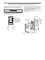
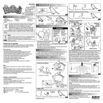
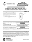
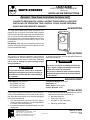
1A65/1A65W
ELECTRIC-HEAT THERMOSTAT
WHITE-RODGERS
(Single Pole)
INSTALLATION INSTRUCTIONS
Operator: Save these instructions for future use!
FAILURE TO READ AND FOLLOW ALL INSTRUCTIONS CAREFULLY BEFORE
INSTALLING OR OPERATING THIS CONTROL COULD CAUSE PERSONAL
INJURY AND/OR PROPERTY DAMAGE.
DESCRIPTION
The Type 1A65/1A65W Electric Heat Thermostat is designed for use on all types of electrical heating installations such as cable heat, baseboards, wall insert heaters,
etc. Its narrow operating differential and the ability of its
fully exposed knob to sense both radiant heat and room
air temperature make this control ideal for use on such
installations.
Dial Setting: Knob may be set anywhere between 40°
and 85°F by simply turning knob so that indicator on knob
points to the desired setting.
60
70
50
80
PRECAUTIONS
This control is a precision instrument, and should be
handled carefully. Rough handling or distorting components could cause the control to malfunction. Take care
not to push or damage the knob sensing element
during installation.
All wiring must conform to local and national electrical
codes and ordinances.
!
WARNING
! CAUTION
Do not use on circuits exceeding specified voltages. Higher voltages will damage control and
could cause shock or fire hazard.
To prevent electrical shock and/or equipment
damage, disconnect electric power to system, at
main fuse or circuit breaker box, until installation
is complete.
Do not use on inductive loads. Inductive (motor)
loads will damage control and could cause shock
or fire hazard.
SPECIFICATIONS
Switch Rating: Non-Inductive
22A (2500W) 120 VAC
22A (5000W) 240 VAC
18A (5000W) 277 VAC
Temperature Range: 40° to 85°F
Differential: 1°F
Switch Action: Open on rise
Contact Structure: SPST
INSTALLATION
If the heating equipment manufacturer has made provisions or recommendations for the location of this control,
then follow those instructions. If not, the following suggestions should be observed.
1. The control should be mounted in the wall, approximately five feet from the floor, as near as possible to
the centre of the controlled area.
2. It should be mounted on a partitioning wall, not on an
outside wall.
WHITE-RODGERS DIVISION
EMERSON ELECTRIC CO.
9797 REAVIS RD., ST. LOUIS, MO. 63123
(314) 577-1300, Fax (314) 577-1517
9999 HWY. 48, MARKHAM, ONT. L3P 3J3
(905) 475-4653, FAX (905) 475-4625
3. It should be mounted as far as possible from undesirable sources of heat and cold such as:
a. Windows and doors
b. Direct rays from sun
c. Hot water or cold water pipes
d. Adjoining outside walls
Printed in U.S.A.
PART NO. 37-5427C
Replaces 37-5427B
9520
WIRING
All wiring must conform to local and national electrical codes and ordinances.
The thermostat may be mounted in any standard 2” x 3”
electrical outlet box. For ease of installation use a deep
type box.
! CAUTION
USE WITH COPPER CONDUCTORS ONLY.
2. Push the lead wires into the outlet box and mount the
thermostat to the outlet box with screws provided.
Take care not to push or damage the knob sensing element during installation.
3. Snap on the thermostat cover and turn knob to
desired setting.
1. Make electrical connection to thermostat leads with
wire nuts or other local code approved devices. All
connections must be tight.
Thermostat
Mounting Screw
BLUE
BLACK
Note: Do not
push on this knob
because calibration
will be changed
if knob is bent.
60
70
50
80
LINE
LOAD
Cover
Mounting Screw