1
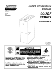
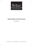
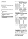
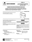
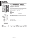
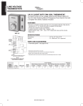
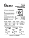
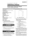
1A11-2
Fan Coil Heating-Cooling Thermostat
INSTALLATION INSTRUCTIONS
Operator: Save these instructions for future use!
FAILURE TO READ AND FOLLOW ALL INSTRUCTIONS CAREFULLY
BEFORE INSTALLING OR OPERATING THIS CONTROL COULD CAUSE
PERSONAL INJURY AND/OR PROPERTY DAMAGE.
DESCRIPTION
The 1A11-2 thermostat controls line voltage valves and/
or blower motors on fan coil units in manual changeover,
heating/cooling systems. It features a system switch for
manual selection of heat -off-cool, a three speed manual
fan control switch, an adjustable temperature dial with
a 36 to 90°F range, and an indicating thermometer, all
combined in one deluxe-styled control.
50
60
70
80
FAN
90
HIGH
MED
LOW
WHITE-RODG
ERS
60
70
50
80
Color-coded leads are provided for connection to field
wiring. The thermostat can be wired to perform the
following functions:
-
HEAT
OFF
40
90
COOL
SYSTEM
Thermostat cycles both fan and valve.
Thermostat cycles fan only.
Thermostat cycles valve only.
System switch “OFF” breaks all circuits.
PRECAUTIONS
If in doubt about whether your wiring is millivolt, line, or
low voltage, have it inspected by a qualified heating and
air conditioning contractor, electrician, or someone familiar with basic electricity and wiring.
Do not exceed the specification ratings.
! CAUTION
To prevent electrical shock and/or equipment
damage, disconnect electric power to system, at
main fuse or circuit breaker box, until installation is complete.
All wiring must conform to local and national electrical
codes and ordinances.
This control is a precision instrument, and should be
handled carefully. Rough handling or distorting components could cause the control to malfunction.
!
WARNING
Do not use on circuits exceeding specified voltage. Higher voltage will damage control - could
cause shock or fire hazard.
White-Rodgers is a division
of Emerson Electric Co.
www.white-rodgers.com
PART NO. 37-4113E
Replaces 37-4113D
0547
SPECIFICATIONS
Switch Action: SPDT
(Heating - open on rise)
(Cooling - close on rise)
Temperature Range: 36°F to 90°F (2°C to 32°C)
! CAUTION
When the thermostat is set below 40°F (5°C),
damage to the building and/or contents may
result due to freezing. This is possible due to
factory calibration tolerances, thermostat location and operating characteristics of the heating equipment.
Contact Structure: Snap action
Electrical Rating:
VOLTAGE (AC)
Full Load Amps.
120V
5.5
Locked Rotor Amps.
33.0
Pilot Duty
240V
2.75
277V
2.3
16.5
13.8
125VA
Mounting: Standard 2 x 4 inch outlet box or 2-ganged
outlet boxes. Mounting screws are provided with the
thermostat. With a standard adapter plate (not provided), this thermostat may be mounted on a 4 inch
square junction box
System Switch: Heat - Off - Cool
Fan Switch : Low - Medium - High
INSTALLATION
SELECT THERMOSTAT LOCATION
Proper location insures that the thermostat will provide
a comfortable home temperature. Observe the following general rules when selecting a location:
1. Locate thermostat about 5 ft. above the floor.
2. Install thermostat on a partitioning wall, not on an
outside wall.
3. Never expose thermostat to direct light from lamps,
sun, fireplaces or any temperature radiating equipment.
4. Avoid locations close to windows, adjoining outside
walls, or doors that lead outside.
5. Avoid locations close to air registers or in the direct
path of air from them.
6. Make sure there are no pipes or duct work in that
part of the wall chosen for the thermostat location.
7. Never locate thermostat in a room that is warmer or
cooler than the rest of the home, such as the kitchen.
8. Avoid locations with poor air circulation, such as
behind doors or in alcoves.
9. The living or dining room is normally a good location,
provided there is no cooking range or refrigerator on
opposite side of wall.
INSTALL THERMOSTAT
Install the thermostat as follows:
1. Before mounting, connect system wiring to proper
color-coded leads at rear of thermostat. Follow
equipment manufacturer's instructions or refer to
wiring diagram for typical system hookups.
2. Remove thermostat cover by grasping top and bottom
of cover and pull straight out. Dress wiring into junction
box and secure thermostat to outlet box with mounting
screws.
NOTE
DO NOT PUSH OR DAMAGE THE TEMPERATURE
KNOB DURING INSTALLATION.
3. Install thermostat cover, turn knob to desired setting, and set selector switches for the appropriate
system function and fan speed.
ADAPTER PLATE
(NOT PROVIDED)
4x4
JUNCTION
BOX
! CAUTION
FAN
To prevent electrical shock and/or equipment
damage, disconnect electric power to system
at main fuse or circuit breaker box until installation is complete.
The thermostat may be mounted on a standard 2 x 4
inch vertical outlet box or 2-ganged outlet boxes. When
mounting to a 4 x 4 inch junction box is required, use of
a standard adapter plate (not provided) is necessary.
USE COPPER CONDUCTORS ONLY.
2
LOW
HEAT
SYST
EM
50
USE 2 x 4 OR 4 x 4
JUNCTION BOX
WH
80
60 70
90
S
ER
DG
-RO
ITE
70
60
80
1A11-2
50
MOUNTING
SCREWS (2)
90
40
40
INSTALLATION (cont’d)
WIRING
NOTE
! CAUTION
This typical wiring diagram shows only the terminal
identification and wiring hookup. Always refer to wiring
instructions, provided by equipment manufacturer, for
system hookup operation.
All wiring should be done according to local and national
electrical codes and ordinances.
- For the thermostat to cycle fan only (if valve is
not used), do not connect the thermostat orange
wire to the system. Wrap orange lead with approved
electrical tape or wire nut to prevent shorting.
- For the thermostat to cycle the valve only (with
fan on continuously), Connect orange wire to L1
and black wire to VALVE. Connect all other wires as
shown.
NOTE: With the system switch in the OFF position, the
thermostat will prevent both the fan and valve circuits
from turning on.
GREEN
VALVE L1*
(SOL) (HOT) GND
BLACK
CUSTOMER
CONNECTIONS
LOW
RED
- For the thermostat to cycle both fan and valve,
connect all wires as shown.
TAN
Varying the wiring can alter the thermostat/system
operation as shown below:
MED
BLUE
FAN
HIGH
ORANGE
To prevent electrical shock and/or equipment
damage, disconnect electric power to system
at main fuse or circuit breaker box until installation is complete.
THERMOSTAT
SCHEMATIC
HIGH
MED
FAN
SWITCH
LOW
RED
COOL
HEAT
SYSTEM
SWITCH
HEAT
OFF
COOL
BLUE
*L1 is Power In
Note: Above FAN and SYSTEM switches shown in
MED and HEAT positions respectively.
1A11-2
5-wire with ground, for single valve,
manual heat/cool changeover
The Emerson logo is a
trademark and a service mark
of Emerson Electric Co.
3