Transcript
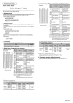
Signal layout of external device connector
BCN-B62008-269-B(1406)MEE
QD75M1
QD75M2
External device connector
(module side)
QD75M4
Pin
number
Pin
number
Signal name
(Note-3)
(Note-1)
Before Using the Product
Axis4
(AX4)
Please read this document before use. Keep the document in a safe place for future reference.
Make sure that the end users read the document.
Related manuals
Before using the product, please read "Safety Guidelines" that is supplied with the base unit.
Read the Servo Amplifier Instruction Manual of servo amplifier that uses it.
Confirm the following descriptions:
SAFETY PRECAUTIONS
CONDITIONS OF USE FOR THE PRODUCT
EMC AND LOW VOLTAGE DIRECTIVES
WARRANTY
Manuels associés
Avant d'utiliser ce produit, prenez la peine de lire les "Consignes de sécurité" fournies avec
l'unité de base.
Lire le Manuel d'Instructions du Servo-Amplificateur correspondant au servo-amplificateur
utilisé.
2B20
2B19
2B18
2B17
2B16
2B15
2B14
2B13
2B12
2B11
2B10
2B9
2B8
2B7
2B6
2B5
2B4
2B3
2B2
2B1
(Note-1)
Axis3
(AX3)
2A20
2A19
2A18
2A17
2A16
2A15
2A14
2A13
2A12
2A11
2A10
2A9
2A8
2A7
2A6
2A5
2A4
2A3
2A2
2A1
(Note-2)
Axis2
(AX2)
Axis1
(AX1)
1B20
1B19
1B18
1B17
1B16
1B15
1B14
1B13
1B12
1B11
1B10
1B9
1B8
1B7
1B6
1B5
1B4
1B3
1B2
1B1
1A20
1A19
1A18
1A17
1A16
1A15
1A14
1A13
1A12
1A11
1A10
1A9
1A8
1A7
1A6
1A5
1A4
1A3
1A2
1A1
Front view of the module
1B19
1B18
1B17
1B16
1B15
1B14
1B13
1B12
1B11
1B10
1B9
1B8
1B7
1B6
1B5
1B4
1B3
1B2
1B1
Manual pulse generator B
common (PULSER B-)
Manual pulse generator A
common (PULSER A-)
1A20
1A19
1A18
1A17
1A16
1A15
1A14
1A13
1A12
1A11
1A10
1A9
1A8
1A7
1A6
No connect
Common (COM)
External command signal/
switching signal (CHG)
Stop signal (STOP)
Near-point dog signal (DOG)
Lower limit signal (RLS)
Upper limit signal (FLS)
1A5
1A4
1A3
1A2
1A1
Manual pulse generator B
phase/SIGN (PULSER B+)
Manual pulse generator A
phase/PLS (PULSER A+)
No connect
Common (COM)
External command signal/
switching signal (CHG)
Stop signal (STOP)
Near-point dog signal (DOG)
Lower limit signal (RLS)
Upper limit signal (FLS)
(Note-1): These axes are not available for the QD75M1 and QD75M2.
(Note-2): For the QD75M1, 1B1 to 1B18 terminals are "No connect".
(Note-3): 1A(B)20 to 1A(B)1 indicates in the case of axis 1 and axis 2 terminals of
the connector.
For the 2A(B)20 to 2A(B)1 terminals of axis 3 and axis 4, refer to
1A(B)20 to 1A(B)1. The 2A(B)20 to 2A(B)8 terminals are "No connect".
Revoir les points suivants :
PRÉCAUTIONS DE SÉCURITÉ
CONDITIONS D'UTILISATION DU PRODUIT
DIRECTIVES EMC ET BASSE TENSION
GARANTIE
1B20
Signal name
(Note-3)
The table below shows applicable external device connectors.
When wiring, use applicable wires.
Details of the product are also described in the manual shown below (sold separately).
Please read the manual and understand the functions and performance of the product to
use it correctly.
• Type QD75M Positioning Module User's Manual (Details)
IB-0300062 (1XB752)
Packing list
External device connector
Tightening
Model
torque
A6CON1
A6CON2
External
0.20 to
device
0.29N•m
A6CON3
connector
Wire
A6CON4
Diameter
Type
Material
Temperature
rating
22 AWG
24 AWG
28 AWG
30 AWG
22 AWG
Stranded
Stranded
Stranded
Solid
Stranded
Copper
75°C (167°F)
or more
Check that the following items are included in the package.
Item
Module
"Before Using the Product" (this document)
Quantity
1
1
Affectation des signaux au connecteur du dispositif externe
Connecteur du dispositif externe Numéro
de
(côté module)
broche
(Note-1)
(Note-1)
(Note-2)
Numéro
de
broche
Nom du signal
(Note-3)
Axe 4
(AX4)
Axe3 Axe2
(AX3) (AX2)
Axe1
(AX1)
2B20
2B19
2B18
2B17
2B16
2B15
2B14
2B13
2B12
2B11
2B10
2B9
2B8
2B7
2B6
2B5
2B4
2B3
2B2
2B1
2A20
2A19
2A18
2A17
2A16
2A15
2A14
2A13
2A12
2A11
2A10
2A9
2A8
2A7
2A6
2A5
2A4
2A3
2A2
2A1
1B20
1B19
1B18
1B17
1B16
1B15
1B14
1B13
1B12
1B11
1B10
1B9
1B8
1B7
1B6
1B5
1B4
1B3
1B2
1B1
1A20
1A19
1A18
1A17
1A16
1A15
1A14
1A13
1A12
1A11
1A10
1A9
1A8
1A7
1A6
1A5
1A4
1A3
1A2
1A1
1B20
1B19
1B18
1B17
1B16
1B15
1B14
1B13
1B12
1B11
1B10
1B9
1B8
1B7
1B6
1B5
Vue de l'avant du module
1B4
1B3
1B2
1B1
Nom du signal
(Note-3)
Générateur d'impulsions
manuel B Commun (PULSER
B-)
Générateur d'impulsions
manuel A Commun (PULSER
A-)
1A20
1A19
1A18
1A17
1A16
1A15
1A14
1A13
1A12
1A11
1A10
1A9
1A8
1A7
1A6
Non connecté
Commun (COM)
Signal de commande externe/
signal de commutation (CHG)
Signal d'arrêt (STOP)
Signal de surveillance point
d'approche (DOG)
Signal de limite inférieure
(RLS)
Signal de limite supérieure
(FLS)
1A5
1A4
1A3
1A2
1A1
Générateur d'impulsions
manuel Phase B/SIGN
(PULSER B+)
Générateur d'impulsions
manuel Phase A/PLS
(PULSER A+)
Non connecté
Commun (COM)
Signal de commande externe/
signal de commutation (CHG)
Signal d'arrêt (STOP)
Signal de surveillance point
d'approche (DOG)
Signal de limite inférieure
(RLS)
Signal de limite supérieure
(FLS)
(Note-1): Ces axes ne sont pas disponibles sur les QD75M1 et QD75M2.
(Note-2): Sur le QD75M1, 1B1 à 1B18 sont "Non connecté".
(Note-3): 1A(B)20 à 1A(B)1 correspondent aux bornes d'axe 1 et d'axe 2 du
connecteur.
Pour les bornes 2A(B)20 à 2A(B)1 des axes 3 et 4, voir 1A(B)20 à
1A(B)1. Les bornes 2A(B)20 à 2A(B)8 sont "Non connecté".
Le tableau ci-dessous indique quels connecteurs on peut utiliser pour le dispositif externe.
Pour le câblage, utiliser les fils prescrits.
Connecteur du dispositif externe
Couple de
Modèle
serrage
A6CON1
A6CON2
Connecteur
0,20 à
du dispositif
0,29N•m
A6CON3
externe
A6CON4
Fil
Diamètre
Type
Matériau
Classe de
température
22 AWG
24 AWG
28 AWG
30 AWG
22 AWG
Torsadé
Torsadé
Torsadé
Monobrin
Torsadé
Cuivre
75°C (167°F)
ou plus
Operating ambient temperature
Use the product within the range from 0°C to 55°C (32°F to 131°F).
Température ambiante de fonctionnement
Utiliser le produit à une température ambiante entre 0°C et 55°C (32°F et 131°F).
QD75M-U-HW