1
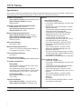
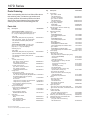
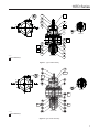
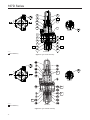
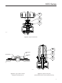
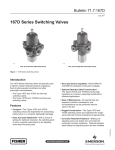
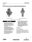
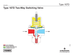
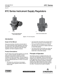
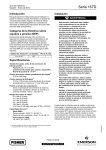
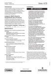
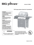
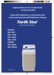
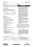
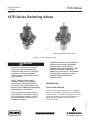
167D Series
Instruction Manual
Form 5859
June 2011
167D Series Switching Valves
P1185
P1184
TYPE 167D TWO-WAY SWITCHING VALVE
TYPE 167DA THREE-WAY SWITCHING VALVE
Figure 1. 167D Series Switching Valves
!
WARNING
Failure to follow these instructions or
to properly install and maintain this
equipment could result in an explosion,
fire and/or chemical contamination
causing property damage and personal
injury or death.
Fisher® switching valves must be
installed, operated, and maintained
in accordance with federal, state, and
local codes, rules, and regulations, and
Emerson Process Management Regulator
Technologies, Inc. instructions.
Introduction
Scope of the Manual
This manual provides instructions for the installation,
maintenance, and parts ordering for the 167D Series
Switching Valves. Instructions and parts lists for other
equipment mentioned in this instruction manual, as
well as for other switching valves are found in
separate manuals.
D103234X012
If the switching valve vents gas or a
leak develops in the system, service
to the unit may be required. Failure
to correct trouble could result in a
hazardous condition.
Installation, operation, and maintenance
procedures performed by unqualified
personnel may result in improper
adjustment and unsafe operation. Either
condition may result in equipment
damage or personal injury. Use qualified
personnel when installing, operating,
and maintaining the 167D Series
switching valves.
www.fisherregulators.com
167D Series
Specifications
Some general 167D Series switching valve ratings and other specifications are given on this page. A label on the
spring case gives the control spring range for a given valve as it comes from the factory.
Available Configurations
Types 167D and 167DS: Two-way switching valve
Types 167DA and 167DAS: Three-way
switching valves
Body Size, Inlet and Outlet Connection Style
Ports A and C: 1/4 or 1/2 NPT
Vent and Control Pressure Connections
(Port D) and Port B: 1/4 NPT
Maximum Operating Inlet Pressure(1)
Types 167D and 167DS: 400 psig / 27,6 bar
Types 167DA and 167DAS: 125 psig / 8,6 bar
Types 167DA and 167DAS (NACE):
100 psig / 6,9 bar
Set Pressure Ranges
See Tables 1 and 2
Maximum Diaphragm Pressure(1)
150 psi / 10,3 bar over outlet pressure setting up
to a maximum of 250 psi / 17,2 bar
Flow and Sizing Coefficients
See Table 3
Spring Case Vent Location
Aligned with inlet (standard), other positions optional
Temperature Capabilities(1)
Nitrile (NBR)
Standard Service (Types 167D and 167DA only):
-20° to 180°F / -29° to 82°C
Low Temperature Service (Types 167D and 167DA only) and Standard Service (Types 167DS
and 167DAS only): -40° to 180°F / -40° to 82°C
Fluorocarbon (FKM)
High Temperature Service: 0° to 300°F /
-18° to 149°C
Approximate Weights
Types 167D and 167DA: 1.2 pounds / 0,5 kg
Types 167DS and 167DAS: 2.8 pounds / 1 kg
Options
Types 167D and 167DA
• Handwheel adjusting screw
• Fluorocarbon (FKM) diaphragm, soft seat, seat,
and O-rings
• Stainless steel valve stem and plug. Includes
stainless steel seat
• 1-hole panel mount with handwheel adjusting
screw and 1/4 NPT tap spring case
• 3-hole panel mount bonnet with handwheel
adjusting screw and 1/4 NPT spring case
• 1/4 NPT tapped vent spring case
• 1/4 NPT tapped vent and closing cap
• Adjusting screw with locknut and a lock wire to
one flange bolt (For Type 167D only)
• Panel mounting bracket. Includes 1/4 NPT
spring case, standard adjusting screw, nut,
and bracket
• Yoke mounting bracket. Includes 1/4 NPT
spring case, standard adjusting screw, nut,
fasteners, and bracket
• Size 30-70 casing mounting bracket. Includes
1/4 NPT spring case, standard adjusting screw,
nut, fasteners, and bracket
• NACE MR0175 or NACE MR0103 construction(2)
Types 167DS and 167DAS
• Handwheel adjusting screw
• Fluorocarbon (FKM) diaphragm, soft seat, seat,
and O-rings
• 1-hole panel mount with handwheel adjusting
screw and 1/4 NPT tap spring case
• Panel mounting bracket. Includes 1/4 NPT
spring case, standard adjusting screw, nut, and
bracket
• Yoke mounting bracket. Includes 1/4 NPT
spring case, standard adjusting screw, nut,
fasteners,
and bracket
• Size 30-70 casing mounting bracket. Includes
nut, fasteners, and bracket
1. The pressure/temperature limits in this Instruction Manual and any applicable standard or code limitation should not be exceeded.
2. Product complies with the material requirements of NACE MR0175 or MR0103. Environmental limits may apply.
2
167D Series
ADJUSTING SCREW
ADJUSTING SCREW
CONTROL SPRING
SOFT SEAT
CONTROL SPRING
DIAPHRAGM
O-RING
DIAPHRAGM
O-RING
PORT C
PORT A
VALVE STEM
BODY
PORT C
PORT A
VALVE PLUG
ORIFICE SEAT
VALVE STEM
VALVE SPRING
ORIFICE SEAT
M1151
VALVE PLUG
BODY
M1152
VALVE SPRING
PORT B
URE
TYPE
167DA
THREE-WAY
SURE (WHEN LOADING PRESSURE IS LESS THAN SETPOINT) SWITCHING VALVE
SURE (WHEN LOADING PRESSURE IS EQUAL TO OR GREATER THAN SETPOINT)
C PRESSURE
INLET
PRESSURE
INLET
PRESSURE
SSURE
TYPE 167D TWO-WAY SWITCHING VALVE
OUTLET
PRESSURE
(WHEN LOADING
PRESSURE ISPRESSURE
LESS THAN SETPOINT)
OUTLET
PRESSURE
(WHEN LOADING
IS LESS THAN SETPOINT)
OUTLET
PRESSURE
(WHEN LOADING
PRESSURE ISPRESSURE
EQUAL TO OR IS
GREATER
THAN
OUTLET
PRESSURE
(WHEN LOADING
EQUAL
TOSETPOINT)
OR GREATER
ATMOSPHERIC
PRESSURE
ATMOSPHERIC
PRESSURE
LOADING
PRESSURE
LOADING
PRESSURE
THAN SETPOINT)
Figure 2. 167D Series Operational Schematics (Port D not shown)
Table 1. Three-Way Switching Valves Set Pressure Ranges and Control Spring Data
SET PRESSURE RANGE
TYPE
167DA
167DAS
Port A or C
as Inlet
CONTROL SPRING DATA
Port B as Inlet
Color Code
Material
Part Number
Wire Diameter
psig
bar
psig
bar
Inch
mm
14 to 20
16 to 35
0,97 to 1,4
1,1 to 2,4
7 to 20
10 to 30
0,48 to 1,4
0,69 to 2,1
White stripe
Purple stripe
Zinc-plated
Music Wire
GE40282X012
GE40283X012
0.145
0.156
3,68
3,96
25 to 60
40 to 125
1,7 to 4,1
2,8 to 8,6
25 to 50
40 to 90
1,7 to 3,4
2,8 to 6,2
Brown stripe
Pink stripe
Chrome
Silicon
14 to 20
16 to 35
25 to 60
40 to 125
0,97 to 1,4
1,1 to 2,4
1,7 to 4,1
2,8 to 8,6
7 to 20
10 to 30
25 to 50
40 to 90
0,48 to 1,4
0,69 to 2,1
1,7 to 3,4
2,8 to 6,2
White
Purple
Brown
Pink
Inconel®
X-750
GE40284X012
GE40345X012
GE40320X012
GE40321X012
GE40322X012
GE40323X012
0.172
0.207
0.148
0.162
0.177
0.218
4,37
5,26
3,76
4,12
4,50
5,54
MAXIMUM
PRESSURE
CHANGE ON
TO SHIFT FROM
Free Length PORT B CLOSED
TO PORT C
CLOSED
Inch
mm
1.425
36,2
1.750
44,4
psid
bar d
10
13
0,69
0,90
17
35
8
12
16
31
1,2
2,4
0,55
0,83
1,1
2,1
Table 2. Two-Way Switching Valves Set Pressure Ranges and Control Spring Data
SET PRESSURE RANGE
TYPE
167D
167DS
Port A as Inlet
psig
bar
3 to 15
5 to 20
5 to 35
25 to 60
40 to 125
5 to 20
5 to 35
25 to 60
40 to 125
50 to 150
0,21 to 1,0
0,34 to 1,4
0,34 to 2,4
1,7 to 4,1
2,8 to 8,6
0,34 to 1,4
0,34 to 2,4
1,7 to 4,1
2,8 to 8,6
3,4 to 10,3
CONTROL SPRING DATA
Color Code
Yellow stripe White stripe
Purple stripe
Brown stripe
Pink stripe
White
Purple
Brown
Pink
Gold
Material
Zinc-plated
Music Wire
Chrome Silicon
Inconel® X-750
Part Number
GG00421X012
GE40282X012
GE40283X012
GE40284X012
GE40345X012
GE40320X012
GE40321X012
GE40322X012
GE40323X012
GE40324X012
Wire Diameter
Inch
mm
0.142
0.145
0.156
0.172
0.207
0.148
0.162
0.177
0.218
0.234
3,61
3,68
3,96
4,37
5,26
3,76
4,12
4,50
5,54
5,94
Free Length
Inch
mm
1.425
36,2
1.750
44,4
Inconel® is a mark owned by Special Metals Corporation.
3
167D Series
Product Description
valve or associated equipment may cause leakage,
parts damage, or personal injury due to bursting of
pressure-containing parts or explosion of accumulated
gas. Switching valve operation within ratings does
not preclude the possibility of damage from external
sources or from debris in the pipeline. A switching
valve should be inspected for damage periodically and
after any overpressure condition.
The 167D Series switching valves are pneumatically
operated and controlled units, built with a wide range of
capabilities to handle those switching applications that
involve venting, on-off control, and failure modes.
• The Types 167D and 167DS are two-way switching valves.
• The Types 167DA and 167DAS are three-way switching valves.
Installation
Note
If the switching valve is shipped
mounted on another unit, install that
unit according to the appropriate
Instruction Manual.
Principle of Operation
Refer to Figure 2 and also refer to Figures 3 through
5 for port D location. Control pressure enters the
switching valve through port D (not shown in Figure 2)
and registers under the diaphragm. Control pressure
overcomes the spring force and the diaphragm and
raise the valve plug, closing port C and opening port B
of the Type 167DA three-way switching valve. In this
condition, the Type 167D construction is turned off and
the Type 167DA construction provides flow from path
A to B. If, either intentionally or through pneumatic
failure, the control pressure drops below the spring
force, the diaphragm and valve plug move downward,
opening port C and closing port B of the Type 167DA
three-way switching valve. In this condition both
constructions provide a flow path from port A to
port C. The pressure change necessary to switch the
valve depends on the spring used and the setting of
the adjusting screw on the switching valve.
!
WARNING
Personal injury, property damage,
equipment damage, or leakage due to
escaping gas or bursting of pressurecontaining parts may result if this
switching valve is overpressured or
is installed where service conditions
could exceed the limits given in the
Specifications section, or where
conditions exceed any ratings of the
adjacent piping or piping connections.
To avoid such injury or damage,
provide pressure-relieving or pressurelimiting devices (as required by the
appropriate code, regulation, or
standard) to prevent service conditions
from exceeding those limits.
Overpressure Protection
Before installing a Type 167D, 167DA, 167DS, or
167DAS switching valve, be sure the installation
complies with the following installation guidelines:
The 167D Series switching valves have maximum
outlet pressure ratings that are lower than their
maximum inlet pressure ratings. A pressurerelieving or pressure-limiting device is needed if inlet
pressure can exceed the maximum outlet pressure
rating. Overpressuring any portion of a switching
1. Switching valve operation within ratings does not preclude the possibility of damage from debris in Table 3. Flow and Sizing Coefficients
TYPES
167D, 167DS
BODY SIZE
1/4 NPT
1/2 NPT
All sizes
167DA, 167DAS
1/4 NPT
1/2 NPT
4
PORT
C
B
C
WIDE-OPEN FLOW COEFFICIENTS
C1
IEC SIZING
COEFFICIENTS
Cg
Cv
41.46
1.09
37.56
0.89
Xt
46.50
1.18
39.03
0.96
27.79
0.96
28.74
0.52
49.35
1.60
30.58
0.59
58.86
1.81
32.22
0.66
167D Series
TYPE 167DA OR 167DAS
D
A
TYPE
DVC6010
C
B
A
TYPE 657
B
1/4 NPT SUPPLY
10C0622
TYPE 67CFR
Figure 3. Typical 167DA or 167DAS Installation
(Lockup system using Type 167DA or 167DAS to close air circuit to diaphragm of main valve in case of plant air failure. Main valve
will remain in position it occupied at time of supply pressure failure.)
TYPE 167D OR 167DS SWITCHING
VALVE SET TO OPEN AT
5 PSI / 0,34 bar
PRESSURE GAUGE
D
A
COOLING TOWER
PUMP
WHISTLE
C
TO INSTRUMENT AIR SUPPLY
55 PSI / 3,8 bar
PUMP DISCHARGE
AF8400
Figure 4. Typical 167D or 167DS Installation
(Warning system using Type 167D or 167DS two-way valve to activate a whistle when pump discharge pressure falls.)
TYPE 167DA
OR 167DAS
D
A
B
TYPE 657
S
2
1
C
ASCO SOLENOID
DE-ENERGIZED
3
VENT
SUPPLY
TYPE
DVC6010/
67CFR
FACTORY (1/4 O.D.) OR
CUSTOMER SUPPLIED TUBING
(PIPED BY CUSTOMER)
CHECK
VALVE
1/4 NPT
GE37992
3/4 NPT
VOLUME TANK
SHIPPED WITH ACTUATOR
Figure 5. Typical Switching Valve Schematic
5
167D Series
the lines or from external sources. Switching valves should be inspected for damage periodically and after any overpressure condition.
2. Only personnel qualified through training and experience should install, operate, and maintain
a switching valve. Make sure that there is no damage to or foreign material in the switching valve. Also ensure that all tubing and piping is
free of debris.
3. Install the switching valve to achieve the desired switching results. Connect the control pressure line to either D port. Verify that the other D port is plugged. The port labeled “IN” or port A is the
common inlet connection and ports B and C are
the outlet connections. Flow is either from A to B
or A to C.
4. A clogged spring case vent hole may cause the switching valve to function improperly. To keep this vent hole from being plugged (and to keep the spring case from collecting moisture, corrosive chemicals, or other foreign material) orient the vent to the lowest possible point on the spring case or otherwise protect it.
Inspect the vent hole regularly to make sure it is not plugged. Spring case vent hole orientation may be changed by rotating the spring case with respect to the body. A 1/4 NPT spring case vent may be remotely vented by installing obstruction-free tubing or piping into the vent. Protect the remote vent by installing a screened vent cap on the remote end of the
vent pipe. 5. For use in switching valve shutdown, install upstream block and vent valves and downstream
block and vent valves (if required), or provide
some other suitable means of properly venting the
switching valves inlet and outlet pressures. Install
a pressure gauge to monitor instruments
on startup.
6. Apply a good grade of pipe compound to the
external pipe threads before making connections,
making sure not to get the pipe compound inside
the switching valves.
7. Install tubing fitting or piping into the threaded NPT
inlet connection on the body (key 1) and into the
threaded NPT outlet connections.
8. The 1/4 NPT control pressure ports must be
plugged if not in use.
6
Startup and Adjustment
Key numbers are referenced in Figures 7 through 13.
1. With proper installation completed and downstream equipment properly adjusted, slowly open the
upstream and downstream shut-off valve (when
used) while using pressure gauges to
monitor pressure.
!
WARNING
To avoid personal injury, property
damage, or equipment damage caused
by bursting of pressure containing parts
or explosion of accumulated gas, never
adjust the control spring to produce an
outlet pressure higher than the upper
limit of the outlet pressure range for that
particular spring. If the desired outlet
pressure is not within the range of the
control spring, install a spring of the
proper range according to the diaphragm
parts maintenance procedure.
2. If outlet pressure adjustment is necessary,
monitor outlet pressure with a gauge during the
adjustment procedure. The switching valve
is adjusted by loosening the hexnut (key 19),
if used, and turning the adjusting screw or
handwheel (key 18) clockwise to increase or counterclockwise to decrease the outlet pressure setting. Retighten the hexnut to maintain the
adjustment position.
Maintenance
Switching valve parts are subject to normal wear and
must be inspected and replaced as necessary. The
frequency of inspection and replacement of parts
depend on the severity of service conditions and
applicable codes and government regulations.
Note
If sufficient clearance exists, the body
(key 1) may remain mounted on other
equipment or in a line or panel during
maintenance unless the entire switching
valve will be replaced.
167D Series
WARNING
POSITION 2
To avoid personal injury, property damage,
or equipment damage caused by sudden
release of pressure or explosion of
accumulated gas, do not attempt any
maintenance or disassembly without first
isolating the switching valve from system
pressure and relieving all internal pressure
from the switching valve.
POSITION 3
POSITION 4
!
Trim Maintenance
Key numbers are referenced in Figures 7 through 10.
1. Unscrew the spring retainer (key 48) and separate
the spring retainer and O-ring (key 14) from the
body (key 1).
2. Inspect the removed parts for damage and debris.
Replace any damaged parts. Apply a high
quality lubricant to the O-ring (key 50)
before reassembling.
3. To remove the valve stem (key 11) and valve plug
(key 57), grasp the end and pull it straight
out of the body (key 1). Inspect the parts for
damage and debris. Replace any damaged parts.
The valve stem and valve plug may be cleaned or
replaced. Types 167D and 167DS: If the soft seat
(key 15) was removed, make sure it is properly
snapped into place before installing the valve
stem. Apply a high quality lubricant to the O-ring
(key 50) before reinstalling the valve stem.
4. Install valve stem and valve plug by sliding the
valve stem through center of the seat (key 58)
until the valve plug contacts the seat. Apply
lubricant to O-ring (key 14) and thread in spring
retainer (key 48). Torque spring retainer to
18 to 22 foot-pounds / 24 to 30 N•m.
Diaphragm Maintenance
Key numbers are referenced in Figures 7, 8, 9, 10,
and 12.
1. Back out the adjusting screw or handwheel (key 18)
until compression is removed from the spring (key 17).
2. Remove the flange screws (key 3) to separate
the spring case assembly (key 7) from the body
(key 1). Remove the upper spring seat (key 20)
and the control spring (key 17).
3. Remove the diaphragm assembly (key 16),
inspect the diaphragm, and replace the assembly,
if necessary.
GE31784
POSITION 1 (ALIGNED WITH INLET) (STANDARD)
Figure 6. 167D Series Spring Case Vent Positions
4. Place the diaphragm assembly (key 16) on the body
(key 1) as shown in Figures 7 through 10. Push down
on the diaphragm assembly to make sure the valve
plug (key 57) strokes smoothly and approximately
1/16-inch / 1,6 mm.
Note
In step 5, if installing a control spring of
a different range, be sure to delete the
spring range originally appearing on the
label and indicate the new spring range.
5. Stack the control spring (key 17) and upper spring
seat (key 20) onto the diaphragm assembly (key 16).
6. Install the spring case assembly (key 7) on the body
(key 1) with the vent oriented to prevent clogging or
entrance of moisture. Install the six flange
screws (key 3) using a crisscross pattern and torque
to 15 to 30-inch-pounds / 1,7 to 3,4 N•m.
Note
On Types 167DS and 167DAS, lubricate
the adjusting screw (key 18) thread to
reduce galling of the stainless steel.
7. When all maintenance is complete, refer to
the Startup and Adjustment section to put the
switching valve back into operation and adjust
the pressure setting. Tighten the hexnut (key 19)
if used, and install the closing cap (key 33) if used.
7
167D Series
Parts Ordering
Key When corresponding with the local Sales Office about
this switching valve, include the type number and
all other pertinent information printed on the label.
Specify the eleven-character part number when
ordering new parts from the following parts list.
Parts List
Key Description Types 167D and 167DS - Includes O-ring
(key 14), seat (key 58), plug assembly (keys 15, 50, 57, 11, 64), and diaphragm assembly (key 16).
Type 167D
Brass/Nitrile (NBR) seat and plug assembly
Types 167D NACE, 167DS, and 167DS NACE
316L Stainless steel/Nitrile (NBR) seat and
plug assembly Part Number
R167DX00012
R167DSX0N12
Types 167DA and 167DAS - Includes O-ring (key 14), two seats (key 58), plug assembly
(keys 50, 57, 11, 64), and diaphragm
assembly (key 16).
Type 167DA
Brass/Nitrile (NBR) seat and plug assembly R167DAX0022
Types 167DA NACE, 167DAS, and 167DAS NACE
316L Stainless steel/Nitrile (NBR) seat and
plug assembly R167DASXN22
1
Body
1/4 NPT (Ports A and C)
Type 167D or 167DA, Aluminum
GE35383X012
Type 167DS or 167DAS,
CF3M/CF8M Stainless steel
GE35385X012
1/2 NPT (Ports A and C)
Type 167D or 167DA, Aluminum
GE31787X012
Type 167DS or 167DAS,
CF3M/CF8M Stainless steel
GE31804X012
3
Flange Screw
Types 167D and 167DA
   For Standard spring case and spring case
with 1/4 NPT vent (6 required), Zinc-plated steel T13526T0012
For Standard Spring Case (6 required),
316/316L Stainless steel
T13526T0042
For wire seal
Flange Screw (5 required), Zinc-plated steel T13526T0012
Flange Screw (1 required), Steel
14B3987X012
Types 167DS and 167DAS (6 required),
316L Stainless steel
T13526T0042
7
Spring Case Assembly
Types 167D and 167DA, Aluminum
Drilled hole vent (standard)T14070T0012
1/4 NPT vent
T14070T0022
Types 167DS and 167DAS,
CF8M/CF3M Stainless steel
20C1727X012
11
Valve Stem
Types 167D and 167DA,
Brass
GE35519X012
316L Stainless Steel
GE35519X032
Types 167DS and 167DAS
316L Stainless steel
GE35519X032
*Recommended Spare Parts
Inconel® is a mark owned by Special Metals Corporation.
8
Description Part Number
12* Valve Spring
Type 167D or 167DS
302 Stainless steel
GE31783X012
Inconel® X-750 (NACE)
GG00430X012
Type 167DA or 167DAS
302 Stainless steel
ERAA00153A0
Inconel® X-750 (NACE)
ERAA00154A0
14* O-ring (Spring Retainer)
Nitrile (NBR)
10A3803X092
Fluorocarbon (FKM)
10A3803X112
15
Soft Seat (Types 167D and 167DS only)
Nitrile (NBR)
T14055T0012
Fluorocarbon (FKM)
T14055T0022
16* Diaphragm Assembly
Type 167D
Nitrile(NBR)/Polyester
T14119T0022
Fluorocarbon(FKM)/Polyester
T14119T0042
Type 167DS
Nitrile(NBR)/Polyester
T14119T0062
Fluorocarbon(FKM)/Polyester
T14119T0072
Type 167DA
Nitrile(NBR)/Brass
T14119T0112
Nitrile(NBR)/316L Stainless Steel
T14119T0122
Fluorocarbon(FKM)/316L Stainless Steel
T14119T0132
Type 167DAS
Nitrile(NBR)/316L Stainless Steel
T14119T0122
Fluorocarbon(FKM)/316L Stainless Steel
T14119T0132
17
Control Spring See Tables 1 and 2 18
Adjusting Screw
Types 167D and 167DA
Zinc-plated steel (For standard spring case)
Square head (standard)T14061T0012
Handwheel
T14102T0012
Wire seal (not shown)
T14104T0012
Zinc-plated steel (For spring case with
1/4 NPT vent)
Square head for closing cap
T14101T0012
Handwheel
T14103T0012
Wire seal (not shown)
T14198T0012
316 Stainless Steel
(For Spring case with 1/4 NPT vent)
Square head for closing cap
T14101T0022
Types 167DS and 167DAS
Square head with or without closing cap,
316L Stainless steel
T14101T0022
Handwheel, Zinc-plated steel
T14103T0012
19
Hexnut
Types 167D and 167DA
Zinc-plated steel
1A946324122
316 Stainless steel
1A9463X0042
Types 167DS and 167DAS
316 Stainless steel
1A9463X0042 20
Upper Spring Seat
Types 167D and 167DA, Zinc-plated steel
T14051T0012
Types 167DS and 67DAS, 316 Stainless steel 10C1725X012
23 1/4 NPT Pipe Plug
Socket head, Steel
(for Types 167D and 167DA only)
1C333528992
Hex head, 316 Stainless steel
1A767535072
30
NACE Tag, 18-8 Stainless Steel (not shown)
19A6034X012
31
Panel Mounting Nut, 303 Stainless steel
10B2657X012
32
Wire Seal (not shown)
(for Types 167D and 167DA only)
304 Stainless steel
1U7581000A2
167D Series
18
L
19
B
B
20
7
17
L
16
3
DETAIL A
50
15
L
50
L
14
11
A
58
1
57
48
SECTION B-B
GE37632
L
APPLY LUBBRICANT (L)
12
Figure 7. Type 167D Assembly
L
L
B
B
DETAIL A
L
L
L
SECTION B-B
GF02289_B
APPLY LUBBRICANT (L)
Figure 8. Type 167DA Assembly
9
167D Series
B
B
18
33
19
L
20
7
17
45
3
DETAIL A
1
16
50
15
58
11
L
A
57
14
50
L
L
48
12
SECTION B-B
GE37724
APPLY LUBRICANT (L)
B
Figure 9. Type 167DS Assembly
L
B
DETAIL A
L
L
L
GE37725_B
APPLY LUBRICANT (L)
SECTION B-B
Figure 10. Type 167DAS Assembly
10
167D Series
18
19
31
GE37632
Figure 11. Optional Panel Mount
33
LOWER SPRING
SEAT
RETAINING RING
18
DIAPHRAGM
HEAD
19
PUSHER POST
(WITH RELIEF)
DIAPHRAGM
B2696
GE37632
Figure 12. Types 167D and 167DS
Diaphragm Assembly (Key 16)
Figure 13. Optional Closing Cap
[Only Available with the 1/4 NPT Spring Case Vent]
11
167D Series
Key Description Part Number
33
Closing Cap, Plastic
23B9152X012
45 Screen Vent (for Types 167DS and 167DAS only)
18-8 Stainless Steel 0L078343062
48 Spring Retainer
Type 167D
Aluminum
GG03555X012
Type 167DS
316L Stainless steel
GE31803X022
Type 167DA
Aluminum
GF02286X012
Type 167DAS
316L Stainless steel
GF02286X022
50* O-ring (Stem and Plug) (2 required)
Nitrile (NBR)
1H2926X0052
Fluorocarbon (FKM)
1H2926X0062
57 Valve Plug
Type 167D
Brass
GE37022X012
316L Stainless steel
GE37022X022
Type 167DS
316L Stainless steel
GE37022X022
Key Description Part Number
57
Valve Plug (continued)
Type 167DA
Brass
316L Stainless steel
Type 167DAS
316L Stainless steel
58* Orifice Seat
Types 167D and 167DA
303 Stainless steel/Fluorocarbon (FKM)
Brass/Nitrile (NBR)
316L Stainless steel/Nitrile (NBR) (NACE)
316L Stainless steel/
Fluorocarbon (FKM) (NACE)
Types 167DS and 167DAS
Stainless steel/Fluorocarbon (FKM)
Stainless steel/Nitrile (NBR)
Standard
(NACE)
Stainless steel/Fluorocarbon (FKM) (NACE)
64
Retaining Ring, Stainless steel
GE35229X012
GE35229X022
GE35229X022
GE31782X022
GE31782X032
GE31782X042
GE31782X052
GE31782X022
GE31782X012
GE31782X042
GE31782X052 GG00711X012
*Recommended Spare Parts
Industrial Regulators
Natural Gas Technologies
TESCOM
Emerson Process Management
Regulator Technologies, Inc.
Emerson Process Management
Regulator Technologies, Inc.
Emerson Process Management
Tescom Corporation
USA - Headquarters
McKinney, Texas 75069-1872, USA
Tel: +1 800 558 5853
Outside U.S. +1 972 548 3574
USA - Headquarters
McKinney, Texas 75069-1872, USA
Tel: +1 800 558 5853
Outside U.S. +1 972 548 3574
USA - Headquarters
Elk River, Minnesota 55330-2445, USA
Tels: +1 763 241 3238
+1 800 447 1250
Asia-Pacific
Shanghai 201206, China
Tel: +86 21 2892 9000
Asia-Pacific
Singapore 128461, Singapore
Tel: +65 6777 8211
Europe
Selmsdorf 23923, Germany
Tel: +49 38823 31 287
Europe
Bologna 40013, Italy
Tel: +39 051 419 0611
Europe
Bologna 40013, Italy
Tel: +39 051 419 0611
Gallardon 28320, France
Tel: +33 2 37 33 47 00
Asia-Pacific
Shanghai 201206, China
Tel: +86 21 2892 9499
Middle East and Africa
Dubai, United Arab Emirates
Tel: +971 4811 8100
For further information visit www.fisherregulators.com
The Emerson logo is a trademark and service mark of Emerson Electric Co. All other marks are the property of their prospective owners. Fisher is a mark owned by Fisher Controls, Inc., a
business of Emerson Process Management.
The contents of this publication are presented for informational purposes only, and while every effort has been made to ensure their accuracy, they are not to be construed as warranties or
guarantees, express or implied, regarding the products or services described herein or their use or applicability. We reserve the right to modify or improve the designs or specifications of such
products at any time without notice.
Emerson Process Management does not assume responsibility for the selection, use or maintenance of any product. Responsibility for proper selection, use and maintenance of any Emerson
Process Management product remains solely with the purchaser.
©Emerson Process Management Regulator Technologies, Inc., 2009, 2011; All Rights Reserved