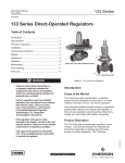
1
Bulletin 71.1:133
June 2013
133 Series Direct-Operated Regulators
W6803/IL
W1327/IL
TYPES 133H, 133L, AND 133Z REGULATORS
TYPE 133HP REGULATOR
Figure 1. 133 Series Direct-Operated Regulators
Features
• Wide Pressure Range Capability with Single
Regulator—Type 133H may also use Type 133L
springs, allowing pressure settings to be varied
between 2 inches w.c. and 10 psig / 5 mbar and
0.69 bar by changing springs.
• Types 133L, 133H, and 133HP Suitable for
Monitoring Applications—O-ring stem seal on
Types 133L, 133H, and 133HP isolates body
pressure from controlled pressure.
• Excellent Shock Characteristics and Fast
Speed of Response—Due to two-way stabilizer
vent valve, which vents the spring case more
rapidly than conventional vents, lag in diaphragm
and valve disk movement is minimized.
• No Seat-to-Seat Adjustment Required—Balanced
single-port design eliminates necessity for seat-toseat adjustments to achieve bubble-tight shutoff.
• Easy Access to Trim Parts—Valve seat, disk, and
cage easily removed with body remaining in line
andwithoutdisassemblyofactuatorportion;orifice
is not threaded in.
• Reusable Pressure Seals—O-rings used for
pressure seals, unlike gaskets, are not ordinarily
damaged by disassembling the regulator.
• Resistance to Piping Stresses—Steel
constructions are available to help resist pipe stresses.
D100118X012
• Bubble-Tight Shutoff—Single-port construction,
large diaphragm area, and light-rate springs along
with disk material and seat design provide low
lock-up pressures.
• Spring and Diaphragm Effects Minimized—
Boosting system provides excellent performance
overawiderangeofflowconditions.
www.fisherregulators.com
Bulletin 71.1:133
Specifications
The Specifications section lists the specifications for the Type 133 Series direct-operated regulators. Factory
specification is stamped on the nameplate fastened on the regulator at the factory.
Available Constructions
Type 133H: Direct-operated regulator for inlet pressures to 60 psig / 4.1 bar and outlet pressures from 1.5 to 10 psig / 0.10 to 0.69 bar, three ranges.
Type 133HP: Direct-operated regulator for inlet pressures to 150 psig / 10.3 bar and outlet
pressures from 2 to 60 psig / 0.14 to 4.1 bar, seven ranges.
Type 133L: Direct-operated regulator for inlet pressures to 60 psig / 4.1 bar and outlet pressures from 2 inches w.c. to 2 psig / 5 mbar to 0.14 bar, six ranges.
Type 133Z Zero Governor: Direct-operated regulator for inlet pressures to 20 psig / 1.4 bar and outlet pressures from -1 to 4-inches w.c. /
-2.5 to 10 mbar, two ranges.
Body Size and End Connection Styles
BODY SIZE
BODY MATERIAL
Inch
DN
Cast Iron Body
WCC Steel Body
2
50
NPT or CL125 FF Flanged
NPT or CL150 RF Flanged
Maximum Inlet Pressures(1)
See Table 2
Outlet Pressure Ranges(1)
See Table 1
Maximum Outlet Pressures(1)
See Table 2
Pressure Registration
External; downstream control line is required
Control Line Connection
Types 133H, 133L, and 133Z: 3/4 NPT internal connection will be positioned directly over body outlet (standard position) or 90° right or left of standard position if specified.
Type 133HP: 1/4 NPT Internal connection positioned directly over body outlet.
Vent Connection
Types 133H, 133L, and 133Z: 1 NPT internal with screen; standard position is in line with control line connection directly over body outlet. Vent will always be positioned over the control line connection.
Type 133HP: 1/2 NPT internal connection positioned directly over body inlet with a Fisher® Type Y602-7 vent assembly.
Temperature Capabilities(1)
-20 to 150°F / -29 to 66°C
Flow Capacities
See Tables 3 through 10
Wide-Open Flow Coefficients
CAPACITY
WIDE-OPEN Cg FOR
RELIEF VALVE SIZING
REPRESENTATIVE
C1
25%(2)
40%(2)
60%(2)
100%
490
760
1150
1800
28.2
29.1
31.8
35.0
Construction Materials
Body: Cast iron or WCC Steel
Orifice and Cage: Aluminum
Valve Disk: Aluminum/Neoprene (CR) or
Aluminum/Fluorocarbon (FKM)(3)
O-rings: Nitrile (NBR) or Fluorocarbon (FKM)(3)
Diaphragms:
Nitrile (NBR)/Nylon (PA) (Neoprene (CR) in actuator)
or Fluorocarbon (FKM)(3)/Polymer Thermoplastic
Guide Bushing: Nylon (PA)
Stem and Stem Sleeve: Stainless steel
Diaphragm Plate: Steel
Balancing Diaphragm Plate: Plated steel
Spring Case and Closing Cap:
Type 133HP: Cast Iron
Types 133H, 133L, and 133Z: Aluminum
Lower Casing:
Types 133H, 133L, and 133Z: Aluminum
Type 133HP: Steel
Adjusting Screw:
Types 133H and 133Z: Brass
Type 133L: Aluminum
Type 133HP: Steel
Optional Restriction Collar: Aluminum
Approximate Shipping Weight
Types 133H, 133L, and 133Z NPT
End Connections: 35 pounds / 16 kg
Types 133H, 133L, and 133Z Flanged
End Connections: 40 pounds / 18 kg
Type 133HP NPT End Connections:
56.5 pounds / 26 kg
Type 133HP Flanged End Connections:
62.5 pounds / 28 kg
Option
Restriction collar to reduce wide-open capacity to approximately 25%, 40%, or 60% of standard wide-open capacity.
1. The pressure/temperature limits in this Bulletin or any applicable standard limitation should not be exceeded.
2. Using optional restriction collar.
3. Available for Types 133L and 133H only.
2
Bulletin 71.1:133
W1213-1/IL
W1212-1/IL
TYPE 133Z ZERO GOVERNOR
TYPE 133L LOW-PRESSURE REGULATOR
RESTRICTION COLLAR
IDENTIFICATION
GROOVE 1
ORIFICE
SET SCREW
CAGE
W2215-1
VALVE DISK
E-RING
TRIM PARTS WITH RESTRICTION COLLAR
(40% CAPACITY COLLAR IS SHOWN)
W1211-1
TYPE 133H WITHOUT
RESTRICTION COLLAR
1
IDENTIFICATION GROOVES:
25% CAPACITY COLLAR—NO GROOVES
40% CAPACITY COLLAR—ONE GROOVE
60% CAPACITY COLLAR—TWO GROOVES
Figure 2. Types 133Z, 133L, and 133H Regulators
3
Bulletin 71.1:133
Introduction
Description
The 133 Series direct-operated gas regulators, shown
in Figure 1 are primarily designed for industrial and
commercial applications supplying gas to furnaces,
burners, and other appliances. The 133 Series
balancing system enables the regulator to provide
accurate control of gas pressure for maximum
combustionefficiencydespitevaryinginletpressure
conditions. The single port construction provides
bubble-tight shutoff. An external downstream control
line is required for the operation of the regulator. Refer
to Table 1 for outlet pressure ranges of each type.
133 Series regulators are available in a 2 inch / DN 50
bodysizewitheitherNPTorflangedendconnections.
An optional restriction collar (Figure 2) can be installed
if wide-open capacity is too high for applications using
a relief valve as overpressure protection. The collar
reduces wide-open capacity to 25%, 40%, or 60% of
standard wide-open capacity.
Principle of Operation
Refer to the operational schematics in Figure 4. In
the 133 Series, downstream pressure is registered
under the diaphragm via the external control line and
is used as the operating medium. Increased demand
lowers the downstream pressure and allows the spring
to move the diaphragm and stem assembly down,
opening the valve disk and supplying more gas to the
downstream system. Decreased demand increases
the downstream pressure and moves the diaphragm
and stem assembly up, closing the valve disk and
decreasing the gas supply to the downstream system.
Boosting System
The 133 Series incorporates a balancing diaphragm
and a boosting system. When the regulator is locked
up, inlet pressure is registered on the top of the valve
disk and on the bottom of the balancing diaphragm
through registration holes in the top of the cage. Also,
downstream pressure is registered on the bottom
of the valve disk and on the top of the balancing
diaphragm through a passage formed by grooves in
the registration disk and an annular space between the
stem and stem sleeve.
Whenthevalvediskisopen,gasflowsfromtheinlet
over the edge of the valve disk to the outlet. Under
the valve disk near the registration disk, there is little
4
W6883/IL
Figure 3. Type 133HP Regulator
gasflow.Thegaspressureneartheregistrationdisk
ishigherthanitisintheflowpathwheregasvelocity
tends to lower the pressure. The higher pressure
near the disk is registered on the top of the balancing
diaphragm through the registration disk and the
annular space between the stem and stem sleeve.
This pressure registered on the top of the balancing
diaphragm aids downward disk travel and compensates
for spring and diaphragm effect. This improves
regulator rangeability and performance.
Two-Way Stabilizer Vent Valve on
Types 133H, 133L, and 133Z
When the regulator responds to an increase in
downstream pressure, the diaphragm moves upward.
As the diaphragm rises, movement of air forces the
lower vent stabilizer upward, carrying the upper
stabilizer with it (see Figure 5). This allows the air
above the diaphragm to vent to atmosphere rapidly
enough to minimize lag in diaphragm movement.
Asthediaphragmfalls,airrushesintheventtofill
the partial vacuum created, forcing the upper vent
June 2009
Bulletin 71.1:133 Type 133
Type 133L
Type 133HP
e 133L
CONTROL SPRING
DIAPHRAGM
INLET PRESSURE
DOWNSTREAM
OUTLET PRESSURE
ATMOSPHERIC PRESSURE
CONTROL LINE
LOADING PRESSURE
INTERMEDIATE PRESSURE
PILOT SUPPLY PRESSURE
VACUUM PRESSURE
TANK PRESSURE
VAPOR PRESSURE
BALANCING
RELIEF
PRESSURE
DIAPHRAGM
BOOST
PRESSURE
STEM
ORIFICE
VENT
ASSEMBLY
DIAPHRAGM
A6555
DOWNSTREAM
CONTROL LINE
VALVE DISK
REGISTRATION DISK
INLET PRESSURE
OUTLET PRESSURE
ATMOSPHERIC PRESSURE
BOOST PRESSURE
A6555
INLET PRESSURE
OUTLET PRESSURE
A6883
INLET PRESSURE
OUTLET PRESSURE
ATMOSPHERIC PRESSURE
ATMOSPHERIC PRESSURE
BOOST PRESSURE
BOOST PRESSURE
TYPE 133L REGULATOR
TYPE 133HP REGULATOR
Figure 4. Operational Schematics
stabilizeragainsttheorificeplate.Airflowingthrough
the webs of the upper stabilizer opens the lower
stabilizer (see Figure 5). With the regulator at steadystate conditions, both stabilizers are closed and only a
small hole is open to help stabilize normal operation.
Installation
The regulator may be installed in any position but is
normally installed with the actuator portion vertical
above the body portion. Flow through the body must
beinthedirectionindicatedbytheflowdirectionarrow
cast on the body portion. A downstream control line is
required for operation of the regulator.
A remote vent line may be required for some
installations. Vent openings must be protected against
the entrance of rain, snow, insects, or any other
foreign material that may plug the vent.
External dimensions are shown in Figure 9.
Overpressure Protection
As is the case with most regulators, the 133 Series
regulators have outlet pressure ratings that are
lower than the inlet pressure ratings. Some type of
Overpressure Protection is needed if the actual inlet
pressure ever exceeds the outlet pressure rating.
Maximum inlet and outlet pressures for the 133 Series
are given in Table 2. All models must be protected
against inlet pressure above the maximum emergency
inlet pressure (refer to Table 2).
Outlet pressure more than 3 psig / 0.21 bar for
Types 133H, 133L, and 133Z, or 40 psig / 2.8 bar for
Type 133HP over the outlet pressure setting of the
regulator may damage internal parts such as the
diaphragm plate and valve disk.
Regulator operation below these emergency pressure
limitations does not preclude the possibility of damage
5
Bulletin 71.1:133
Table 1. 133 Series Outlet Pressure Ranges, Control Springs
OUTLET PRESSURE RANGE
TYPE
CONTROL SPRINGS
psig
bar
Part Number
Color Code
133H(1)
1.5 to 3
2 to 5
5 to 10
0.10 to 0.21
0.14 to 0.34
0.34 to 0.69
1H975927032
10A9440X012
1J146927142
133HP(1)
2 to 5
4.5 to 10
6 to 20
16 to 30
26 to 40
36 to 50
45 to 60
0.14 to 0.34
0.31 to 0.69
0.41 to 1.4
1.1 to 2.1
1.8 to 2.8
2.5 to 3.4
3.1 to 4.1
133L(1) and 133H(2)
2 to 4 inches w.c.
3.5 to 6 inches w.c.
5 to 9 inches w.c.
8.5 to 18 inches w.c.
14 to 28 inches w.c.
0.75 to 2
-1 to 1 inch w.c.
Wire Diameter
mm
Inch
mm
Orange
Yellow
Blue
6.91
6.47
6.19
176
164
157
0.250
0.283
0.375
6.35
7.19
9.53
17B8632X012
17B8633X012
10C1238X012
10C1240X012
10C1241X012
10C1242X012
10C1243X012
Yellow
Orange
Silver
Red
Blue
Green
White
8.5
8.5
8.25
8.25
8.25
8.25
8.25
216
216
210
210
210
210
210
0.282
0.343
0.375
0.438
0.500
0.500
0.531
7.16
8.71
9.52
11.1
12.7
12.7
13.5
5 to 10 mbar
9 to 15 mbar
12 to 22 mbar
21 to 45 mbar
35 to 70 mbar
0.05 to 0.14
1D892527022
1D892627022
1D892727012
1D893227032
1D893327032
1H975827032
Brown
Red
Black
White
Green
Blue
6.13
7.53
7.88
7.5
7.25
7.09
156
191
200
191
184
180
0.109
0.112
0.130
0.156
0.182
0.225
2.77
2.84
3.30
3.96
4.62
5.72
-3 to 3 mbar
1K633427012
(Extension Spring)
Unpainted
2
50.8
0.075
1.91
Unpainted
2
50.8
0.075
1.91
0 to 10 mbar
1K633427012
(Extension Spring)
and
1D892527022
(Compression Spring)
Brown
6.13
156
0.109
2.77
133Z(1)
0 to 4 inches w.c.
Free Length
Inch
1. Pressure ranges shown are correct if the regulator is installed with the actuator portion above the body portion. If the regulator is installed with the actuator portion below the body, the
pressure ranges will be lowered by approximately 2 inches w.c. / 5 mbar for the Type 133L and by approximately 3 inches w.c. / 7 mbar for the Types 133H and 133Z.
2. If the 2 inches w.c. / 5 mbar to 2 psig / 0.14 bar springs (all 6 ranges) are used in the Type 133H, the pressure ranges will increase by approximately 1 inch w.c. / 2 mbar due to
the weight of the Type 133H parts (assuming that the actuator is installed above the body).
Table 2. Maximum Inlet and Outlet Pressures
TYPE NUMBER
PRESSURES
133H
133HP
psig
bar
Maximum Operating Inlet Pressure
60
4.1
psig
150
133L
bar
10.3
Maximum Emergency Inlet Pressure
125
8.6
Maximum Operating Outlet Pressure(1)
10
0.69
Maximum Outlet Pressure Over
Outlet Pressure Setting
3
0.21
Setpoint
plus 40
Setpoint
plus 2.8
Maximum Emergency Outlet
(Casing) Pressure
15
1.0
150
10.3
133Z
psig
bar
psig
bar
60
4.1
20
1.4
125
8.6
125
8.6
2
0.14
4 inches w.c.
10 mbar
3
0.21
3
0.21
15
1.0
15
1.0
1. With highest spring range available only.
from external sources or from debris in the gas line.
The regulator should be inspected for damage after
any overpressure condition. Complete instructions for
installation, operation, and maintenance are provided
with each regulator.
Capacity Data
Flow capacities for various inlet pressures and
outlet pressure settings are shown in Tables 3 to 10.
Capacities are in thousands of SCFH at 60°F and
14.7 psia and in thousands of Nm3/h at 0°C and
1.01325 bar of 0.6 specific gravity gas. To convert
6
to equivalent capacities of other gases, multiply the
SCFH values shown by the appropriate factor: air–
0.775; propane–0.628; butane–0.548; nitrogen–0.789.
For gases of other specific gravities, multiply the given
capacity by 0.775, and divide by the square root of
the appropriate specific gravity. Then, if capacity is
desired in Nm³/h at 0°C and 1.01325 bar, multiply
SCFH by 0.0268.
Note
For optimum performance, select the
lowest spring range that includes the
desired outlet pressure setting.
Bulletin 71.1:133
W1032-1/IL
W1902-1/IL
TWO-WAY STABILIZER VENT VALVE IN “UP” POSITION
AS DIAPHRAGM RISES
VENT VALVE IN “DOWN” POSITION
AS DIAPHRAGM LOWERS
Figure 5. Types 133H, 133L, and 133Z Stabilizer Vent
Forrestricted-capacityconstructions,determineflow
capacities for outlet pressure settings of 2 psig /
0.14 bar or less by multiplying the values from
Tables 3 to 10 by 25%, 40%, or 60% (depending upon
which restriction collar is selected). For pressure
settings over 2 psig / 0.14 bar, capacities are given
inTable6.Ifflowcapacitiesforinletpressures
lower than those shown are required, contact your
localSalesOffice.Therepresentativeregulating
Cg of 1650 may be used for regulator sizing of full
capacity constructions only if capacity table data is
not available. The representative regulating Cg is an
approximation only for pressure drops greater than
5 psi / 0.34 bar, because, at a given offset in controlled
pressure, the regulating Cg varies with the spring being
used with the pressure drop across the valve.
TodeterminecapacityusingtheflowcoefficientCg,
use the appropriate procedure below.
Critical Pressure Drops
Non-Critical Pressure Drops
For pressure drops lower than critical (absolute outlet
pressure greater than one-half of absolute
inlet pressure).
Q=
520
C P SIN
GT g 1
3417
C1
∆P
P1
DEG
where,
Q
P1
C g
G
T
C 1
P
=gasflowrate,SCFH
= absolute inlet pressure, psia (P1 gauge + 14.7)
=regulatingorwide-opengassizingcoefficient
=specificgravityofthegas
= absolute temperature of gas at inlet, °Rankine
=flowcoefficient
= pressure drop across the regulator, psi
For critical pressure drops (absolute outlet pressure
equal to or less than one-half of absolute inlet
pressure), use the following formula:
Q = (P1)(Cg)(1.29)
Table 3. Full-Capacity Type 133Z Regulated Flow in Thousands of SCFH of 0.6 Specific Gravity Gas at 14.7 psia and 60°F
1 inch w.c. / 3 mbar OUTLET PRESSURE SETTING(1) (EITHER SPRING RANGE)
INLET PRESSURE
0.5 inch w.c. / 1 mbar Droop
1 inch w.c. / 3 mbar Droop
psig
bar
SCFH
Nm3/h
SCFH
Nm3/h
8 inches w.c.
14 inches w.c.
1
2
20 mbar
35 mbar
0.07
0.14
2.4
4.1
6.5
11.5
0.06
0.11
0.17
0.31
5.1
7.4
12
18
0.14
0.20
0.32
0.48
5
10
20
0.34
0.69
1.4
22
44
76
0.59
1.18
2.04
32
50
78
0.86
1.34
2.09
1. Outlet pressure setting was made at approximately 10% of the maximum capacity for the listed conditions.
7
Bulletin 71.1:133
Table 4. Full-Capacity Type 133L Regulated Flow in Thousands of SCFH of 0.6 Specific Gravity Gas at 14.7 psia and 60°F
OUTLET PRESSURE SETTING(1), SPRING PART NUMBER, AND OUTLET PRESSURE RANGE
INLET
PRESSURE
psig
bar
4 inches w.c. /
10 mbar
1D892527022
2 to
4 inches w.c. /
5 to
10 mbar
6 inches w.c. /
15 mbar
1D892627022
3.5 to
6 inches w.c. /
8.7 to
15 mbar
7 inches w.c. /
17 mbar
1D892727012
5 to
9 inches w.c. /
12 to 22 mbar
1 inch w.c. /
3 mbar
Droop
1 inch w.c. /
3 mbar
Droop
1 inch w.c. /
3 mbar
Droop
SCFH Nm3/h SCFH Nm3/h SCFH
14 inches w.c. /
35 mbar
1D893227032
8.5 to
18 inches w.c. /
21 to 45 mbar
1 inch w.c. /
3 mbar
Droop
14 inches w.c. /
35 mbar
1D893327032
14 to 28 inches w.c. /
35 to 70 mbar
2 inch w.c /
5 mbar
Droop
1 inch w.c. /
3 mbar
Droop
1 psig / 0.07 bar
1D893327032
14 to 28 inches w.c. /
35 to 70 mbar
2 inch w.c. /
5 mbar
Droop
10%
Droop
2 psig / 0.14 bar
1H975827032
0.75 to 2 psig /
0.05 to 0.14 bar
20%
Droop
10%
Droop
20%
Droop
Nm3/h SCFH Nm3/h SCFH Nm3/h SCFH Nm3/h SCFH Nm3/h SCFH Nm3/h SCFH Nm3/h SCFH Nm3/h SCFH Nm3/h
1
2
3
0.07
0.14
0.21
14
20.8
26
0.38
0.56
0.70
13
20
24.5
0.35
0.54
0.66
12
17
21
0.32
0.46
0.56
5
8.2
12
0.13
0.22
0.32
8.4
15.2
19.5
0.22
0.41
0.52
----------
----------
----------
----------
---11.5
15.5
---0.31
0.42
---16
21.5
---0.43
0.58
------12.5
------0.34
------18.5
------0.50
5
10
20
0.34
0.69
1.4
35
52
78
0.94
1.39
2.09
33
52
77
0.88
1.39
2.06
32
48
79
0.86
1.29
2.12
16
34
69
0.43
0.91
1.85
28
45
76
0.75
1.21
2.04
14
26
60
0.38
0.70
1.61
23
38
69
0.62
1.02
1.85
24
37.5
70
0.64
1.00
1.88
31.5
44
77
0.84
1.18
2.06
20.5
38
62
0.55
1.02
1.66
28
46
76
0.75
1.23
2.04
30
40
50
60
2.1
2.8
3.4
4.1
101
124
146
170
2.71
3.32
3.91
4.56
100
122
144
168
2.68
3.27
3.86
4.50
100
124
145
166
2.68
3.32
3.89
4.45
91
109
130
155
2.44
2.92
3.48
4.15
97
116
136
161
2.60
3.11
3.64
4.32
87
107
132
152
2.33
2.87
3.54
4.07
93
115
137
158
2.49
3.08
3.67
4.23
90
110
127
149
2.41
2.95
3.40
3.99
101
122
145
167
2.71
3.27
3.89
4.48
87
105
124
145
2.33
2.81
3.32
3.89
101
121
145
170
2.71
3.24
3.89
4.56
1. Outlet pressure setting was made at approximately 10% of the maximum capacity for the listed conditions.
Table 5. Full-Capacity Type 133H Regulated Flow in Thousands of SCFH of 0.6 Specific Gravity Gas at 14.7 psia and 60°F
OUTLET PRESSURE SETTING(1), SPRING PART NUMBER, AND OUTLET PRESSURE RANGE
3 psig / 0.21 bar
1H975927032
1.5 to 3 psig /
0.10 to 0.21 bar
INLET
PRESSURE
psig
bar
10%
Droop
2 psig / 0.14 bar
10A9440X012
2 to 5 psig /
0.14 to 0.34 bar
20%
Droop
10%
Droop
5 psig / 0.34 bar
10A9440X012
2 to 5 psig /
0.14 to 0.34 bar
20%
Droop
10%
Droop
20%
Droop
10%
Droop
10 psig / 0.69 bar
1J146927142
5 to 10 psig /
0.34 to 0.69 bar
20%
Droop
10%
Droop
20%
Droop
SCFH
Nm3/h
SCFH
Nm3/h
SCFH
Nm3/h
SCFH
Nm3/h
SCFH
Nm3/h
SCFH
Nm3/h
SCFH
Nm3/h
SCFH
Nm3/h
SCFH
Nm3/h
SCFH
Nm3/h
3
5
7
0.21
0.34
0.48
---14
21.5
---0.38
0.58
---22
31
---0.59
0.83
6.5
11
13
0.17
0.30
0.35
11.5
18
22
0.31
0.48
0.59
------15.5
------0.42
------24
------0.64
------9
------0.24
------15
------0.40
----------
----------
----------
----------
10
15
20
0.69
1.0
1.4
28
40
52
0.75
1.07
1.39
42
57
72
1.13
1.53
1.93
15
25.5
35
0.40
0.68
0.94
27
39
52
0.72
1.04
1.39
24
35
46
0.64
0.94
1.23
35
51
67
0.94
1.37
1.80
14
19
24
0.38
0.51
0.64
22
31.5
41
0.59
0.84
1.10
---21
31
---0.56
0.83
---35
51
---0.94
1.37
30
40
50
60
2.1
2.8
3.4
4.1
76
98
118
136
2.04
2.63
3.16
3.64
96
119
141
165
2.57
3.19
3.78
4.42
49
66
84
104
1.31
1.77
2.25
2.79
73
97
112
132
1.96
2.60
3.00
3.54
68
88
103
122
1.82
2.36
2.76
3.27
95
117
138
156
2.55
3.14
3.70
4.18
35
44
57
65
0.94
1.18
1.53
1.74
58
73
89
106
1.55
1.96
2.38
2.84
44
56
74
91
1.18
1.50
1.98
2.44
74
97
117
136
1.98
2.60
3.14
3.64
1. Outlet pressure setting was made at approximately 10% of the maximum capacity for the listed conditions.
8
5 psig / 0.34 bar
1J146927142
5 to 10 psig /
0.34 to 0.69 bar
Bulletin 71.1:133
OUTLET PRESSURE,
psig / bar
OUTLET PRESSURE,
inch w.c. / mbar
CAPACITY AND REGULATION
2 inch / DN 50 TYPE 133Z
SPRING COMPRESSION - 1D892527022 EXTENSION - 1K633427012
SETPOINT: INLET PRESSURE: 1 psig / 0.07 bar
OUTLET PRESSURE: 1 inch w.c. / 2 mbar
FLOW: 3000 SCFH / 80.4 Nm3/h
3/7
2/5
1/2
0/0
1 psig /
0.07 bar
0/
0
21A0871–A
10 /
0.3
2 psig /
0.14 bar
20 /
0.5
30 /
0.8
5 psig /
0.34 bar
40 /
1.0
10 psig /
0.69 bar
50 /
1.3
60 /
1.6
1.2 / 0.08
1.0 / 0.07
0.8 / 0.06
0.6 / 0.04
0.4 / 0.03
20 psig /
1.4 bar
70 /
1.9
CAPACITY AND REGULATION
2 inch / DN 50 TYPE 133L SPRING 1D893327032
SETPOINT: INLET PRESSURE: 40 psig / 2.8 bar
OUTLET PRESSURE: 1 psig / 0.07 bar
FLOW: 11,000 SCFH / 295 Nm3/h
20 psig / 30 psig / 40 psig / 50 psig / 60 psig /
1.4 bar 2.1 bar 2.8 bar 3.4 bar
4.1 bar
0.2 / 0.01
80 /
2.1
90 /
2.4
0/
0
21A0868–A
20 /
0.5
10 / 25
8 / 20
6 / 15
4 / 10
0/
0
21A0865–A
OUTLET PRESSURE,
inch w.c. / mbar
1 psig /
0.07 bar
10 / 25
2 psig /
0.14 bar
3 psig /
0.21 bar
8/
12 /
16 /
20 /
24 /
28 /
32 /
0.2
0.3
0.4
0.5
0.6
0.8
0.9
3
FLOW RATE IN THOUSANDS OF SCFH / Nm /h
0.6 SPECIFIC GRAVITY GAS AT 14.7 psia AND 60°F
36 /
1.0
8 / 20
6 / 15
4 / 10
10 psig /
0.69 bar
20 psig /
1.4 bar
30 psig /
2.1 bar
40 psig /
2.8 bar
2 / 0.14
21A0869–A
CAPACITY AND REGULATION
2 inch / DN 50 TYPE 133L SPRING 1D892727012
SETPOINT: INLET PRESSURE: 40 psig / 2.8 bar
OUTLET PRESSURE: 7 inch w.c. / 17 mbar
FLOW: 11,000 SCFH / 295 Nm3/h
2/5
100 /
2.7
120 /
3.2
140 /
3.8
160 / 180 /
4.3
4.8
3 / 0.21
5 psig /
0.34 bar
4/
0.1
80 /
2.1
CAPACITY AND REGULATION
2 inch / DN 50 TYPE 133L SPRING 1D893327032
SETPOINT: INLET PRESSURE: 40 psig / 2.8 bar
OUTLET PRESSURE: 1 psig / 0.07 bar
FLOW: 11,000 SCFH / 295 Nm3/h
OUTLET PRESSURE,
psig / bar
CAPACITY AND REGULATION
2 inch / DN 50 TYPE 133L SPRING 1D892727012
SETPOINT: INLET PRESSURE: 2 psig / 0.14 bar
OUTLET PRESSURE: 7 inch w.c. / 17 mbar
FLOW: 3100 SCFH / 83.08 Nm3/h
2/5
60 /
1.6
FLOW RATE IN THOUSANDS OF SCFH / Nm3/h
0.6 SPECIFIC GRAVITY GAS AT 14.7 psia AND 60°F
1 / 0.07
20 psig /
1.4 bar
0/
0
60 psig /
4.1 bar
140 / 160 /
40 /
60 /
80 /
100 / 120 /
3.8
4.3
1.1
1.6
2.1
2.7
3.2
FLOW RATE IN THOUSANDS OF SCFH / Nm3/h
0.6 SPECIFIC GRAVITY GAS AT 14.7 psia AND 60°F
20 /
0.5
180 /
4.8
6 / 0.41
5 / 0.35
4 / 0.28
3 / 0.21
50 psig / 60 psig /
3.4 bar
4.1 bar
2 / 0.14
21A0866
40 psig /
2.8 bar
CAPACITY AND REGULATION
2 inch / DN 50 TYPE 133H SPRING 10A9440X012
SETPOINT: INLET PRESSURE: 40 psig / 2.8 bar
OUTLET PRESSURE: 5 psig / 0.34 bar
FLOW: 11,000 SCFH / 295 Nm3/h
OUTLET PRESSURE,
psig / bar
OUTLET PRESSURE,
inch w.c. / mbar
FLOW RATE IN THOUSANDS OF SCFH / Nm3/h
0.6 SPECIFIC GRAVITY GAS AT 14.7 psia AND 60°F
40 /
1.1
20 psig / 30 psig / 40 psig / 50 psig / 60 psig /
1.4 bar 2.1 bar
2.8 bar 3.4 bar 4.1 bar
21A0870–A
20 /
0.5
40 /
1.1
60 /
80 /
100 / 120 / 140 / 160 /
1.6
2.1
2.7
3.2
3.8
4.3
FLOW RATE IN THOUSANDS OF SCFH / Nm3/h
0.6 SPECIFIC GRAVITY GAS AT 14.7 psia AND 60°F
OUTLET PRESSURE,
inch w.c. / mbar
0/
0
180 /
4.8
0/
0
20 /
0.5
40 /
60 /
80 /
100 / 120 / 140 / 160 /
1.1
1.6
2.1
2.7
3.2
3.8
4.3
FLOW RATE IN THOUSANDS OF SCFH / Nm3/h
0.6 SPECIFIC GRAVITY GAS AT 14.7 psia AND 60°F
180 /
4.8
CAPACITY AND REGULATION
2 inch / DN 50 TYPE 133L SPRING 1D893227032
SETPOINT: INLET PRESSURE: 40 psig / 2.8 bar
OUTLET PRESSURE: 14 inch w.c. / 35 mbar
FLOW: 11,000 SCFH / 295 Nm3/h
18 / 45
16 / 40
14 / 34
12 / 30
10 / 25
8 / 20
10 psig /
0.69 bar
6 / 15
21A0867–A
C0744/IL
0/
0
20 /
0.5
40 /
1.1
20 psig /
1.4 bar
60 /
1.6
80 /
2.1
40 psig /
2.8 bar
100 /
2.7
120 /
3.2
60 psig /
4.1 bar
140 /
3.8
160 /
4.3
180
4.8
FLOW RATE IN THOUSANDS OF SCFH / Nm3/h
0.6 SPECIFIC GRAVITY GAS AT 14.7 psia AND 60°F
Figure 6. Capacity Curves — Full-Capacity Constructions
9
CAPACITY AND REGULATION
2 inch / DN 50 TYPE 133L
SPRING 1D892727012
25% CAPACITY TRIM
SETPOINT: INLET PRESSURE: 20 psig / 1.4 bar
OUTLET PRESSURE: 7 inches w.c. / 17 mbar
FLOW: 2140 SCFH / 57.35 Nm3/h
12 / 30
OUTLET PRESSURE,
psig / bar
OUTLET PRESSURE,
inch w.c. / mbar
Bulletin 71.1:133
8 / 20
4 / 10
10 psig /
0.69 bar
23A1336–A
0/
0
5/
0.1
10 /
0.3
15 /
0.4
20 psig /
1.4 bar
20 /
0.5
25 /
0.7
40 psig /
2.8 bar
30 /
0.8
60 psig /
4.1 bar
35 /
0.9
40 /
1.1
CAPACITY AND REGULATION
2 inch / DN 50 TYPE 133L
SPRING 1H975827032
25% CAPACITY TRIM
SETPOINT: INLET PRESSURE: 20 psig / 1.4 bar
OUTLET PRESSURE: 2 psig / 0.14 bar
FLOW: 2140 SCFH / 57.35 Nm3/h
3.0 / 0.21
2.0 / 0.14
1.0 / 0.07
5.0 psig / 10 psig / 20 psig /
0.34 bar 0.69 bar 1.4 bar
23A1332–A
45 /
1.2
0/
0
5/
0.1
FLOW RATE IN THOUSANDS OF SCFH /
0.6 SPECIFIC GRAVITY GAS AT 14.7 psia AND 60°F
8 / 20
0/
0
10 /
0.3
10 psig / 20 psig /
0.69 bar 1.4 bar
40 psig /
2.8 bar
20 /
0.5
50 /
1.3
30 /
0.8
40 /
1.0
60 psig /
4.1 bar
60 /
1.6
70 /
1.9
3.0 / 0.21
90 /
2.4
0/
0
10 /
0.3
8 / 20
10 psig / 20 psig /
0.69 bar 1.4 bar
0/
0
15 /
0.4
30 /
0.8
45 /
1.2
60 /
1.6
40 psig /
2.8 bar
75 /
2.0
120 /
3.2
135 /
3.6
Nm3/h
FLOW RATE IN THOUSANDS OF SCFH /
0.6 SPECIFIC GRAVITY GAS AT 14.7 psia AND 60°F
Figure 7. Capacity Curves — Restricted Capacity Constructions
10
3.0 / 0.21
20 /
0.5
30 /
0.8
40 /
1.0
50 /
1.3
60 /
1.6
70 /
1.9
80 /
2.1
90 /
2.4
2.0 / 0.14
5.0 psig / 10 psig / 20 psig / 40 psig / 60 psig /
0.34 bar 0.69 bar 1.4 bar
2.8 bar
4.1 bar
23A1335–A
105 /
2.8
45 /
1.2
CAPACITY AND REGULATION
2 inch / DN 50 TYPE 133L
SPRING 1H975827032
60% CAPACITY TRIM
SETPOINT: INLET PRESSURE: 20 psig / 1.4 bar
OUTLET PRESSURE: 2 psig / 0.14 bar
FLOW: 4900 SCFH / 131 Nm3/h
1.0 / 0.07
60 psig /
4.1 bar
90 /
2.4
40 /
1.1
FLOW RATE IN THOUSANDS OF SCFH /
0.6 SPECIFIC GRAVITY GAS AT 14.7 psia AND 60°F
CAPACITY AND REGULATION
2 inch / DN 50 TYPE 133L
SPRING 1D892727012
60% CAPACITY TRIM
SETPOINT: INLET PRESSURE: 20 psig / 1.4 bar
OUTLET PRESSURE: 7 inches w.c. / 17 mbar
FLOW: 4900 SCFH / 131 Nm3/h
4 / 10
35 /
0.9
Nm3/h
OUTLET PRESSURE,
psig / bar
OUTLET PRESSURE,
inch w.c. / mbar
FLOW RATE IN THOUSANDS OF SCFH /
0.6 SPECIFIC GRAVITY GAS AT 14.7 psia AND 60°F
23A1337–A
C0745/IL
30 /
0.8
5.0 psig / 10 psig / 20 psig / 40 psig / 60 psig /
0.34 bar 0.69 bar 1.4 bar
2.8 bar
4.1 bar
Nm3/h
12 / 30
25 /
0.7
2.0 / 0.14
23A1333–A
80 /
2.1
20 /
0.5
CAPACITY AND REGULATION
2 inch / DN 50 TYPE 133L
SPRING 1H975827032
40% CAPACITY TRIM
SETPOINT: INLET PRESSURE: 20 psig / 1.4 bar
OUTLET PRESSURE: 2 psig / 0.14 bar
FLOW: 2900 SCFH / 77.72 Nm3/h
1.0 / 0.07
4 / 10
23A1334–A
15 /
0.4
FLOW RATE IN THOUSANDS OF SCFH /
0.6 SPECIFIC GRAVITY GAS AT 14.7 psia AND 60°F
CAPACITY AND REGULATION
2 inch / DN 50 TYPE 133L
SPRING 1D892727012
40% CAPACITY TRIM
SETPOINT: INLET PRESSURE: 20 psig / 1.4 bar
OUTLET PRESSURE: 7 inches w.c. / 17 mbar
FLOW: 2900 SCFH / 77.72 Nm3/h
12 / 30
10 /
0.3
60 psig /
4.1 bar
Nm3/h
OUTLET PRESSURE,
psig / bar
OUTLET PRESSURE,
inch w.c. / mbar
Nm3/h
40 psig /
2.8 bar
0/
0
15 /
0.4
30 /
0.8
45 /
1.2
60 /
1.6
75 /
2.0
90 /
2.4
105 /
2.8
120 /
3.2
Nm3/h
FLOW RATE IN THOUSANDS OF SCFH /
0.6 SPECIFIC GRAVITY GAS AT 14.7 psia AND 60°F
135 /
3.6
Bulletin 71.1:133
Table 6. Restricted-Capacity Type 133H Regulated Flow in Thousands of SCFH of 0.6 Specific Gravity Gas at 14.7 psia and 60°F
OUTLET PRESSURE SETTING(1), SPRING PART NUMBER, AND OUTLET PRESSURE RANGE
25% Capacity
INLET
PRESSURE
psig
5 psig / 0.34 bar
10A9440X012
2 to 5 psig /
0.14 to 0.34 bar
10%
Droop
bar
40% Capacity
10 psig / 0.69 bar
1J146927142
5 to 10 psig /
0.34 to 0.69 bar
20%
Droop
10%
Droop
5 psig / 0.34 bar
10A9440X012
2 to 5 psig /
0.14 to 0.34 bar
20%
Droop
10%
Droop
60% Capacity
10 psig / 0.69 bar
1J146927142
5 to 10 psig /
0.34 to 0.69 bar
20%
Droop
10%
Droop
5 psig / 0.34 bar
10A9440X012
2 to 5 psig /
0.14 to 0.34 bar
20%
Droop
10%
Droop
10 psig / 0.69 bar
1J146927142
5 to 10 psig /
0.34 to 0.69 bar
20%
Droop
10%
Droop
20%
Droop
SCFH Nm3/h SCFH Nm3/h SCFH Nm3/h SCFH Nm3/h SCFH Nm3/h SCFH Nm3/h SCFH Nm3/h SCFH Nm3/h SCFH Nm3/h SCFH Nm3/h SCFH Nm3/h SCFH Nm3/h
7
10
15
20
40
60
0.48
0.69
1.0
1.4
2.8
4.1
8.0
12.3
---20.8
33.5
45.5
0.21
0.33
---0.56
0.90
1.22
9.0
13.0
---21.2
33.5
45.5
0.24
0.35
---0.57
0.90
1.22
------13.0
17.5
33.0
45.5
------0.35
0.47
0.88
1.22
------15.5
20.0
33.5
45.5
------0.42
0.54
0.90
1.22
11.0
16.5
---31.5
52.0
72.7
0.30
0.44
---0.84
1.39
1.95
15.0
20.0
---33.5
53.2
72.7
0.40
0.54
---0.90
1.43
1.95
------16.5
23.5
46.0
67.0
------0.44
0.63
1.23
1.80
------23.5
30.5
53.2
72.7
------0.63
0.82
1.43
1.95
13.0
20.0
---36.0
70.0
105
0.35
0.54
---0.96
1.88
2.81
17.0
25.0
---46.5
77.5
107
0.46
0.67
---1.25
2.08
2.87
------20.0
29.0
57.0
87.0
------0.54
0.78
1.53
2.33
------29.5
39.5
74.5
107
------0.79
1.06
2.00
2.87
1. Outlet pressure setting was made at approximately 10% of the maximum capacity for the listed conditions.
Table 7. Type 133HP Regulator 100% Capacities in Thousands of SCFH of 0.6 Specific Gravity Gas at 14.7 psia and 60°F
OUTLET PRESSURE
RANGE, CONTROL
SPRING NUMBER,
AND COLOR
OUTLET PRESSURE
SETTING(1)
2-INCH / DN 50 BODY SIZE
1.91-INCH / 48.5 mm ORIFICE SIZE
INLET
PRESSURE
Droop from Setpoint
10%
psig
2
30%
bar
psig
bar
SCFH
0.14
10
20
40
60
80
100
125
150
0.69
1.4
2.8
4.1
5.5
6.9
8.6
10.3
10.4
16.4
27.0
37.1
47.2
57.1
69.5
82.0
0.28
0.44
0.72
0.99
1.26
1.53
1.86
2.20
18.9
29.8
49.1
67.5
85.7
103.9
126.5
149.1
0.51
0.80
1.32
1.81
2.30
2.78
3.39
4.00
27.5
43.3
71.2
97.9
124.3
150.6
183.4
216.3
0.74
1.16
1.91
2.62
3.33
4.04
4.92
5.80
0.34
10
20
40
60
80
100
125
150
0.69
1.4
2.8
4.1
5.5
6.9
8.6
10.3
20.2
35.1
59.6
82.4
104.9
127.2
155.0
182.7
0.54
0.94
1.60
2.21
2.81
3.41
4.15
4.90
41.5
71.7
121.3
167.9
213.6
258.9
315.4
371.8
1.11
1.92
3.25
4.50
5.72
6.94
8.45
9.96
42.8
72.3
121.5
168.0
213.6
258.9
315.4
371.8
1.15
1.94
3.26
4.50
5.72
6.94
8.45
9.96
2 to 5 psig /
0.14 to 0.34 bar
17B8632X012
Yellow
5
20%
Nm3/h
SCFH
Nm3/h
SCFH
Nm3/h
1. Outlet pressure setting was made at approximately 10% of the maximum capacity for the listed conditions.
Gray areas indicate maximum flow capacity.
- continued -
11
Bulletin 71.1:133
Table 7. Type 133HP Regulator 100% Capacities in Thousands of SCFH of 0.6 Specific Gravity Gas at 14.7 psia and 60°F
OUTLET PRESSURE
RANGE, CONTROL
SPRING NUMBER,
AND COLOR
OUTLET PRESSURE
SETTING(1)
2-INCH / DN 50 BODY SIZE
1.91-INCH / 48.5 mm ORIFICE SIZE
INLET
PRESSURE
Droop from Setpoint
10%
psig
5
psig
bar
SCFH
0.34
10
20
40
60
80
100
125
150
0.69
1.4
2.8
4.1
5.5
6.9
8.6
10.3
11.4
19.6
33.0
45.7
58.1
70.5
85.8
101.2
0.31
0.52
0.88
1.22
1.56
1.89
2.30
2.71
21.4
36.4
61.3
84.7
107.7
130.6
159.0
187.5
0.57
0.98
1.64
2.27
2.89
3.50
4.26
5.02
32.0
53.4
89.6
123.7
157.3
190.7
232.2
273.8
0.86
1.43
2.40
3.32
4.22
5.11
6.22
7.34
0.69
25
30
40
60
80
100
125
150
1.7
2.1
2.8
4.1
5.5
6.9
8.6
10.3
40.3
47.1
59.9
84.0
107.4
130.4
159.0
187.5
1.08
1.26
1.60
2.25
2.88
3.50
4.26
5.02
80.5
93.9
119.1
166.8
213.0
258.7
315.4
371.8
2.16
2.52
3.19
4.47
5.71
6.93
8.45
9.96
81.7
94.8
119.7
167.1
213.2
258.8
315.4
371.8
2.19
2.54
3.21
4.48
5.71
6.94
8.45
9.96
0.69
15
20
40
60
80
100
125
150
1.0
1.4
2.8
4.1
5.5
6.9
8.6
10.3
16.4
22.1
39.9
55.9
71.4
86.8
106.0
125.0
0.44
0.59
1.07
1.50
1.91
2.33
2.84
3.35
32.0
42.2
75.4
105.0
134.0
163.0
199.0
235.0
0.86
1.13
2.02
2.81
3.59
4.37
5.33
6.30
51.9
67.7
111.0
155.0
198.0
240.0
292.0
344.0
1.39
1.81
2.98
4.15
5.31
6.43
7.83
9.22
1.4
25
30
40
60
80
100
125
150
1.7
2.1
2.8
4.1
5.5
6.9
8.6
10.3
38.8
50.3
69.4
102.0
133.0
162.0
198.0
234.0
1.39
1.81
2.98
4.15
5.31
6.43
7.83
9.22
65.0
82.3
112.0
163.0
211.0
257.0
315.0
372.0
1.74
2.21
3.00
4.37
5.66
6.89
8.44
9.97
70.0
86.0
114.0
164.0
211.0
258.0
315.0
372.0
1.88
2.30
3.06
4.40
5.66
6.91
8.44
9.97
1.4
25
30
40
60
80
100
125
150
1.7
2.1
2.8
4.1
5.5
6.9
8.6
10.3
24.8
31.8
43.5
63.8
83.0
101.0
124.0
146.0
0.66
0.85
1.17
1.71
2.22
2.71
3.23
3.91
50.4
62.6
84.0
122.0
158.0
192.0
235.0
277.0
1.35
1.68
2.25
3.27
4.23
5.15
6.30
7.42
70.0
86.0
114.0
164.0
211.0
258.0
315.0
372.0
1.88
2.30
3.06
4.40
5.66
6.91
8.44
9.97
2.1
35
40
60
80
100
125
150
2.4
2.8
4.1
5.5
6.9
8.6
10.3
43.0
53.8
88.0
117.0
145.0
178.0
211.0
1.15
1.44
2.36
3.14
3.89
4.77
5.66
80.6
98.4
156.0
207.0
255.0
313.0
371.0
2.16
2.64
4.18
5.55
6.83
8.39
9.94
88.2
104.0
159.0
208.0
256.0
314.0
371.0
2.36
2.79
4.26
5.57
6.86
8.42
9.94
17B8633X012
Orange
10
6 to 20 psig /
0.41 to 1.4 bar
10C1238X012
Silver
20
20
16 to 30 psig /
1.1 to 2.1 bar
10C1240X012
Red
30
1. Outlet pressure setting was made at approximately 10% of the maximum capacity for the listed conditions.
Gray areas indicate maximum flow capacity.
- continued -
12
30%
bar
4.5 to 10 psig /
0.31 to 0.69 bar
10
20%
Nm3/h
SCFH
Nm3/h
SCFH
Nm3/h
Bulletin 71.1:133
Table 7. Type 133HP Regulator 100% Capacities in Thousands of SCFH of 0.6 Specific Gravity Gas at 14.7 psia and 60°F (continued)
OUTLET PRESSURE
RANGE, CONTROL
SPRING NUMBER,
AND COLOR
OUTLET
PRESSURE
SETTING(1)
30
40
bar
SCFH
2.1
35
40
60
80
100
125
150
2.4
2.8
4.1
5.5
6.9
8.6
10.3
28.9
35.7
57.5
76.4
94.3
116.0
137.0
0.78
0.96
1.54
2.05
2.53
3.11
3.67
59.6
71.0
110.0
146.0
179.0
220.0
260.0
1.60
1.90
2.95
3.91
4.80
5.90
6.97
88.2
104.0
159.0
208.0
256.0
314.0
371.0
2.36
2.79
4.26
5.57
6.86
8.42
9.94
2.8
45
50
60
80
100
125
150
3.1
3.4
4.1
5.5
6.9
8.6
10.3
43.5
52.6
68.4
95.4
120.0
149.0
177.0
1.17
1.41
1.83
2.56
3.22
3.99
4.74
96.2
114.0
146.0
186.0
232.0
287.0
341.0
2.58
3.06
3.91
4.98
6.22
7.69
9.14
106.0
122.0
151.0
204.0
253.0
312.0
370.0
2.84
3.27
4.05
5.47
6.78
8.36
9.92
2.8
45
50
60
80
100
125
150
3.1
3.4
4.1
5.5
6.9
8.6
10.3
36.2
43.4
56.2
78.1
97.9
122.0
145.0
0.97
1.16
1.51
2.09
2.62
3.27
3.89
76.1
88.1
110.0
150.0
187.0
232.0
276.0
2.04
2.36
2.95
4.02
5.01
6.22
7.40
106.0
122.0
151.0
204.0
253.0
312.0
370.0
2.84
3.27
4.05
5.47
6.78
8.36
9.92
3.4
55
60
80
100
125
150
3.8
4.1
5.5
6.9
8.6
10.3
50.4
59.5
90.2
116.0
147.0
176.0
1.35
1.60
2.42
3.11
3.94
4.72
112.0
130.0
191.0
227.0
283.0
338.0
3.00
3.48
5.12
6.08
7.58
9.06
124.0
141.0
197.0
248.0
309.0
368.0
3.32
3.78
5.28
6.65
8.28
9.86
3.4
55
60
80
100
125
150
3.8
4.1
5.5
6.9
8.6
10.3
43.5
51.0
76.9
99.0
125.0
149.0
1.17
1.37
2.06
2.65
3.35
3.99
92.7
105.0
151.0
191.0
239.0
285.0
2.48
2.81
4.05
5.12
6.40
7.64
124.0
141.0
197.0
248.0
309.0
368.0
3.32
3.78
5.28
6.65
8.28
9.86
4.1
65
70
80
100
125
150
4.5
4.8
5.5
6.9
8.6
10.3
57.5
66.5
83.2
112.0
144.0
174.0
1.54
1.78
2.23
3.00
3.86
4.66
127.0
146.0
179.0
236.0
280.0
336.0
3.40
3.91
4.80
6.32
7.50
9.00
143.0
159.0
188.0
242.0
305.0
365.0
3.83
4.26
5.04
6.49
8.17
9.78
10C1242X012
Green
50
50
10C1243X012
60
30%
psig
Blue
40
20%
bar
10C1241X012
White
Droop from Setpoint
Nm3/h
26 to 40 psig /
1.8 to 2.8 bar
45 to 60 psig /
3.1 to 4.1 bar
INLET
PRESSURE
10%
psig
36 to 50 psig /
2.5 to 3.4 bar
2-INCH / DN 50 BODY SIZE
1.91-INCH / 48.5 mm ORIFICE SIZE
SCFH
Nm3/h
SCFH
Nm3/h
1. Outlet pressure setting was made at approximately 10% of the maximum capacity for the listed conditions.
Gray areas indicate maximum flow capacity.
13
Bulletin 71.1:133
Table 8. Type 133HP Regulator 25% Capacities in Thousands of SCFH of 0.6 Specific Gravity Gas at 14.7 psia and 60°F
OUTLET PRESSURE
RANGE, CONTROL
SPRING NUMBER,
AND COLOR
OUTLET
PRESSURE
SETTING(1)
2-INCH / DN 50 BODY SIZE
1.91-INCH / 48.5 mm ORIFICE SIZE
INLET
PRESSURE
Droop from Setpoint
10%
psig
2
psig
bar
SCFH
0.14
10
20
40
60
80
100
125
150
0.69
1.4
2.8
4.1
5.5
6.9
8.6
10.3
4.0
6.4
10.5
14.5
18.4
22.3
27.2
32.0
0.11
0.17
0.28
0.39
0.49
0.60
0.73
0.86
7.8
12.5
20.6
28.4
36.0
43.7
53.2
62.7
0.21
0.34
0.55
0.76
0.97
1.17
1.43
1.68
13.4
12.2
34.9
48.1
61.1
74.0
90.1
106.2
0.36
0.33
0.94
1.29
1.64
1.98
2.42
2.85
0.34
10
20
40
60
80
100
125
150
0.69
1.4
2.8
4.1
5.5
6.9
8.6
10.3
8.3
14.9
25.4
35.2
44.8
54.3
66.2
78.1
0.22
0.40
0.68
0.94
1.20
1.46
1.77
2.09
11.5
20.3
34.6
47.9
61.0
74.0
90.1
106.2
0.31
0.54
0.93
1.28
1.64
1.98
2.42
2.85
11.9
20.5
34.7
48.0
61.0
74.0
90.1
106.2
0.32
0.55
0.93
1.29
1.64
1.98
2.42
2.85
0.34
10
20
40
60
80
100
125
150
0.69
1.4
2.8
4.1
5.5
6.9
8.6
10.3
4.4
7.8
13.3
18.4
23.4
28.4
34.6
40.8
0.12
0.21
0.36
0.49
0.63
0.76
0.93
1.09
8.7
15.4
26.1
36.2
46.1
55.9
68.1
80.2
0.23
0.41
0.70
0.97
1.24
1.50
1.83
2.15
11.9
20.5
34.7
48.0
61.0
74.0
90.1
106.2
0.32
0.55
0.93
1.29
1.64
1.98
2.42
2.85
0.69
25
30
40
60
80
100
125
150
1.7
2.1
2.8
4.1
5.5
6.9
8.6
10.3
17.0
19.9
25.5
35.9
45.9
55.8
68.0
80.2
0.46
0.53
0.68
0.96
1.23
1.50
1.82
2.15
22.6
26.5
33.8
47.5
60.8
73.9
90.1
106.2
0.61
0.71
0.91
1.27
1.63
1.98
2.42
2.85
23.0
26.8
34.0
47.6
60.9
73.9
90.1
106.2
0.62
0.72
0.91
1.28
1.63
1.98
2.42
2.85
0.69
15
20
40
60
80
100
125
150
1.0
1.4
2.8
4.1
5.5
6.9
8.6
10.3
6.3
8.8
16.4
23.1
29.5
35.8
43.7
51.5
0.17
0.24
0.44
0.62
0.79
0.96
1.17
1.38
13.3
18.3
33.8
47.5
60.8
73.9
90.1
106.2
0.36
0.49
0.91
1.27
1.63
1.98
2.42
2.85
14.1
18.9
34.0
47.6
60.9
73.9
90.1
106.2
0.38
0.51
0.91
1.28
1.63
1.98
2.42
2.85
1.4
25
30
40
60
80
100
125
150
1.7
2.1
2.8
4.1
5.5
6.9
8.6
10.3
15.7
21.6
30.7
45.9
59.8
73.3
89.8
106.1
0.42
0.58
0.82
1.23
1.60
1.96
2.41
2.84
16.8
22.3
31.1
46.1
60.0
73.4
89.8
106.1
0.45
0.60
0.83
1.24
1.61
1.97
2.41
2.84
18.6
23.5
31.9
46.5
60.2
73.5
89.9
106.2
0.50
0.63
0.86
1.25
1.61
1.97
2.41
2.85
17B8632X012
Yellow
5
4.5 to 10 psig /
0.31 to 0.69 bar
17B8633X012
Orange
10
10
6 to 20 psig /
0.41 to 1.4 bar
10C1238X012
Silver
20
1. Outlet pressure setting was made at approximately 10% of the maximum capacity for the listed conditions.
Gray areas indicate maximum flow capacity.
- continued -
14
30%
bar
2 to 5 psig /
0.14 to 0.34 bar
5
20%
Nm3/h
SCFH
Nm3/h
SCFH
Nm3/h
Bulletin 71.1:133
Table 8. Type 133HP Regulator 25% Capacities in Thousands of SCFH of 0.6 Specific Gravity Gas at 14.7 psia and 60°F (continued)
OUTLET PRESSURE
RANGE, CONTROL
SPRING NUMBER,
AND COLOR
OUTLET
PRESSURE
SETTING(1)
20
30
bar
SCFH
1.4
25
30
40
60
80
100
125
150
1.7
2.1
2.8
4.1
5.5
6.9
8.6
10.3
9.2
12.6
17.8
26.6
34.6
42.3
51.9
61.3
0.25
0.34
0.48
0.71
0.93
1.13
1.39
1.64
16.8
22.3
31.1
46.1
60.0
73.4
89.8
106.1
0.45
0.60
0.83
1.24
1.61
1.97
2.41
2.84
18.6
23.5
31.9
46.5
60.2
73.5
89.9
106.2
0.50
0.63
0.86
1.25
1.61
1.97
2.41
2.85
2.1
35
40
60
80
100
125
150
2.4
2.8
4.1
5.5
6.9
8.6
10.3
18.5
21.5
37.1
50.0
62.1
76.6
90.9
0.50
0.58
0.99
1.34
1.66
2.05
2.44
20.2
26.1
43.6
58.4
72.3
89.2
105.7
0.54
0.70
1.17
1.56
1.94
2.39
2.83
23.0
28.1
44.6
59.0
72.7
89.4
105.9
0.62
0.75
1.20
1.58
1.95
2.40
2.84
2.1
35
40
60
80
100
125
150
2.4
2.8
4.1
5.5
6.9
8.6
10.3
10.3
13.6
23.4
31.6
39.1
48.3
57.3
0.28
0.36
0.63
0.85
1.05
1.29
1.54
20.2
26.1
43.6
58.4
72.3
89.2
105.7
0.54
0.70
1.17
1.56
1.94
2.39
2.83
23.0
28.1
44.6
59.0
72.7
89.4
105.9
0.62
0.75
1.20
1.58
1.95
2.40
2.84
2.8
45
50
60
80
100
125
150
3.1
3.4
4.1
5.5
6.9
8.6
10.3
15.5
20.3
27.8
39.9
50.6
63.2
75.4
0.42
0.54
0.74
1.07
1.36
1.69
2.02
23.7
29.7
39.6
56.0
70.7
88.1
105.0
0.64
0.80
1.06
1.50
1.90
2.36
2.81
27.5
32.7
41.6
57.2
71.5
88.6
105.4
0.74
0.88
1.12
1.53
1.92
2.37
2.82
2.8
45
50
60
80
100
125
150
3.1
3.4
4.1
5.5
6.9
8.6
10.3
12.5
16.4
22.4
32.1
40.7
50.8
60.6
0.34
0.44
0.60
0.86
1.09
1.36
1.62
23.7
29.7
39.6
56.0
70.7
88.1
105.0
0.64
0.80
1.06
1.50
1.90
2.36
2.81
27.5
32.7
41.6
57.2
71.5
88.6
105.4
0.74
0.88
1.12
1.53
1.92
2.37
2.82
3.4
55
60
80
100
125
150
3.8
4.1
5.5
6.9
8.6
10.3
17.5
22.5
37.1
48.7
61.9
74.5
0.47
0.60
0.99
1.30
1.66
2.00
27.0
33.3
52.5
68.4
86.6
103.9
0.72
0.89
1.41
1.83
2.32
2.78
31.9
37.2
54.6
69.8
87.5
104.5
0.86
1.00
1.46
1.87
2.34
2.80
3.4
55
60
80
100
125
150
3.8
4.1
5.5
6.9
8.6
10.3
14.8
18.9
31.1
40.9
52.0
62.5
0.40
0.51
0.83
1.10
1.39
1.68
27.0
33.3
52.5
68.4
86.6
103.9
0.72
0.89
1.41
1.83
2.32
2.78
31.9
37.2
54.6
69.8
87.5
104.5
0.86
1.00
1.46
1.87
2.34
2.80
4.1
65
70
80
100
125
150
4.5
4.8
5.5
6.9
8.6
10.3
19.5
24.7
33.1
46.3
60.4
73.5
0.52
0.66
0.83
1.24
1.62
1.97
30.4
36.9
47.6
65.2
84.5
102.4
0.82
0.99
1.28
1.75
2.26
2.74
36.4
41.7
51.1
67.4
85.9
103.4
0.98
1.12
1.37
1.81
2.30
2.77
26 to 40 psig /
1.8 to 2.8 bar
10C1241X012
Blue
40
40
10C1242X012
Green
50
50
10C1243X012
60
30%
psig
Red
30
20%
bar
10C1240X012
White
Droop from Setpoint
Nm3/h
16 to 30 psig /
1.1 to 2.1 bar
45 to 60 psig /
3.1 to 4.1 bar
INLET
PRESSURE
10%
psig
36 to 50 psig /
2.5 to 3.4 bar
2-INCH / DN 50 BODY SIZE
1.91-INCH / 48.5 mm ORIFICE SIZE
SCFH
Nm3/h
SCFH
Nm3/h
1. Outlet pressure setting was made at approximately 10% of the maximum capacity for the listed conditions.
Gray areas indicate maximum flow capacity.
15
Bulletin 71.1:133
1/4-inch / 6.35 mm STREET ELBOW
POSITION 1
(STANDARD)
POSITION 2
POSITION 3
POSITION 4
D
C
(STANDARD)
E
INLET
F
27B5342A–A/DOC
VENT ORIENTATION
TYPE 133HP
3/4-14 NPT
CONTROL
CONNECTION
VENT
POSITION 1
(STANDARD)
POSITION 2
POSITION 3
D
E
C
INLET
GE29263
OUTLET (STANDARD)
F
VENT ORIENTATION
TYPES 133L, 133H, AND 133Z
Figure 8. 133 Series Assembly Positions for Body/Spring Case Orientation
16
POSITION 4
Bulletin 71.1:133
Table 9. Type 133HP Regulator 40% Capacities in Thousands of SCFH of 0.6 Specific Gravity Gas at 14.7 psia and 60°F
OUTLET PRESSURE
RANGE, CONTROL
SPRING NUMBER,
AND COLOR
OUTLET
PRESSURE
SETTING(1)
psig
2
SCFH
Nm3/h
SCFH
Nm3/h
SCFH
Nm3/h
0.14
10
20
40
60
80
100
125
150
0.69
1.4
2.8
4.1
5.5
6.9
8.6
10.3
6.9
10.5
16.6
22.7
28.8
34.8
42.4
50.0
0.18
0.28
0.44
0.61
0.77
0.93
1.14
1.34
13.2
20.1
31.9
43.6
55.2
66.9
81.5
96.0
0.35
0.54
0.86
1.17
1.48
1.79
2.18
2.57
19.7
29.7
47.2
64.4
81.7
99.0
120.5
142.1
0.53
0.80
1.26
1.73
2.19
2.65
3.23
3.81
0.34
10
20
40
60
80
100
125
150
0.69
1.4
2.8
4.1
5.5
6.9
8.6
10.3
14.5
24.4
39.5
54.0
68.5
82.9
101.0
119.1
0.39
0.65
1.06
1.45
1.84
2.22
2.71
3.19
19.8
32.8
52.9
72.3
91.6
111.0
135.2
159.3
0.53
0.88
1.42
1.94
2.46
2.98
3.62
4.27
20.4
32.9
52.9
72.3
91.6
111.0
135.2
159.3
0.55
0.88
1.42
1.94
2.46
2.98
3.62
4.27
0.34
10
20
40
60
80
100
125
150
0.69
1.4
2.8
4.1
5.5
6.9
8.6
10.3
3.8
5.8
9.2
12.5
15.9
19.3
23.5
27.7
0.10
0.16
0.25
0.34
0.43
0.52
0.63
0.74
7.1
10.7
17.0
23.3
29.5
35.7
43.5
51.3
0.19
0.29
0.46
0.62
0.79
0.96
1.17
1.38
10.4
15.7
24.9
34.0
43.1
52.2
63.6
75.0
0.28
0.42
0.67
0.91
1.16
1.40
1.70
2.01
0.69
25
30
40
60
80
100
125
150
1.7
2.1
2.8
4.1
5.5
6.9
8.6
10.3
28.2
32.5
40.5
55.5
70.4
85.2
103.8
122.4
0.76
0.87
1.08
1.49
1.89
2.28
2.78
3.28
37.0
42.6
52.9
72.3
91.6
111.0
135.2
159.3
0.99
1.14
1.42
1.94
2.46
2.98
3.62
4.27
37.4
42.8
52.9
72.3
91.6
111.0
135.2
159.3
1.00
1.15
1.42
1.94
2.46
2.98
3.62
4.27
0.69
15
20
40
60
80
100
125
150
1.03
1.4
2.8
4.1
5.5
6.9
8.6
10.3
11.3
15.1
26.3
36.0
45.6
55.2
67.3
79.3
0.30
0.40
0.70
0.96
1.22
1.48
1.80
2.12
23.6
30.9
52.9
72.3
91.6
111.0
135.2
159.3
0.63
0.83
1.42
1.94
2.46
2.98
3.62
4.27
24.7
31.5
52.9
72.3
91.6
111.0
135.2
159.3
0.66
0.84
1.42
1.94
2.46
2.98
3.62
4.27
1.4
25
30
40
60
80
100
125
150
1.7
2.1
2.8
4.1
5.5
6.9
8.6
10.3
28.5
37.1
50.4
72.0
91.6
111.0
135.2
159.3
0.76
0.99
1.35
1.93
2.46
2.98
3.62
4.27
31.2
38.8
51.2
72.2
91.6
111.0
135.2
159.3
0.84
1.04
1.37
1.94
2.46
2.98
3.62
4.27
33.2
40.1
51.9
72.3
91.6
111.0
135.2
159.3
0.89
1.08
1.39
1.94
2.46
2.98
3.62
4.27
25
30
40
60
80
100
125
150
35
40
60
80
100
125
150
1.7
2.1
2.8
4.1
5.5
6.9
8.6
10.3
2.4
2.8
4.1
5.5
6.9
8.6
10.3
17.2
22.1
29.8
42.5
54.1
65.5
79.8
94.0
34.4
38.4
61.2
79.7
96.9
118.0
139.1
0.46
0.59
0.80
1.14
1.45
1.76
2.14
2.52
0.92
1.03
1.64
2.14
2.60
3.16
3.73
31.2
38.8
51.2
72.2
91.6
111.0
135.2
159.3
38.7
46.6
71.0
91.5
111.0
135.2
159.3
0.84
1.04
1.37
1.94
2.46
2.98
3.62
4.27
1.04
1.25
1.90
2.45
2.98
3.62
4.27
33.2
40.1
51.9
72.3
91.6
111.0
135.2
159.3
41.8
48.8
71.6
91.6
111.0
135.2
159.3
0.89
1.08
1.39
1.94
2.46
2.98
3.62
4.27
1.12
1.31
1.92
2.46
2.98
3.62
4.27
4.5 to 10 psig /
0.31 to 0.69 bar
17B8633X012
Orange
10
6 to 20 psig /
0.41 to 1.4 bar
10C1238X012
Silver
20
16 to 30 psig /
1.1 to 2.1 bar
30%
bar
Yellow
10
20%
psig
17B8632X012
5
Droop from Setpoint
10%
bar
2 to 5 psig /
0.14 to 0.34 bar
5
2-INCH / DN 50 BODY SIZE
1.91-INCH / 48.5 mm ORIFICE SIZE
INLET
PRESSURE
20
1.4
30
2.1
10C1240X012
Red
1. Outlet pressure setting was made at approximately 10% of the maximum capacity for the listed conditions.
Gray areas indicate maximum flow capacity.
- continued 17
Bulletin 71.1:133
Table 9. Type 133HP Regulator 40% Capacities in Thousands of SCFH of 0.6 Specific Gravity Gas at 14.7 psia and 60°F (continued)
OUTLET PRESSURE
RANGE, CONTROL
SPRING NUMBER,
AND COLOR
26 to 40 psig /
1.8 to 2.8 bar
OUTLET
PRESSURE
SETTING(1)
psig
bar
30
2.1
40
2.8
36 to 50 psig /
2.5 to 3.4 bar
40
50
Nm3/h
0.53
0.66
1.04
1.36
1.65
2.01
2.37
0.81
0.99
1.29
1.76
2.17
2.65
3.12
SCFH
38.7
46.6
71.0
91.5
111.0
135.2
159.3
46.2
54.3
67.8
90.5
110.9
135.2
159.3
Nm3/h
1.04
1.25
1.90
2.45
2.98
3.62
4.27
1.24
1.46
1.82
2.42
2.97
3.62
4.27
SCFH
41.8
48.8
71.6
91.6
111.0
135.2
159.3
50.4
57.4
69.7
91.2
111.0
135.2
159.3
Nm3/h
1.12
1.31
1.92
2.46
2.98
3.62
4.27
1.35
1.54
1.87
2.44
2.98
3.62
4.27
2.8
45
50
60
80
100
125
150
3.1
3.4
4.1
5.5
6.9
8.6
10.3
24.6
30.0
38.8
52.9
65.3
79.8
94.0
0.66
0.80
1.04
1.42
1.75
2.14
2.52
46.2
54.3
67.8
90.5
110.9
135.2
159.3
1.24
1.46
1.82
2.42
2.97
3.62
4.27
50.4
57.4
69.7
91.2
111.0
135.2
159.3
1.35
1.54
1.87
2.44
2.98
3.62
4.27
3.4
55
60
80
100
125
150
3.8
4.1
5.5
6.9
8.6
10.3
34.8
41.8
62.9
79.7
98.7
116.6
0.93
1.12
1.69
2.14
2.64
3.12
53.7
61.9
88.1
110.0
135.2
159.3
1.44
1.66
2.36
2.95
3.62
4.27
59.0
66.0
89.8
110.7
135.2
159.3
1.58
1.77
2.41
2.97
3.62
4.27
3.4
55
60
80
100
125
150
3.8
4.1
5.5
6.9
8.6
10.3
29.5
35.3
53.0
67.2
83.1
98.1
0.79
0.95
1.42
1.80
2.23
2.63
53.7
61.9
88.1
110.0
135.2
159.3
1.44
1.66
2.36
2.95
3.62
4.27
59.0
66.0
89.8
110.7
135.2
159.3
1.58
1.77
2.41
2.97
3.62
4.27
4.1
65
70
80
100
125
150
4.5
4.8
5.5
6.9
8.6
10.3
39.5
46.7
58.6
77.8
98.1
116.8
1.06
1.25
1.57
2.08
2.63
3.13
61.3
69.5
83.8
108.0
134.6
159.3
1.64
1.86
2.25
2.89
3.61
4.27
67.6
74.6
87.2
109.6
135.1
159.3
1.81
2.00
2.34
2.94
3.62
4.27
10C1243X012
White
60
1. Outlet pressure setting was made at approximately 10% of the maximum capacity for the listed conditions.
Gray areas indicate maximum flow capacity.
18
30%
SCFH
19.7
24.6
39.0
50.7
61.6
75.0
88.4
30.3
37.1
48.0
65.6
80.9
98.9
116.6
Green
45 to 60 psig /
3.1 to 4.1 bar
20%
bar
2.4
2.8
4.1
5.5
6.9
8.6
10.3
3.1
3.4
4.1
5.5
6.9
8.6
10.3
10C1242X012
50
Droop from Setpoint
10%
psig
35
40
60
80
100
125
150
45
50
60
80
100
125
150
10C1241X012
Blue
2-INCH / DN 50 BODY SIZE
1.91-INCH / 48.5 mm ORIFICE SIZE
INLET
PRESSURE
Bulletin 71.1:133
Table 10. Type 133HP Regulator 60% Capacities in Thousands of SCFH of 0.6 Specific Gravity Gas at 14.7 psia and 60°F
OUTLET PRESSURE
RANGE, CONTROL
SPRING NUMBER,
AND COLOR
OUTLET
PRESSURE
SETTING(1)
2-INCH / DN 50 BODY SIZE
1.91-INCH / 48.5 mm ORIFICE SIZE
INLET
PRESSURE
Droop from Setpoint
10%
psig
2
psig
bar
SCFH
0.14
10
20
40
60
80
100
125
150
0.69
1.4
2.8
4.1
5.5
6.9
8.6
10.3
9.1
14.5
24.2
33.5
42.6
51.8
63.2
74.5
0.24
0.39
0.65
0.90
1.14
1.39
1.69
2.00
17.7
28.3
47.1
65.2
83.0
100.8
122.9
145.0
0.47
0.76
1.26
1.75
2.22
2.70
3.29
3.89
26.4
42.1
70.0
96.9
123.4
149.8
182.7
215.6
0.71
1.13
1.88
2.60
3.31
4.02
4.90
5.78
0.34
10
20
40
60
80
100
125
150
0.69
1.4
2.8
4.1
5.5
6.9
8.6
10.3
18.8
33.6
57.8
80.5
102.9
125.1
152.7
180.2
0.50
0.90
1.55
2.16
2.76
3.35
4.09
4.83
26.1
45.7
78.4
109.1
139.4
169.4
206.7
244.0
0.70
1.22
2.10
2.92
3.74
4.54
5.54
6.54
27.0
46.1
78.5
109.2
139.4
169.4
206.8
244.0
0.72
1.24
2.10
2.93
3.74
4.54
5.54
6.54
0.34
10
20
40
60
80
100
125
150
0.69
1.4
2.8
4.1
5.5
6.9
8.6
10.3
10.0
17.7
30.4
42.3
54.0
65.7
80.1
94.6
0.27
0.47
0.82
1.13
1.45
1.76
2.15
2.54
20.0
34.8
59.5
82.9
105.8
128.6
157.0
185.2
0.54
0.93
1.60
2.22
2.84
3.45
4.21
4.96
27.0
46.1
78.5
109.2
139.4
169.4
206.8
244.0
0.72
1.24
2.10
2.93
3.74
4.54
5.54
6.54
0.69
25
30
40
60
80
100
125
150
1.7
2.1
2.8
4.1
5.5
6.9
8.6
10.3
38.3
45.1
57.8
81.8
105.1
128.0
156.5
184.9
1.03
1.21
1.55
2.19
2.82
3.43
4.19
4.96
51.2
60.0
76.6
108.0
138.6
168.8
206.3
243.7
1.40
1.63
2.07
2.90
3.72
4.53
5.53
6.53
52.1
60.7
77.1
108.3
138.8
168.9
206.4
243.8
1.40
1.63
2.07
2.90
3.72
4.53
5.53
6.53
0.69
15
20
40
60
80
100
125
150
1.0
1.4
2.8
4.1
5.5
6.9
8.6
10.3
14.6
20.0
37.3
52.7
67.7
82.5
100.8
119.1
0.39
0.54
1.00
1.41
1.81
2.21
2.70
3.19
31.1
41.8
76.6
108.0
138.6
168.8
206.3
243.7
0.83
1.12
2.05
2.89
3.71
4.52
5.53
6.53
32.7
42.9
77.1
108.3
138.8
168.9
206.4
243.8
0.88
1.15
2.07
2.90
3.72
4.53
5.53
6.53
1.4
25
30
40
60
80
100
125
150
1.7
2.1
2.8
4.1
5.5
6.9
8.6
10.3
36.9
49.2
69.2
103.6
135.5
166.5
204.6
242.3
0.99
1.32
1.86
2.78
3.63
4.46
5.48
6.49
40.9
52.0
71.1
104.7
136.3
167.0
205.0
242.7
1.10
1.39
1.90
2.81
3.65
4.48
5.49
6.50
44.2
54.5
72.7
105.7
136.9
167.6
205.4
243.0
1.18
1.46
1.95
2.83
3.67
4.49
5.50
6.51
1.4
25
30
40
60
80
100
125
150
1.7
2.1
2.8
4.1
5.5
6.9
8.6
10.3
22.0
28.9
40.5
60.4
78.9
96.9
119.0
141.0
0.59
0.78
1.08
1.62
2.12
2.60
3.19
3.78
40.9
52.0
71.1
104.7
136.3
167.0
205.0
242.7
1.10
1.39
1.90
2.81
3.65
4.48
5.49
6.50
44.2
54.5
72.7
105.7
136.9
167.6
205.4
243.0
1.18
1.46
1.95
2.83
3.67
4.49
5.50
6.51
2.1
35
40
60
80
100
125
150
2.4
2.8
4.1
5.5
6.9
8.6
10.3
39.1
50.1
84.3
113.6
141.2
174.8
207.9
1.05
1.34
2.26
3.04
3.78
4.68
5.57
50.7
62.1
99.7
132.8
164.5
203.1
241.2
1.36
1.66
2.67
3.56
4.41
5.44
6.46
55.7
66.0
101.8
134.3
165.6
203.9
241.8
1.49
1.77
2.73
3.60
4.44
5.46
6.48
17B8632X012
Yellow
5
4.5 to 10 psig /
0.31 to 0.69 bar
17B8633X012
Orange
10
10
6 to 20 psig /
0.41 to 1.4 bar
10C1238X012
Silver
20
20
16 to 30 psig /
1.1 to 2.1 bar
10C1240X012
Red
30
30%
bar
2 to 5 psig /
0.14 to 0.34 bar
5
20%
Nm3/h
SCFH
Nm3/h
SCFH
Nm3/h
1. Outlet pressure setting was made at approximately 10% of the maximum capacity for the listed conditions.
Gray areas indicate maximum flow capacity.
- continued 19
Bulletin 71.1:133
Table 10. Type 133HP Regulator 60% Capacities in Thousands of SCFH of 0.6 Specific Gravity Gas at 14.7 psia and 60°F (continued)
OUTLET PRESSURE
RANGE, CONTROL
SPRING NUMBER,
AND COLOR
OUTLET
PRESSURE
SETTING(1)
psig
30
50
SCFH
Nm3/h
SCFH
Nm3/h
2.1
35
40
60
80
100
125
150
2.4
2.8
4.1
5.5
6.9
8.6
10.3
25.0
31.9
53.4
71.9
89.3
110.5
131.4
0.67
0.86
1.43
1.93
2.39
2.96
3.52
50.7
62.1
99.7
132.8
164.5
203.1
241.2
1.36
1.66
2.67
3.56
4.41
5.44
6.46
55.7
66.0
101.8
134.3
165.6
203.9
241.8
1.49
1.77
2.73
3.60
4.44
5.46
6.48
2.8
45
50
60
80
100
125
150
3.1
3.4
4.1
5.5
6.9
8.6
10.3
38.5
48.0
63.9
90.8
115.0
144.0
172.1
1.03
1.29
1.71
2.43
3.08
3.86
4.61
60.5
72.1
92.5
128.1
161.0
200.5
239.1
1.62
1.93
2.48
3.43
4.32
5.37
6.41
67.1
77.5
96.4
130.7
162.9
201.9
240.2
1,80
2,08
2,58
3,50
4,37
5,41
6,44
2.8
45
50
60
80
100
125
150
3.1
3.4
4.1
5.5
6.9
8.6
10.3
31.2
38.8
51.5
73.1
92.6
115.8
138.5
0.84
1.04
1.38
1.96
2.48
3.10
3.71
60.5
72.1
92.5
128.1
161.0
200.5
239.1
1.62
1.93
2.48
3.43
4.32
5.37
6.41
67.1
77.5
96.4
130.7
162.9
201.9
240.2
1.80
2.08
2.58
3.50
4.37
5.41
6.44
3.4
55
60
80
100
125
150
3.8
4.1
5.5
6.9
8.6
10.3
44.2
53.9
84.8
110.9
140.9
169.7
1.18
1.44
2.27
2.97
3.78
4.55
70.3
82.1
121.7
156.4
197.1
236.5
1.88
2.20
3.26
4.19
5.28
6.34
78.6
89.0
125.9
159.4
199.3
238.2
2.11
2.38
3.37
4.27
5.34
6.38
3.4
55
60
80
100
125
150
3.8
4.1
5.5
6.9
8.6
10.3
37.3
45.4
71.4
93.2
118.4
142.6
1.00
1.22
1.91
2.50
3.17
3.82
70.3
82.1
121.7
156.4
197.1
236.5
1.88
2.20
3.26
4.19
5.28
6.34
78.6
89.0
125.9
159.4
199.3
238.2
2.11
2.38
3.37
4.27
5.34
6.38
4.1
65
70
80
100
125
150
4.5
4.8
5.5
6.9
8.6
10.3
50.0
59.9
77.0
105.8
137.5
167.4
1.34
1.60
2.06
2.84
3.68
4.49
80.1
92.0
113.2
150.5
192.9
233.2
2.15
2.47
3.03
4.03
5.17
6.25
90.1
100.5
119.8
155.0
196.2
235.8
2.42
2.69
3.21
4.15
5.26
6.32
10C1243X012
White
60
1. Outlet pressure setting was made at approximately 10% of the maximum capacity for the listed conditions.
Gray areas indicate maximum flow capacity.
20
30%
Nm3/h
Green
45 to 60 psig /
3.1 to 4.1 bar
20%
SCFH
10C1242X012
50
10%
bar
Blue
40
Droop from Setpoint
psig
10C1241X012
36 to 50 psig /
2.5 to 3.4 bar
INLET
PRESSURE
bar
26 to 40 psig /
1.8 to 2.8 bar
40
2-INCH / DN 50 BODY SIZE
1.91-INCH / 48.5 mm ORIFICE SIZE
Bulletin 71.1:133
1-8 NPT
SCREENED VENT
14.12 /
359
3/4-14 NPT
CONTROL CONNECTION
13.38 /
340
7.94 /
202
4.38 /
111
2-inch / DN 50, CL125 FF
2-inch / DN 50, CL150 RF
5.00 /
127
10.00 /
254
2-11 1/2 NPT
2.12 /
53.8
5.00 /
127
10.00 /
254
10A8094E
Inch /
mm
TYPES 133H, 133L, AND 133Z REGULATOR
Figure 9. Dimensions
21
Bulletin 71.1:133
Ø 9.88 /
251
6.94 /
176
14.88 /
378
TYPE Y602-7
VENT
1/4-18 NPT
DOWNSTREAM
CONTROL LINE
4.56 /
116
2-inch / DN 50, CL125 FF
2-inch / DN 50, CL150 RF
5.00 /
127
A6982/IL
10.00 /
254
TYPE 133HP REGULATOR
Figure 9. Dimensions (continued)
22
Inch /
mm
Bulletin 71.1:133
Ordering Information
Use the Specifications section on page 2 and carefully
review the description to the right of each specification. Use this information to complete the Ordering Guide
on the following page. Specify the desired selection
wherever there is a choice to be made. Then send the
Ordering Guide to your local Sales Office.
Ordering Guide
Type (Select One)
133L
133H
133Z
133HP
Body Material and End Connection Style (Select One)
Cast Iron
NPT
CL125 FF
Steel
NPT
CL150 RF
Outlet Pressure Range (Select One)
Type 133L or 133H
2 to 4 inches w.c. / 5 to 10 mbar, Brown
3.5 to 6 inches w.c. / 9 to 15 mbar, Red
5 to 9 inches w.c. / 12 to 22 mbar, Black
8.5 to 18 inches w.c. / 21 to 45 mbar, White
14 to 28 inches w.c. / 35 to 70 mbar, Green
0.75 to 2 psig / 52 mbar to 0.14 bar, Blue
Type 133H
1.5 to 3 psig / 0.10 to 0.21 bar, Orange
2 to 5 psig / 0.14 to 0.34 bar, Yellow
5 to 10 psig / 0.34 to 0.69 bar, Blue
Type 133Z
-1 to 1 inch w.c. / -2 to 2 mbar, Unpainted
0 to 4 inch w.c. / 0 to 10 mbar, Brown
Type 133HP
2 to 5 psig / 0.14 to 0.34 bar, Yellow
4.5 to 10 psig / 0.31 to 0.69 bar, Orange
6 to 20 psig / 0.41 to 1.4 bar, Silver
16 to 30 psig / 1.1 to 2.1 bar, Red
26 to 40 psig / 1.8 to 2.8 bar, Blue
36 to 50 psig / 2.5 to 3.4 bar, Green
45 to 60 psig / 3.1 to 4.1 bar, White
Trim, Percent of Full Capacity (Select One)
100 percent (standard)
60 percent
40 percent
25 percent
Elastomers (Select One)
Nitrile (NBR) (standard)
Fluorocarbon (FKM)
(Available for Types 133L and 133H only)
Body Position (refer to Figure 8) (Select One)
Position 1 (standard)
Position 2
Position 3
Position 4
Vent Position (refer to Figure 8) (Select One)
Position C (standard for Type 133HP)
Position D
Position E (standard for Types 133L, 133H,
and 133Z)
Position F
23
Bulletin 71.1:133
Specification Worksheet
Application:
Specific Use __________________________________
Line Size ____________________________________
Fluid Type ___________________________________
Specific Gravity _______________________________
Temperature _________________________________
Does the Application Require Overpressure Protection? Yes No
Pressure:
Maximum Inlet Pressure (P1max) __________________
Minimum Inlet Pressure (P1min) ___________________
Downstream Pressure Setting(s) (P2) ______________
Set Pressure _________________________________
Maximum Flow (Qmax) __________________________
Accuracy Requirements:
Less Than or Equal To:
5% 10% 20% Regulators Quick Order Guide
***
**
*
Readily Available for Shipment
Allow Additional Time for Shipment
Special Order, Constructed from Non-Stocked Parts.
Consult your local Sales Office for Availability.
Availability of the product being ordered is determined by the component
with the longest shipping time for the requested construction.
40%
Construction Material Requirements (if known):
____________________________________________
____________________________________________
Industrial Regulators
Natural Gas Technologies
TESCOM
Emerson Process Management
Regulator Technologies, Inc.
Emerson Process Management
Regulator Technologies, Inc.
Emerson Process Management
Tescom Corporation
USA - Headquarters
McKinney, Texas 75069-1872, USA
Tel: +1 800 558 5853
Outside U.S. +1 972 548 3574
USA - Headquarters
McKinney, Texas 75069-1872, USA
Tel: +1 800 558 5853
Outside U.S. +1 972 548 3574
USA - Headquarters
Elk River, Minnesota 55330-2445, USA
Tels: +1 763 241 3238
+1 800 447 1250
Asia-Pacific
Shanghai 201206, China
Tel: +86 21 2892 9000
Asia-Pacific
Singapore 128461, Singapore
Tel: +65 6770 8337
Europe
Selmsdorf 23923, Germany
Tel: +49 38823 31 287
Europe
Bologna 40013, Italy
Tel: +39 051 419 0611
Europe
Bologna 40013, Italy
Tel: +39 051 419 0611
Chartres 28008, France
Tel: +33 2 37 33 47 00
Asia-Pacific
Shanghai 201206, China
Tel: +86 21 2892 9499
Middle East and Africa
Dubai, United Arab Emirates
Tel: +971 4811 8100
For further information visit www.emersonprocess.com/regulators
The Emerson logo is a trademark and service mark of Emerson Electric Co. All other marks are the property of their prospective owners. Fisher is a mark owned by Fisher Controls International LLC,
a business of Emerson Process Management.
The contents of this publication are presented for informational purposes only, and while every effort has been made to ensure their accuracy, they are not to be construed as warranties or
guarantees, express or implied, regarding the products or services described herein or their use or applicability. We reserve the right to modify or improve the designs or specifications of such
products at any time without notice.
Emerson Process Management Regulator Technologies, Inc. does not assume responsibility for the selection, use or maintenance of any product. Responsibility for proper selection, use and
maintenance of any Emerson Process Management Regulator Technologies, Inc. product remains solely with the purchaser.
©Emerson Process Management Regulator Technologies, Inc., 1972, 2013; All Rights Reserved