1
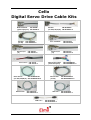
Cello
Digital Servo Drive Cable Kits
Main Feedback:
CBL-DFDBK
(general purpose) CBL-DFDBK-5
Encoder:
(for SE)
CBL-MTRENC4
CBL-MTRENC4-5
General I/O:
(J1)
CBL-CELIO1-5
CBL-CELIO1-5
Aux. Power:
CBL-CEL24-5
CBL-CEL24-5
Motor Power:
CBL-MTRPWR1CEL-5
(for SAR, SA,SB,SC) CBL-MTRPWR1CEL-5
RS-232 Com.:
-5
CBL-RJ452321
CBL-RJ452321-5
CAN Com.:
Encoder:
CBL-MTRENC2
(for SAR, SA,SB,SC) CBL-MTRENC2-5
Aux. Feedback:
CBL-CELAUX-5
CBL-CELAUX-5
General I/O:
(J2)
CBL-CELIO2-5
CBL-CELIO2-5
Motor Power Cable:
(General Purpose)
Motor Power:
(for SE)
CAN Com.:
CBL-RJ45CAN2-5
CBL-RJ45CAN2-5
CBL-MTRPWRCEL
CBL-MTRPWRCEL-5
CBL-MTRPWR2CEL-5
CBL-MTRPWR2CEL-5
CBL-RJ45CAN1-5
CBL-RJ45CAN1-5
Important Notice
This guide is delivered subject to the following conditions and restrictions:
This guide contains proprietary information belonging to Elmo Motion Control Ltd.
Such information is supplied solely for the purpose of assisting users of Elmo’s Cello
servo drives in assembling the required cables for their drive.
The text and graphics included in this manual are for the purpose of illustration and
reference only. The specifications on which they are based are subject to change
without notice.
Information in this document is subject to change without notice.
Doc. No. MAN-CBLKIT-CEL
Copyright ©2004
Elmo Motion Control Ltd.
All rights reserved.
Revision History
Document version 1.0: November 2004 (MAN-CBLKIT-CEL.pdf)
Elmo Motion Control Inc.
1 Park Drive, Suite 12
Westford, MA 01886
USA
Tel: +1 978 399-0034
Fax: +1 978 399-0035
[email protected]
Elmo Motion Control GmbH
Steinbeisstrasse 41
D-78056, Villingen-Schwenningen
Germany
Tel: +49 07720 8577-60
Fax: +49 07720 8577-70
[email protected]
www.elmomc.com
Cello Cable Kits
MAN-CBLKIT-CEL (Ver. 1.0)
Contents
1. Introduction ............................................................................................................................. 1
1.1 Cello Connectors.......................................................................................................................................... 1
1.2 Cable Cross-Reference................................................................................................................................ 2
2. Cable Kits ................................................................................................................................. 3
3. Main Feedback Cables ............................................................................................................ 4
3.1 Gen.-Purpose Main Feedback Cable (CBL-DFDBK-5)......................................................................... 4
3.2 Encoder Cable (CBL-MTRENC2-5 for SAR, SA, SB, SC)................................................................. 5
3.3 Encoder Cable (CBL-MTRENC4-5 for SE)........................................................................................... 6
4. Auxiliary Feedback Cable (CBL-CELAUX-5)....................................................................... 7
5. General I/O J1 (CBL-CELIO1-5) ............................................................................................ 8
6. General I/O J2 (CBL-CELIO2-5) ............................................................................................ 9
7. Auxiliary Power Cable (CBL-CEL24-5)................................................................................10
8. Motor Power Cables...............................................................................................................10
8.1 Motor Power Cable (CBL-MTRCEL-5)...............................................................................................10
8.2 Motor Power Cable (CBL-MTRPWR1CEL-5)...................................................................................11
8.3 Motor Power Cable (CBL-MTRPWR2CEL-5)...................................................................................11
9. Communication Cables .........................................................................................................12
9.1 RS-232 Option (CBL-RJ452321-5)..........................................................................................................12
9.2 CAN Option (CBL-RJ45CAN1-5).........................................................................................................13
9.3 CAN Option (CBL-RJ45CAN2).............................................................................................................14
Cello Cable Kits
1
MAN-CBLKIT-CEL (Ver. 1.0)
1. Introduction
This document provides the wiring details for the cables used to connect Cello digital
servo drives with the end-user application. The servo drive-side pinouts are provided in
Chapter 3 of the drive’s installation guide.
The cables come in two lengths: 2 meters (6 ½ feet) and 5 meters (16 ½ feet). The cable
length is indicated in the cable part number by use of an extended suffix to indicate 5
meter length. For example, cable CBL-CELAUX is a 2 meter cable while
CBL-CELAUX-5 is a 5 meter cable.
CBL-RJ45CAN2, is an exception, it is only 20 cm long.
1.1 Cello Connectors
The following connectors are used for wiring the Cello.
Type
Function
Port
5-pin
Pheonix (1st
two pins)
(provided)
Power
VP+, PR
5-pin
Pheonix
(last 3 pins)
(provided)
Motor
M1, M2,
M3
3 ground
screws
Ground
PE, PE,
PE
2-pin
Pheonix
(provided)
Optional
Back-up
Supply
24 VDC
Connector Location
Optional
Back-up Supply
Ground
Power & Motor
Table 1-1: The Cello’s Power Connectors
Type
Function
Port
15-pin DSub
Feedback A
Feedback A
15-pin DSub (highdensity)
General I/O
J1
15-pin DSub (highdensity)
General I/O
Connector Location
J2: I/O
J1: I/O
J2
Table 1-2: The Cello’s I/O and Feedback A Connectors
Feedback A
Cello Cable Kits
2
MAN-CBLKIT-CEL (Ver. 1.0)
Type
Function
Port
8-pin RJ-45
CANopen
CAN
8-pin RJ-45
CANopen
CAN
15-pin D-Sub
(high-density)
Feedback B
Feedback B
RS-232
RS-232
8-pin RJ-45
Connector Location
CANopen
Feedback B
RS-232
Table 1-3: The Cello’s Communications and Feedback B Connectors
1.2 Cable Cross-Reference
No. of
Label on
Cello
pg
Cable Application
Cable Part. No.
Main Feedback (gnrl-purpose)
CBL-DFDBK-5
15
Encoder (for SAR, SA, SB, SC)
CBL-MTRENC2-5
15
Encoder (for SE)
CBL-MTRENC4-5
15
Auxiliary Feedback
CBL-CELAUX-5
15
General I/O 1
CBL-CELIO1-5
15
J1
8
General I/O 2
CBL-CELIO2-5
15
J2
9
Auxiliary Power
CBL-CEL24-5
2
24v
10
Motor Power (gnrl-purpose)
CBL-MTRPWRCEL-5
4
Motor Power (for SAR, SA, SB, SC)
CBL-MTRPWR1CEL-5
4
Motor Power (for SE)
CBL-MTRPWR2CEL-5
4
RS-232 Communications
CBL-RJ452321-5
8
RS232
12
CAN Communications
CBL-RJ45CAN1-5
8
CAN
13
CAN Communications
CBL-RJ45CAN2-5
8
CAN
14
Pins
4
FEEDBACK A
5
6
FEEDBACK B
PE/M1
/M2/M3
7
10
11
11
Cello Cable Kits
3
MAN-CBLKIT-CEL (Ver. 1.0)
2. Cable Kits
Several Cable Kits can be purchased from Elmo. Each contain a set of 8 cables. The -5 suffix
on the kits and on the cables (CBL-DFDBK-5 for example) indicate that the cables are 5m
long. Cables and kits without that suffix are 2m long (except for CBL-RJ45CAN2 which is
20cm long). Customers may purchase cables in kits, or individually in multiples of 10
each. The contents of the kits are listed below:
Cable Application
Cable Part. No.
CBL-CELKIT01
-CELKIT01-5
CBL-CELKIT02
-CELKIT02-5
Main Feedback (gnrl-purpose)
CBL-DFDBK-5
1
–
Encoder (for SAR, SA, SB, SC)
CBL-MTRENC2-5
–
1
Encoder (for SE)
CBL-MTRENC4-5
–
-
Auxiliary Feedback
CBL-CELAUX-5
1
1
General I/O 1
CBL-CELIO1-5
1
1
General I/O 2
CBL- CELIO2-5
1
1
Auxiliary Power
CBL-CEL24-5
1
1
Motor Power (general-purpose)
CBL-MTRPWRCEL-5
1
-
Motor Power (SAR, SA, SB, SC)
CBL-MTRPWR1CEL-5
–
1
Motor Power (for SE)
CBL-MTRPWR2CEL-5
–
-
RS-232 Communications
CBL-RJ452321-5
1
1
CAN Communications
CBL-RJ45CAN1-5
1
1
CAN Communications
CBL-RJ45CAN2-5
-
-
Cello Cable Kits
4
MAN-CBLKIT-CEL (Ver. 1.0)
3. Main Feedback Cables
The main feedback cables are made of 24-AWG shielded cable. There are 3 types of feedback
cables, all use a 15-pin D-sub plug which connects to the FEEDBACK A port on the Cello.
•
The General-Purpose Main Feedback Cable (CBL-DFDBK) is open on the motor side
so that it can be connected to customer-specific connectors.
•
Encoder Cable CBL-MTRENC2 has a 15-pole socket on the motor side for Metronix
APM-SAR, SA, SB and SC motors.
•
Encoder Cable CBL-MTRENC4 has a 17-pole Amphenol socket on the motor side for
Metronix APM-SE motors.
3.1 Gen.-Purpose Main Feedback Cable (CBL-DFDBK-5)
Pin
No.
Color
1
Green
10
Yellow
2
Pink
3
White
4
Brown
5
Orange
6
Cyan
7
Blue
8
Red
9
–
11
–
12
–
13
–
14
Black
15
Purple
Pairs
pair
15 Pin
D-sub
Plug
pair
pair
pair
The specific
functionality of each pin
is fully outlined in the
Cello Installation Guide.
pair
Figure 1: Single-sided Main Feedback Cable (Part No. CBL-DFDBK-5)
Cello Cable Kits
5
MAN-CBLKIT-CEL (Ver. 1.0)
3.2 Encoder Cable (CBL-MTRENC2-5 for SAR, SA, SB, SC)
D-Type
Pin
No.
Color
Socket
Pin
No.
1
Green
11
HC
10
Yellow
9
HB
2
Pink
7
HA
Hall sensor A input
3
White
14
SUPRET
Supply return
4
Brown
13
+5V
5
Orange
2
CHA-
Signal
Pair
pair
pair
pair
6
Cyan
1
CHA
7
Blue
6
INDEX-
8
Red
5
INDEX
9
–
–
–
11
–
–
12
–
–
13
–
–
14
Black
4
Purple
3
pair
Hall sensor B input
15 Pin
D-sub
Plug
Encoder\Hall supply
+5 V
Channel A
complement
Index complement
Index
–
Pin No.5
Socket
Connector
Pin No.1
CHBCHB
Hall sensor C input
Channel A
pair
15
Description
Channel B
complement
Channel B
Figure 2: Encoder Cable (Part No. CBL-MTRENC2-5 for Metronix SAR, SA, SB, SC motors)
Cello Cable Kits
6
MAN-CBLKIT-CEL (Ver. 1.0)
3.3 Encoder Cable (CBL-MTRENC4-5 for SE)
D-Type
Pin
No.
Color
Socket
Pin
No.
1
Green
P
HC
Signal
Description
pair
Hall sensor C input
Yellow
M
HB
2
Pink
K
HA
Hall sensor A input
3
White
G
SUPRET
Supply return
4
Brown
H
+5V
5
Orange
B
CHA-
6
Cyan
A
CHA
Channel A
7
Blue
F
INDEX-
Index complement
8
Red
E
INDEX
9
–
–
–
–
11
–
–
–
–
12
–
–
–
–
13
–
–
–
–
14
Black
D
CHB-
Channel B
complement
15
Purple
C
CHB
Channel B
-
Drain
Wire
J
PE
Drain Wire
Connection
pair
10
Hall sensor B input
15 Pin
D-sub
Plug
Encoder\Hall supply
+5 V
pair
Channel A
complement
pair
Index
17 Pin
Amphenol
Socket
pair
Figure 3: Encoder Cable (Part No. CBL-MTRENC4-5 for Metronix SE motors)
Cello Cable Kits
7
MAN-CBLKIT-CEL (Ver. 1.0)
4. Auxiliary Feedback Cable (CBL-CELAUX-5)
The auxiliary feedback cable is a 24-AWG shielded cable. It is connected using an 15-pin
Hi-density D-sub plug which connects to the Cello’s FEEDBACK B port.
Four options — described in the Auxiliary Feedback section of the Cello Installation Guide
— are available for auxiliary feedback:
Main encoder buffered outputs
Differential encoder inputs
Single-ended encoder input
Pulse-and-direction input
The general pinout of the auxiliary feedback cable is as follows:
Port
Pin
Color
B1
1
Cyan
B1
B1
2
3
Orange
Purple
B1
4
Black
B1
B1
B2
B2
PWR
PWR
B2
B2
B2
B2
5
10
6
7
8
9
11
12
13
14
Red
Blue
Pink
Grey
Brown
White
Yellow
Green
White/Red
White/Black
PWR
15
White/Yellow
Pair
Description
pair
see Installation Guide
pair
see Installation Guide
pair
see Installation Guide
pair
see Installation Guide
pair
+5V
SUPRET
pair
see Installation Guide
pair
see Installation Guide
Pin Position
15 Pin high density
D-Sub Plug
The specific
functionality of
each pin is fully
outlined in the Cello
Installation Guide.
see Installation Guide
Figure 4: Auxiliary Feedback Cable (Part No. CBL-CELAUX-5)
Cello Cable Kits
8
MAN-CBLKIT-CEL (Ver. 1.0)
5. General I/O J1 (CBL-CELIO1-5)
The digital input cable is a 24-AWG shielded cable. It is connected using an 15-pin HiDensity D-sub socket.
Pin
Color
Signal
1
Orange
IN1
2
Cyan
IN2
3
Purple
IN3
8
Black
IN8
4
Gray
OUT2
5
Pink
OUT3
6
Blue
IN4
7
Red
IN7
9
White/
Yellow
INRET
General input return
10
White/
Red
OUTRET2-3
Programmable output
return 2 & 3
11
Yellow
OUT4
13
Green
OUT5
12
White/
Black
OUTRET4-5
14
Brown
OUT1
15
White
OUTRET 1
Pair
pair
pair
pair
pair
pair
Function
Programmable input 1
Programmable input 2
Programmable input 3
Pin Position
15 Pin
D-sub
Socket
Programmable input 8
Programmable output 2
Programmable output 3
Programmable input 4
Programmable input 7
Programmable output 4
Programmable output 5
Programmable output
return 4 & 5
Programmable output 1
pair
Programmable output
return 1
Figure 5: General Purpose I/O Cable (Part No. CBL-CELIO1-5)
Cello Cable Kits
9
MAN-CBLKIT-CEL (Ver. 1.0)
6. General I/O J2 (CBL-CELIO2-5)
The digital output cable is a 26-AWG shielded cable. It is connected using a 15-pin HiDensity D-sub plug.
Color
Signal
1
Orange
IN5
6
Cyan
INRET5
2
Purple
IN6
7
Black
INRET6
3
Blue
IN9
8
Red
INRET9
4
Pink
IN10
9
Gray
INRET10
5
Yellow
ANLIN1+
10
Green
ANLIN1-
11
Brown
ANLIN2+
12
White
ANLIN2-
13
White/
Black
ANLRET
14
White/
Red
ANLRET
Analog return
15
White/
Yellow
SUPRET
Supply return
Pin
Pair
pair
pair
pair
pair
pair
pair
Pin Position
Function
Programmable input 5
Programmable input return 5
Programmable input 6
Programmable input return 6
15 Pin
Hi-Density
D-sub
Plug
Programmable input 9
Programmable input return 9
Programmable input 10
Programmable input return 10
Analog input 1
Analog input 1
Analog input 2
Analog input 2
Analog return
pair
Figure 6: General Purpose I/O Cable (Part No CBL-CELIO2-5)
Cello Cable Kits
10
MAN-CBLKIT-CEL (Ver. 1.0)
7. Auxiliary Power Cable (CBL-CEL24-5)
The auxiliary power cable is a 24-AWG shielded cable terminated by pins on the SimplIQ
side. The pins are screwed into the 2-pole Pheonix Terminal Block provided with the Cello.
Pin
No.
Color
1
Red
2
Black
Twisted &
Shielded
Wire
Signal
Pair
Description
+24VDC
+24 VDC auxiliary power supply
RET24VDC
Return (common) of 24 VDC auxiliary power supply
Figure 7: Auxiliary Power Cable (Part No. CBL-CEL24-5)
8. Motor Power Cables
There are three types of power cables:
8.1
Motor Power Cable (CBL-MTRPWRCEL-5)
CBL-MTRPWRCEL is a general-purpose motor power cable. It is made from four 14-AWG
shielded wires with pin terminals on the Cello drive. The pins are connected to the
Pheonix Terminal Block supplied with the Cello. The other end is open so that it can be
attached to a customer-specific connector.
Color
Signal
Description
White
M1
Motor Phase 1 (U)
Black
M2
Motor Phase 2 (V)
Red
M3
Motor Phase 3 (W)
Green
PE
Ground
Figure 8: General-Purpose Motor Power Cable (Part No. CBL-MTRPWRCEL-5)
Cello Cable Kits
11
MAN-CBLKIT-CEL (Ver. 1.0)
8.2
Motor Power Cable (CBL-MTRPWR1CEL-5)
CBL-MTRPWR1CEL-5 is a 24-AWG shielded cable in which each wire, on the SimplIQ
drive side, is connected to a pin terminal and the wires on the motor side are connected to
a 4-pole socket. This cable is designed for connecting a Cello to a Metronix APM-SAR, SA,
SB or SC motor.
Color
Signal
Drive Side
Description
AMP Pin No.
Motor Side
Brown & White
M1
Motor Phase 1 (U)
1
Pink & Grey
M2
Motor Phase 2 (V)
2
Blue & Red
M3
Motor Phase 3 (W)
3
Green & Yellow
PE
Ground
4
Figure 9: SAR, SA, SB, SC-type Motor Power Cable (Part No. CBL-MTRPWR1CEL-5)
8.3
Motor Power Cable (CBL-MTRPWR2CEL-5)
CBL-MTRPWR2CEL is designed to provide power to Metronix SE motors. It is made from
four 14-AWG shielded wires with pin terminals on the Cello side. The other end has an
Amphenol 4-pole socket so that it can be attached to an Amphenol plug on the motor.
Amphenol
Pin No.
Motor Side
Color
Signal
Drive Side
White
M1
Motor Phase 1 (U)
A
Black
M2
Motor Phase 2 (V)
B
Red
M3
Motor Phase 3 (W)
C
Green
PE
Ground
D
Description
Figure 10: SE-type Motor Power Cable (Part No. CBL-MTRPWR2CEL-5)
Cello Cable Kits
12
MAN-CBLKIT-CEL (Ver. 1.0)
9. Communication Cables
The communication cables use 26-AWG twisted pair shielded cable. They are connected
using an 8-pin RJ-45 plug. Elmo drives can communicate using the following options:
RS-232, full duplex
CANopen
9.1 RS-232 Option (CBL-RJ452321-5)
Color
D-type
Female
Pin No.
Signal
3
Brown
2
Tx
RS-232 transmit
5
White
5
COMRET
Communication
return
6
Green
3
Rx
body
Drain
Wire
body
shield
RJ45
Pin
No.
Description
RS-232 receive
cable shield
1
The shields of the RJ-45 and D-type plugs are connected to each other through the
cable braid.
Figure 11: RS-232 Communications Cable (Part No. CBL-RJ452321-5)
Cello Cable Kits
13
MAN-CBLKIT-CEL (Ver. 1.0)
9.2 CAN Option (CBL-RJ45CAN1-5)
Color
D-type
Female
Pin No.
Signal
Description
1
Green
7
CAN-H
CAN_H bus line
2
Yellow
2
CAN_L
CAN_L bus line
3
White
3
CAN_GND
CAN ground
4
—
—
—
—
5
—
—
—
—
7
—
—
—
—
8
—
—
—
—
body
Drain
Wire
body
shield
RJ45
Pin
No.
1
cable shield
The shields of the RJ-45 and D-type plugs are connected to each other through the
cable braid.
Figure 12: CAN Cable (Part No. CBL-RJ45CAN1-5)
Cello Cable Kits
14
MAN-CBLKIT-CEL (Ver. 1.0)
9.3 CAN Option (CBL-RJ45CAN2)
Cable CBL-RJ45CAN2 is 20 cm long, it is used for “daisy-chaining” CAN nodes. On the
Harmonica this cable is connected to the External Dual Can Port.
Color
RJ45
Pin
No.
Signal
Description
1
Green
1
CAN-H
CAN_H bus line
2
Yellow
2
CAN_L
CAN_L bus line
3
White
3
CAN_GND
CAN ground
4
—
—
—
—
5
—
—
—
—
7
—
—
—
—
8
—
—
—
—
body
Drain
Wire
body
shield
cable shield
RJ45
Pin
No.
1
The shields of the two RJ-45 plugs are connected to each other through the cable
braid.
Figure 13: CAN Cable (Part No. CBL-RJ45CAN2)