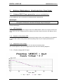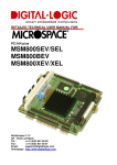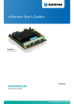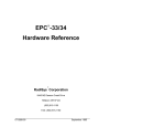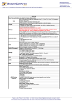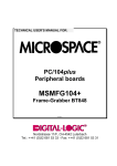
1
TECHNICAL USER'S MANUAL FOR: PC/104 Peripheral boards MSMVGA 65545 based VGA/LCD controller #260399-1 Nordstrasse 11/F, CH-4542 Luterbach Tel.: ++41 (0)32 681 53 33 - Fax: ++41 (0)32 681 53 31 DIGITAL-LOGIC AG MSMVGA Manual V1.0 COPYRIGHT 1998-1999 BY DIGITAL-LOGIC AG No part of this document may be reproduced, transmitted, transcribed, stored in a retrieval system, in any form or by any means, electronic, mechanical, optical, manual, or otherwise, without the prior written permission of DIGITAL-LOGIC AG. The software described herein, together with this document, are furnished under a license agreement and may be used or copied only in accordance with the terms of that agreement. REVISION HISTORY: Prod.-Serialnumber: From: To: Product Version V1.0 V1.0 Document Version V0.1b V0.2 V1.0 Date/Vis: Modification: Remarks, News, Attention: 01.99 JM Initial Version 02.99 JM Jumper Location 03.99 JM Released Version Registration Form: Please register your product under: http://www.digitallogic.ch -> SUPPORT -> Product Registration After registration, you will receive driver & software updates, errata information, customer information and news from DIGITAL-LOGIC AG products automatically. 2 DIGITAL-LOGIC AG MSMVGA Manual V1.0 Table of Contents 1 1.1 1.2 1.3 1.4 1.5 1.6 1.7 PREFACE ...............................................................................................................4 How to use this Manual ........................................................................................... 4 Trademarks............................................................................................................. 4 Disclaimer ............................................................................................................... 4 Who should use this product ................................................................................... 4 Recycling Information.............................................................................................. 5 Technical Support ................................................................................................... 5 Limited Warranty ..................................................................................................... 5 2 MSMVGA SPECIFICATIONS ....................................................................................6 3 VGA, LCD............................................................................................................7 3.1 3.2 4 4.1 5 5.1 5.2 6 VGA / LCD Controller 65540/45 .............................................................................. 7 VGA/LCD BIOS Support ....................................................................................... 10 SOFTWARE ..........................................................................................................10 Available Drivers ................................................................................................... 10 Description of the Connectors .......................................................................11 VGA-Connector Analog Interface for Monitors ...................................................... 11 VGA Connector for Flatpanel Display.................................................................... 12 JUMPER LOCATION ON THE BOARD........................................................................13 6.1 The Jumpers on this MICROSPACE product ........................................................ 13 6.1.1 Flatpanel Interface .......................................................................................... 13 6.1.2 Standby the VGA Controller:........................................................................... 13 6.1.3 Selection of the BIOS Address........................................................................ 13 6.1.4 16-Bit CPU Interface: ...................................................................................... 13 6.1.5 Selection of the Flash Sector .......................................................................... 14 6.1.6 VEE Generator supply .................................................................................... 14 6.1.7 Enable VEE Output at the J4 .......................................................................... 14 6.2 Jumper Locations .................................................................................................. 15 7 SPECIAL PERIPHERALS, CONFIGURATION, FUNCTIONS............................................16 7.1 Onboard BIAS Power generation (only on the MSMV104L) ................................. 16 7.1.1 VEE Generation.............................................................................................. 16 7.1.2 Selection of the polarity VEE........................................................................... 16 7.1.3 Adjustment of the voltage ............................................................................... 16 7.1.3.1 Positive voltage with 5V input ...................................................................... 16 7.1.3.2 Negative voltage with 5V input..................................................................... 17 8 8.1 8.2 9 POSSIBLE FAILURES .............................................................................................18 General LCD Failures............................................................................................ 18 The LCD is not stable............................................................................................ 18 INDEX ..................................................................................................................19 3 DIGITAL-LOGIC AG 1 MSMVGA Manual V1.0 PREFACE This manual is for integrators and programmers of systems based on the MICROSPACE card family. It contains information on hardware requirements, interconnections, and details of how to program the system. The specifications given in this manual were correct at the time of printing; advances mean that some may have changed in the meantime. If errors are found, please notify DIGITAL-LOGIC AG at the address shown on the title page of this document, and we will correct them as soon as possible. 1.1 How to use this Manual This manual is written for the original equipment manufacturer (OEM) who plans to build computer systems based on the single board MICROSPACE-PC. It provides instructions for installing and configuring the MSMVGA board, and describes the system and setup requirements. 1.2 Trademarks Chips & Technologies SuperState R MICROSPACE, MicroModule DIGITAL-LOGIC AG DOS Vx.y, Windows Microsoft Inc. PC-AT, PC-XT IBM NetWare Novell Corporation Ethernet Xerox Corporation DR-DOS, PALMDOS Digital Research Inc. / Novell Inc. ROM-DOS Datalight Inc. 1.3 Disclaimer DIGITAL-LOGIC AG makes no representations or warranties with respect to the content of this manual and specifically disclaims any implied warranty of merchantability or fitness for any particular purpose. DIGITAL-LOGIC AG shall under no circumstances be liable for incidental or consequential damages or related expenses resulting from the use of this product, even if it has been notified of the possibility of such damage. DIGITAL-LOGIC AG reserves the right to revise this publication from time to time without obligation to notify any person of such revisions. If errors are found, please contact DIGITAL-LOGIC AG at the address listed on the title page of this document. 1.4 - Who should use this product Electronic engineers with know-how in PC-technology. Without electronic know-how we expect you to have questions. This manual assumes, that you have a general knowledge of PC-electronics. Because of the complexity and the variability of PC-technology, we can’t give any warranty that the product will work in any particular situation or combination. Our technical support wil help you. Pay attention to the electrostatic discharges. Use a CMOS protected workplace. Power supply OFF when you are working on the board or connecting any cables or devices. This is a high-technology product. You need know-how in electronics and PC-technology to install the system ! 4 DIGITAL-LOGIC AG 1.5 Recycling Information Hardware: - Print: Software: 1.6 MSMVGA Manual V1.0 epoxy with glass fiber wires are of tin-plated copper - Components: ceramics and alloys of gold, silver check your local electronic recycling - no problems: re-use the diskette after formatting Technical Support 1. Contact your local Digital-Logic Technical Support in your country. 2. Use Internet Support Request form on http://www.digitallogic.ch -> support 3. Send a FAX or an E-mail to DIGITAL-LOGIC AG with a description of your problem. DIGITAL-LOGIC AG Technical Support Dept. Nordstrasse 11/F CH-4542 Luterbach (SWITZERLAND) Fax: ++41-32 681 53 31 E-Mail: [email protected] Support requests will only be accepted with detailed informations about the product (BIOS, Board Version) ! 1.7 Limited Warranty DIGITAL-LOGIC AG warrants the hardware and software products it manufactures and produces to be free from defects in materials and workmanship for one year following the date of shipment from DIGITAL-LOGIC AG, Switzerland. This warranty is limited to the original product purchaser and is not trans-ferable. During the one year warranty period, DIGITAL-LOGIC AG will repair or replace, at its discretion, any defective product or part at no additional charge, provided that the product is returned, shipping prepaid, to DIGITAL-LOGIC AG. All replaced parts and products become property of DIGITAL-LOGIC AG. Before returning any product for repair, customers are required to contact the company. This limited warranty does not extend to any product which has been damaged as a result of accident, misuse, abuse (such as use of incorrect input voltages, wrong cabling, wrong polarity, improper or insufficient ventilation, failure to follow the operating instructions that are provided by DIGITAL-LOGIC AG or other contingencies beyond the control of DIGITAL-LOGIC AG), wrong connection, wrong information or as a result of service or modification by anyone other than DIGITALLOGIC AG. Neither, if the user has not enough knowledge of these technologies or has not consulted the product manual or the technical support of DIGITAL-LOGIC AG and therefore the product has been damaged. Except, as expressly set forth above, no other warranties are expressed or implied, including, but not limited to, any implied warranty of merchantability and fitness for a particular purpose, and DIGITALLOGIC AG expressly disclaims all warranties not stated herein. Under no circumstances will DIGITAL-LOGIC AG be liable to the purchaser or any user for any damage, including any incidental or consequential damage, expenses, lost profits, lost savings, or other damages arising out of the use or inability to use the product. 5 DIGITAL-LOGIC AG 2 MSMVGA Manual V1.0 MSMVGA SPECIFICATIONS Controller: Enhanced BIOS: Default Panels: Memory: 65545 from C&T VGA / LCD BIOS MultiBios Feature 1. CRT and MONO-LCD 2. CRT and TFT LCD Type Sharp Mono LM64P8XX Type Sharp TFT LQD011 and Toshiba TFT LTM9C015 3. CRT and STN-Color LCD Type Torisan STN Color LMCA53/22NAZ 4. CRT and EL-Plasma Type Sharp TFT LQ10DH11 DRAM onboard: 1 MByte CRT-Monitor: Resolution: Flatpanel-Display: VGA / SVGA up to 768 x 1024 Pixel 64k Colors TFT: 640 x 480 , 800 x 600, 1024 x 768 with 8,9,12,15,16,18 Bits STN: 640 x 480 , 800 x 600, 1024 x 768 Monochrome STN: 640 x 480 with 64 colors 2-2/3 and 5-1/3 bit DD and SS Plasma:640 x 480 to 1280 x 1024 EL: 640 x 350 , 640 x 480, 768 x 1024 Pixels Connectivity: CRT only Flatpanel only CRT and Flatpanel (Default) simultaneous Contrast Control: Backlight Control: Frame Buffer: Supported Standard Panels with MultiBIOS: 10kOhm software controlled resistor with 100 steps 10kOhm software controlled resistor with 100 steps 64k advanced frame buffer architecture CRT simultaneous with: 1. MONO STN 2. TFT - FP 3. STN-Color FP 4. EL Panel see also Flatpanel Support Manual by DIGITAL-LOGIC AG; list with already adapted flatpanels Standard: PC/104 Size: 16 Bit only Power Normal: 5V/260mA Power Suspend: 5V/200mA Power Sequencing: control by 65545 for VCC, Bias, Backlight Bias Voltage: -30 to +30 Volt, 40mA Dimension: Length: 96 mm Width: 90 mm Height: 20 mm 5 - 90 % non condensing Relative humidity: Vibration: 5 to 2000 Hz Shock: 10 g Temperature: Operating: -25°C to +70°C Extended: -25°C to +85°C Bus: Power Supply: Physical Characteristics: Operating Environment: Ordering Information: MSMVGAL MSMVGA PC/104 VGA Board with VEE Voltage generation PC/104 VGA Board without VEE-Voltage generation (CRT and TFTs) Any information is subject to change without notice. 6 DIGITAL-LOGIC AG 3 MSMVGA Manual V1.0 VGA, LCD 3.1 VGA / LCD Controller 65540/45 The 65540 High Performance Flatpanel/CRT VGA controller • High integrated design (flatpanel/CRT VGA controller, RAMDAC, clock synthesizer) • Local Bus (32 Bit CPU) • Flexible display memory configurations – Two 256Kx16 DRAM (1024 KB) • Advanced frame buffer architecture uses available display memory, maximizing integration and minimizing chip count • Integrated programmable linear address feature accelerates GUI performance • Hardware windows acceleration (65545) - 32-Bit graphics engine - System-to-screen and screen-to-screen BitBlt - 3 operand ROPs - Color expansion - Optimized for Windowsä BitBlt format - Hardware line drawing - 64x64x2 hardware cursor • Hardware pop-up icon (65545) - 64x64 pixels by 4 colors - 128x128 pixels by 2 colors • High performance resulting from zero wait-state writes (write buffer) and minimum wait-state reads (internal asynchronous FIFO design) • Mixed 3.3 V / 5.0 V +/- 10 % Operation • Supports panel resolutions up to 1280 x 1024, including 800x600 and 1024x768 • Supports non-interlaced CRT monitors with resolutions up to 1024 x 768 / 256 colors • True-color and Hi-color display capability with flatpanels and CRT monitors up to 640x480 resolution • Direct interface to Color and Monochrome Dual Drive (DD) and Single Drive (SS) panels (supports 8, 9, 12, 15, 16, 18 and 24-Bit data interfaces) • Advanced power management features minimize power consumption during: - Normal operation - Standby (Sleep) modes - Panel-Off Power-Saving Mode • Flexible onboard Activity Timer facilitates ordered shut-down of the display system • Power Sequencing control outputs regulate application of Bias voltage, +5 V to the panel and +12 V to the inverter for backlight operation • SMARTMAPä intelligent color to gray scale conversion enhances text legibility • Text enhancement feature improves white text contrast on flatpanel displays • Fully Compatible with IBMä VGA 7 DIGITAL-LOGIC AG MSMVGA Manual V1.0 65545 Display Capabilities CRT Mode Resolution 320x200 640x480 640x480 800x600 800x600 1024x768 1024x768 1280x1024 4 Color 256 /256K 16 / 256K 256 / 256K 16 / 256K 256 / 256K 16 / 256K 256 / 256K 16 / 256K Mono LCD 4 Gray Scales 61 / 61 16 / 61 61 / 61 16 / 61 61 / 61 16 / 61 61 / 61 16 / 61 DD STN LCD 2, 3, 4 Colors 256 / 226,981 16 / 226,981 256 / 226,981 16 / 226,981 256 / 226,981 16 / 226,981 256 / 226,981 n/a 9-Bit TFT LCD 1, 2, 3, 4 Colors 256 / 185,193 16 / 185,193 256 / 185,193 16 / 185,193 256 / 185,193 16 / 185,193 256 / 185,193 n/a Video Memory 512 KB 512 KB 512 KB 512 KB 512 KB 512 KB 1 MB 1 MB Simultaneous Display yes yes yes yes with 1 MB yes with 1 MB yes with 1 MB yes n/a Notes: 1 2 3 4 Larger color palettes and simultaneous colors can be displayed on 12-Bit, 18-Bit, and 24-Bit TFT panels via the 65540/545 video input port. Includes dithering. Includes frame rate control. Colors are described as number of simultaneous on-screen colors and number of unique colors available in the color palette. 256K colors assumes DAC output mode is set to 6 bits of R, G & B. If DAC is set to 8-Bit output mode, the number of available colors is 16 M. VGA Controller Chips C&T 65545 32bit local bus up 1024kRAM hardware accelerator CRT Displays The 65545A supports resolution fixed frequency and variable frequency analog monitors in interlaced and non-interlaced modes of operation. Digital monitor support is also built in. 8 DIGITAL-LOGIC AG MSMVGA Manual V1.0 Supported VGA Modes Mode: 0,1 2,3 4,5 6 7+ D E F 10 11 12/12+ 13 20 22 30 32 60 61 72 79 7C Type: Text Text Graphic Graphic Text Planar Planar Planar Planar Planar Planar Planar 4 Bit Lin 4 Bit Lin 8 Bit Lin 8 Bit Lin Text Text Planar Packed Packed Colors: 16 16 4 2 Mono 16 16 Mono 16 2 16 256 16 16 256 256 16 16 16 256 256 CRT: ABC ABC ABC ABC ABC ABC ABC ABC ABC ABC ABC/BC ABC ABC BC ABC BC ABC ABC C ABC BC Text: 40 x 25 80 x 25 40 x 25 80 x 25 80 x 25 40 x 25 80 x 25 80 x 25 80 x 25 80 x 30 80 x 30 40 x 25 80 x 30 100 x 37 80 x 30 100 x 37 132 x 25 132 x 50 128 x 48 80 x 30 100 x 37 Graphic: 320 x 200 640 x 200 320 x 200 640 x 200 720 x 350 320 x 200 640 x 200 640 x 350 640 x 350 640 x 480 640 x 480 320 x 200 640 x 480 800 x 600 640 x 480 800 x 600 1056 x 400 1056 x 400 1024 x 768 640 x 480 800 x 600 DRAM: 256k 256k 256k 256k 256k 256k 256k 256k 256k 256k 256k 256k 512k 512k 512k 512k 256k 256k 512k 512k 512k Monitor: CGA CGA CGA CGA HGC CGA CGA EGA EGA VGA VGA CGA VGA SVGA VGA SVGA MGA MGA HVGA VGA SVGA Refresh/HR: 70 Hz 70 Hz 70 Hz 70 Hz 70 Hz 70 Hz 70 Hz 70 Hz 70 Hz 60 Hz 60 Hz/72Hz 70 Hz (not 8 Bit Bus) 60 Hz 60 Hz 60 Hz/72 Hz 60 Hz/72 Hz 68 Hz 68 Hz 60 Hz 72 Hz 72 Hz HiVGA HiVGA HiVGA HiVGA VGA VGA HiVGA 60 Hz 43 Hz 60 Hz 43 Hz 60 Hz 60 Hz 60 Hz supported on MSM486DX boards version 4.0 with 1Mbyte videoram. 24 26 34 36 40 41 7E 4 Bit Lin 4 Bit Lin 8 Bit Lin 8 Bit Lin 15 Bit Lin 16 Bit Lin Packed 16 16 256 256 32k 64k 256 C BC C BC ABC ABC C 128 x 48 128 x 48 128 x 48 128 x 48 80 x 30 80 x 30 128 x 48 1024 x 768 1024 x 768 1024 x 768 1024 x 768 640 x 480 640 x 480 1024 x 768 1024k 1024k 1024k 1024k 1024k 1024k 1024k A = PS/2 fixed frequency analog monitor; B = Multifrequency CRT monitor like NEC Multisynch 3D or eq. C = Nanao/EIZO 9070, NEC Multisynch 5D, or eq. Simultaneous Flatpanel / CRT Display The 65540/45 provides simultaneous display operation with Multi-Sync variable frequency or PS/2 fixed frequency CRT monitors and single panel-single drive LCDs (LCD-SS), dual panel-single drive LCDs (LCD-DS), dual panel-dual drive LCDs (LCD-DD) and plasma and EL panels (which contains single panel-single drive interfaces). Single drive panels sequence data in the same manner as CRTs so the 65540/45 provides simultaneous display with CRTs and LCD-SS, LCD-DS, plasma or EL panels by driving the panels with CRT timing. No external hardware is required. In contrast, LCD-DD panels require video data alternating between separate locations in the memory. In addition, a dualdrive panel requires data from both locations simultaneously. The 65540/45 also provides simultaneous display with LCD-DD and CRT monitors without using external VRAMs. The internal VRAM frame buffers offer significant advantages relative to competitors' DRAM frame buffers. A DRAM frame accelerator requires that the flatpanel is refreshed at double of the CRTs vertical refresh rate. Therefore, an expensive 6.3 MHz LCD (with 120 Hz panel vertical refresh rate) is required for simultaneous display with 60 Hz CRT monitors when a DRAM frame buffer is used. Due to its higher bandwidth relative to DRAMS, a VRAM frame buffer can refresh both the flatpanel and CRT at the same vertical refresh rate. Therefore, inexpensive 3 MHz and 6 MHz LCDs (in addition to 6.3 MHz LCDs) can be used for simultaneous display with 60 Hz and 72 Hz CRT monitors when a VRAM frame buffer is used. 9 DIGITAL-LOGIC AG MSMVGA Manual V1.0 Simultaneous Display CRT: + Flatpanel type: Needed modifications: CRT CRT CRT CRT CRT + + + + + Mono Single Drive STN LCD Mono Dual Drive STN LCD Mono Single Drive TFT LCD Color Single Drive STN LCD Color Single Drive TFT LCD none none none none none 3.2 VGA/LCD BIOS Support Each LCD display needs a specific adapted VGA-BIOS. Standard this product is equiped with the CRT standard VGABIOS. To connect a LCD Display to this product, you need to perform the following: 1. Check the FP_LIST.PDF if the LCD BIOS is available. Get the latest VGA-BIOS at our webpage http://www.digitallogic.ch 4 SOFTWARE 4.1 Available Drivers he MICROSPACE Application CD contains a lot of various drivers. CD:\drivers\display\vga45\ dos nt4 w95_vl win311 win311_vl win95 Drivers for DOS Windows NT4.0 Windows 95 VESA Windows 3.11 Windows 3.11 VESA Windows 95 10 DIGITAL-LOGIC AG MSMVGA Manual V1.0 5 Description of the Connectors 5.1 VGA-Connector Analog Interface for Monitors Signal Name VGA-Connector Sub-D 15 pol VGA red VGA green VGA blue Horizontal Sync. Vertical Sync. Ground Bridge MICROSPACE Product MSMVGA/L Pin No. 1 2 3 13 14 7 8 + 11 Header Pin No. 32 34 36 38 39 31 11 DIGITAL-LOGIC AG 5.2 J4 MSMVGA Manual V1.0 VGA Connector for Flatpanel Display LCD Connector VGA-LCD Interface (flatpanel signals): Signals P20-P23 are located on the J4M connector Pin Signal Pin Signal 1 3 5 7 9 11 13 15 17 19 21 23 25 27 29 M-Signal (altern. DE) P18 VCC Switched VDD (5V/1A) Switched B’light (12V/1A) P2 P1 P0 Enable VEE (TTL) VCC Panel (5V/3,3V) P4 P8 P10 P12 P14 2 4 6 8 10 12 14 16 18 20 22 24 26 28 30 FLM Line Pulse LP GND Shift Clock P3 P17 P16 P7 P6 P5 P19 P9 P11 P13 P15 The Pin 9 is supplied from (+12V) . J4 VGA Monitor (CRT-Signals) J4 Header 40 Pin Signal 15 pins HiDensity DSUB Pin Signal Pin 32 Pin 34 Pin 36 Pin 38 Pin 39 VGA red VGA green VGA blue Horizontal Synch Vertical Synch Pin 31 Ground Pin 1 Pin 2 Pin 3 Pin 13 Pin 14 Pin 8 + 11 Pin 7 Pin 5 Pin 33 Pin 35 Pin 37 Pin 40 LCD-P20 LCD-P21 LCD-P22 LCD-P23 or VEE * Red Green Blue H-Synch V-Synch Bridge Ground not connected The VGA-CRT signals from J4 must be wired to a standard VGA HiDensity DSub connector (female): *) Pin40 function is selected by the J27. Solderside view of the female 15pin HiDSub 1 6 2 3 4 Red Green Blue 7 8 9 5 GND 10 GND 11 12 13 14 15 Hsyn VSyn 12 DIGITAL-LOGIC AG MSMVGA Manual V1.0 6 JUMPER LOCATION ON THE BOARD 6.1 The Jumpers on this MICROSPACE product 6.1.1 Flatpanel Interface Flatpanel Interface: J6 1-2 negative -35V Flatpanel Interface: VEE-Polarity 2-3 positive +35V 6.1.2 Standby the VGA Controller: Standby the VGA Controller: J9 (smd jumper) 1-2 Standby the VGA Controller: StnBY active (Default) 2-3 Standby 6.1.3 Selection of the BIOS Address J10 Function: Selection of the BIOS Address FLASH Boot process: Flash Operation Jumper Position, Address: 1-2 = C000 Jumper Position, Address: 2-3 = C800 6.1.4 16-Bit CPU Interface: 16-Bit CPU Interface: Default-16 Bit: J13 (smd jumper) SMEMR-MEMR J14 (smd jumper) SMEMW-MEMW closed = not used open = 16Bit closed = not used open = 16Bit 13 DIGITAL-LOGIC AG MSMVGA Manual V1.0 6.1.5 Selection of the Flash Sector (for using C800-CFFF, as alternate Flash-BIOS Memory, use the 64k-GAL. The standard implementation is 32k-GAL!) J18, J19 Selected Sector: J18 J19 Sector 1 (Default) Sector 2 Sector 3 Sector 4 open closed open closed open open closed closed 6.1.6 VEE Generator supply If there is an external 12V power supply at the PC/104 BUS PIN B9, switch the Jumpers J25 and J26 to 2-3. With 12V at the VEE generator the stability of the VEE range is improved. VEE Range -35V to +35V. Jumper J25 J26 • Function VEE Generator supply VEE Generator supply PIN 1-2 = 5V * 1-2 = 5V * PIN 2-3 = 12V 2-3 = 12V Default 6.1.7 Enable VEE Output at the J4 Pin 40 is selectable to output VEE supply or the P23 ATTENTION: Select never the J27 to VEE-Output if a LCD is connected with the digital P23 signal on the Pin 40 of the J4 (LCD-Outputconnector) ! The LCD will be destroyed immediately with the overvoltage of the VEE generator ! Jumper J8 J28 J29 Function N/A N/A N/A 14 DIGITAL-LOGIC AG Jumper Locations R72 J27 J6 1 1 J26 1 J18 1 U14 J19 1 J25 J10 U13 J28 1 DIGITAL-LOGIC AG MSMVGA V1.0 JMP-LOCATION TOP-SIDE 0299 JM 1 J9 J29 1 1 J8 J14 J13 15 J4 - VGA/LCD CONNECTOR 6.2 MSMVGA Manual V1.0 DIGITAL-LOGIC AG MSMVGA Manual V1.0 7 SPECIAL PERIPHERALS, CONFIGURATION, FUNCTIONS 7.1 Onboard BIAS Power generation (only on the MSMV104L) On the MSMV104L (low cost) board is no BIAS generator implemented. IMPORTANT: The onboard voltage generation must be adjusted and measured before the LCD panel is connected, otherwise the display may be destroyed. Follow these steps: 7.1.1 VEE Generation If there is an external 12V power supply at the PC/104 BUS PIN B9, switch the Jumpers J25 and J26 to 2-3. With 12V at the VEE generator the stability of the VEE range is improved. VEE Range -35V to +35V. 7.1.2 Selection of the polarity VEE Some displays use positive, other use negative BIAS voltages. Refer to the datasheet of the flatpanel in order to find out the correct polarity. With the polarity jumper J6 (see Jumper) the definition is made. 7.1.3 Adjustment of the voltage The voltage may be varied between 35V and 15V with the selected polarity. The current depends on the input voltage and the load. Check the following diagrams: 7.1.3.1 Positive voltage with 5V input 16 DIGITAL-LOGIC AG MSMVGA Manual V1.0 7.1.3.2 Negative voltage with 5V input 17 DIGITAL-LOGIC AG 8 POSSIBLE FAILURES 8.1 General LCD Failures MSMVGA Manual V1.0 Refer to the Flatpanel Manual by DIGITAL-LOGIC AG. 1. Check the LCD-BIOS. You have a special BIOS for every LCD. 2. Check the cable to the LCD. 3. Check the Jumper. 4. Check the power supply. 8.2 The LCD is not stable Try to place a resistor at the VEE to the GND. VEE MSMV LCD 10K-22K This occurs to LCDs which do not consume enough current. Try to raise the resistor values as much as possible. 18 DIGITAL-LOGIC AG 9 MSMVGA Manual V1.0 INDEX 1 N 16-Bit CPU Interface:........................................... 14 Negative voltage with 5V input ............................ 18 C P CRT Displays ......................................................... 9 Positive voltage with 5V input .............................. 17 F S Failures ................................................................ 19 Flash-BIOS Memory, ........................................... 15 J Selection of the BIOS Address ............................ 14 Selection of the Flash Sector............................... 15 Selection of the polarity VEE ............................... 17 Simultaneous display........................................... 11 Standby the VGA Controller ................................ 14 Jumper Locations ................................................ 16 jumpers ................................................................ 14 V VEE Generation................................................... 17 VEE Generator supply ......................................... 15 VEE-Polarity ........................................................ 14 VGA ....................................................................... 8 VGA Controller Chips ............................................ 9 VGA Modes ......................................................... 10 VGA Monitor ........................................................ 13 VGA-Connector Analog Interface for Monitors .... 12 L LCD Connector .................................................... 13 LCD Controller ....................................................... 8 LCD is not stable ................................................. 19 19