1
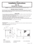
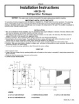
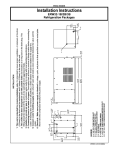
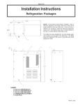
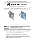
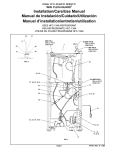
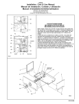
NOTICE: This water cooler must be connected to the water supply using a dielectric coupling. INSTALLATION ERW32-1C A = 3/8" O.D. TUBE WATER INLET B = 3/8" O.D. TUBE WATER OUT C = TEMPERATURE ADJUSTMENT D = ELECTRICAL E = 3/8" O.D. TUBE TANK DRAIN F = 3/8" O.D. TUBE CONDENSER WATER OUTLET G = 3/8" O.D. TUBE CONDENSER WATER INLET H = FREEZE CONTROL Installation Instructions 97657C (REV. G - 8/03) LEGEND ERW32-1C Refrigeration Packages 1. This unit is intended for remote installation only. It is important to insure proper ventilation. A minimum of 6 inches (152mm) to the front must be maintained, and 6 inches (152mm) to the rear of the unit. 2. This chiller has been designed for use with potable water and includes an o-ring seal on the drain plug. This fitting should be replaced if the unit is to be used with more aggressive fluids. 3. Installer to provide air gap at condenser water outlet to comply with local plumbing specifications. 4. Connecting lines to be made of copper. Thoroughly flush all lines to remove all foreign matter before connecting to cooler. If flushing does not remove all particles, a water strainer should be installed in the supply line. 5. Connect cooler to building supply with a shut-off valve and install a union connection between the valve and the cooler. 6. Electrical: Make sure power supply is identical in voltage, cycle, and phase to that specified on cooler serial plate. Never wire the compressor directly to the power supply. ERW32-1C PARTS LIST ITEM NO. PART NO. 1 2 3 4 5 6 7 8 9 10 11 *12 13 14 15 16 18 19 20 21 22 23 24 25 26 27 28 29 30 28165C 28218C 28166C 28032C 23158C 26701C 34783005 35882C 66633C 36034C 30768C 35985C 35984C 35989C 35988C 35990C 30039C 50196C 66624C 70772C 66621C 70020C 66623C 30040C 36045C 70482C 70274C 70483C 35895C START-UP DESCRIPTION 1. Open supply line valve. 2. Purge all air from all water lines by operating bubbler valve of fountain to which cooler is connected. A steady stream flow assures that all air is removed. 3. Rotate fan blade to assure proper clearance and free action. 4. Connect to proper electrical power. BOX - INSULATION BASE ASSY PANEL PANEL - FRONT/REAR COVER - INSULATION BOX CABINET WASHER - LOCK CONTROL - COLD CONDENSER ASSY CSIR BOX ASSY SOLENOID VALVE COMPRESSOR SERVICE PAK OVERLOAD GASKET - TERM COVER OVERLOAD SPRING BALE STRAP ELECTRICAL BOX GROMMET - COMPRESSOR MTG EVAPORATOR ASSY EVAPORATOR DRAIN PLUG DRIER NUT HEAT EXCHANGER ELECTRICAL BOX COVER OVERLOAD COVER MALE CONNECTOR FITTING SLEEVE-COMPRESSOR ELBOW FITTING FREEZE CONTROL IMPORTANT! INSTALLER PLEASE NOTE: The grounding of electrical equipment such as telephone, computers, etc., to water lines is a common procedure. This grounding may be in the building, or may occur away from the building. This grounding can cause electrical feedback into a water chiller, creating an electrolysis which causes a metallic taste or an increase in the metal content of the water. This condition is avoidable by using the proper materials indicated below. Drain fittings which are provided by the installer should be plastic to electrically isolate the chiller from the building plumbing system. TROUBLE SHOOTING & MAINTENANCE *INCLUDES COMPRESSOR, CSIR BOX ASSY, & OVERLOAD. IF UNDER WARRANTY REPLACE WITH SAME COMPRESSOR USED IN ORIGINAL ASSEMBLY. NOTE: ALL CORRESPONDENCE PERTAINING TO ANY OF THE ABOVE WATER COOLERS OR ORDERS FOR REPAIR PARTS MUST INCLUDE MODEL NO. AND SERIAL NO. OF COOLER, NAME AND PART NO. OF REPLACEMENT PART. Temperature Control: Factory set for 50°F water under normal conditions. To adjust water temperature, turn screw on Item No. 8 clockwise for colder, counter clockwise for warmer. Ventilation: Cabinet louvers and condenser fins should be periodically cleaned with a brush, air hose, or vacuum cleaner. Excess dirt or poor ventilation can cause no cold water and compressor cycling on the overload protector. Lubrication: Motors are lifetime lubricated. Actuation of Quick Connect Water Fittings: Cooler is provided with lead-free plug which utilizes an o-ring seal. To remove plug from cooler, relieve water pressure, pull the collar towards the fitting and pull the fitting off the tube. To install plug, push fitting straight onto tubing until it reaches a positive stop, approximately 3/4. 13, 14, 15, 16, 26 NOTE: FOR USE WITH PHOTO PROCESSING APPLICATIONS, ADJUST THERMOSTAT TO WARMER SETTINGS. 10 3 7, 20, 23 24 30 5 8 12 22 6 4 1 18, 25 OPERATION OF QUICK CONNECT FITTINGS SIMPLY PUSH IN TUBE TO ATTACH TUBE IS SECURED IN POSITION PUSH IN COLLET TO RELEASE TUBE PUSHING TUBE IN BEFORE PULLING IT OUT HELPS TO RELEASE TUBE 21 2 19, 28 11 27, 29 FOR PARTS, CONTACT YOUR LOCAL DISTRIBUTOR OR CALL 1.800.323.0620 ELKAY MANUFACTURING COMPANY2222 CAMDEN COURTOAK BROOK, IL 60521630.574.8484TELEX: RCA 289234 97657C (REV. G - 8/03) 9