1
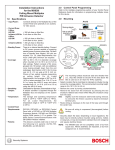
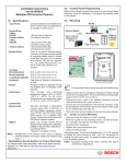
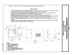
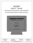
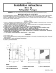
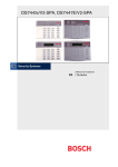
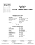
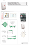
Installation Instructions
for the MX775
Multiplex PIR Intrusion Detector
1.0
Specifications
• Input Power: Connect to the Multiplex Bus of the control panel.
• Current Draw: Less than 200 micro-amps. Two milli-amps when in walk test mode
(LED on).
• Standby Power: There is no internal standby battery. Connect to DC power sources
capable of supplying standby power if primary power fails. Two hundred micro-amphours required for each hour of standby time needed. Eight hundred micro-amp-hours
minimum are required for U.L. Listed Requirements.
• Coverage:
Broad (standard)
50 ft. by 50 ft.
(15 m by 15 m)
Barrier*
80 ft. by 16 ft.
(24.4 m by 4.8 m)
Long Range*
120 ft. by 10 ft. (36.6 m by 3.1 m)
*Barrier and Long Range mirrors are available as options.
• Sensitivity: Standard, Intermediate or High.
• Tamper: A Tamper condition is signaled through the Multiplex Bus and displayed at the
keypads.
• Temperature: The storage and operating range is -20° to +120°F (-29° to +49°C). For
U. L. Listed Requirements, the temperature range is +32° to +120°F (0° to +49°C).
• Requirements: A DS7400, DS7400X, or DS7400Xi control panel with a DS7430 multiplex expansion module. The DS7400 and DS7400X require ROM version 1.07 or greater.
• Options: B328 Gimbal Mount Bracket, B333 Swivel Mount Bracket, TC6000 Test Cord.
NOTE: Misalignment of the detector when using an optional mounting bracket may
reduce range.
• U.S. Patent Number: #4,764,755.
2.0
• Before doing anything else, reconnect the MX775 (that coincides with the displayed
zone) to the multiplex bus of the DS7430. Press the [#/Command] button to continue
programming. The display will ask whether you are programming a sensor or a contact.
It will show the following:
• Press the [4] button to program the MX775 to the control panel.
• If the MX775 is successfully programmed, the keypad will increment to the next zone (if
there is one) pre-programmed as a multiplex zone. If the zone is unsuccessfully programmed, the keypad will sound a three-beep error tone.
Hint:
• Program the control panel using the DS7400, DS7400X or DS7400Xi Reference Guide.
Refer to the Zone Programming section in the control panel manual.
• Define the MX775’s address (zone number), its type (multiple zone input device), its
partition (1-4), and which zone function it will follow (1-15).
For example: Program zone 9 to be a single input (the MX775) in partition
1 that follows zone function 1.
Procedure:
Enter the Programmer’s Mode.
Enter address 0030 (DS7400 or DS7400X) or address 0026 (DS7400Xi).
Enter the data digits as [0] and [1] followed by the [#] button.
Exit the Programmer’s Mode.
Mark the zone numbers on each unit to assist with device location.
Disconnect the device you just programmed and connect the next device (that belongs to the displayed zone) to the multiplex bus of the
DS7430 and press the [#] button. Continue programming.
Any devices that are programmed as 24-hour zones will cause an
alarm when you exit the Programmer's Mode. Reports for these
zones will be sent if they are programmed.
Multiplex Programming
Before installing the MX775, its address and other information must be programmed into
the control panel.
•
•
•
•
- The display will then call-up the first zone you have pre-programmed to be a multiplex zone. To access a different zone, press the [*] key, then enter the three digit
address of the zone you want. The display will show the following:
• If no other zones have been pre-programmed, the display will show the following:
• If you wish to exit the Zone Programmer’s Mode, press the [*] button for 2 seconds. This
brings you back to the Programmer’s Mode. To exit the Programmer’s Mode, press the
[*] button for 2 seconds.
3.0
Mounting
• If you wish to use the BusLoc® feature you must program a 5 digit code (e.g. 5 4 3 2 1)
at programming address 9999. BusLoc® is a proprietary method of tying the multiplex
zones to the control panel to prevent the system from being taken over. Using BusLoc®
will program an invisible identification code into the multiplex zones. If you are not using
the BusLoc® feature skip the next procedure.
For example: Program the BusLoc® code to be 54321.
•
•
•
•
Procedure:
Enter the Programmer’s Mode.
Enter address 9999.
Enter the 5 digit code followed by the [#/Command] button (do not lose this code).
Exit the Programmer’s Mode.
• Once the pre-programming is done, you are ready to program the MX775.
• Disconnect all multiplex devices from the DS7430.
• Program the MX775 through the control panel.
- Enter the Programmer’s Mode.
- Enter the multiplex programming mode by entering [9] [9] [9] [5] followed by the [#]
button.
- The control will then take a few seconds to check the multiplex connection to confirm
nothing is connected to it.
The display will show the following:
Note:
The mounting surface should be solid and vibration free.
• Select a location that is most likely to intercept an intruder moving across the coverage
pattern. The recommended mounting height range is 6.5 ft. to 8.5 ft. (2 m to 2.6 m).
• Remove the cover. Insert a thin flathead screwdriver into the notch at the bottom of the
cover and pry up.
• Remove the circuit board/mirror unit from the enclosure. Push the board/mirror unit
toward the top of the enclosure until it clears its four retainer tabs, then lift it out.
• Open the knock-out wire entrance and route the wiring through.
Detection Systems, Inc., 130 Perinton Parkway
Fairport, New York, USA 14450-9199
(716) 223-4060 • (800) 289-0096 • Fax: (716) 223-9180
Copyright © 1997-1998 Detection Systems, Inc.
MX775 InstallationGuide P/N 35989C 3/98
6.0
Surface or Corner Mounting
• Open 2 holes for surface or corner mounting.
• Mark the location for the mounting screws. Use the enclosure as a template. Pre-start
the mounting screws.
• Firmly mount the detector.
• Replace the circuit board/mirror unit.
Select the Vertical Angle
• The angle adjust markings are on the mirror. Slide the mirror forward or back until the
angle hash marks are in-line with the markers on each side of the frame.
• Connect a DC VOM to the Noise Voltage pins.
- Set meter scale for about 5.0 VDC (use of the TC6000 is recommended).
• The base reference level for reading background noise is approximately 2.0 VDC.
- Installations in quiet environments will result in a steady reading between 1.9 and 2.1 VDC.
- Voltage changes greater than 0.75 VDC from the reference level are desirable for
good catch performance.
- If changes are less than +0.75 VDC, the device may fail to respond if the temperature
between the intruder and the background is minimal.
• Turn on all heating and cooling sources that would normally be in operation during times
of protection.
- Stand away from the unit and outside the coverage pattern, then monitor the background noise for at least three minutes.
- Readings should not deviate from the reference level more than ±0.15 VDC.
- For readings outside these limits; eliminate the cause, re-point the unit slightly, or
mask off the affected zones.
7.0
This chart will help you set the correct Vertical Angle based on the mounting height,
mirror type, and desired range.
4.0
Wiring
Final Tests
Other Information
• Maintenance: Consult the DS7400Xi User's Guide (P/N: 32781B) for the procedure on
performing a zone test. Performing a zone test on a regular basis assures an alarm
output prior to arming the system.
• Sealing The Wire Entrance: The foam plug provided is used to seal the wire entrance
from drafts and insects after installation.
• Mirrors: The mirror is adjustable +2 to -18° vertically and +10 to -10° horizontally. To
change the mirror, just pull it out from its resting grooves.
Note:
Excessive handling of the mirror surfaces may lead to performance degradation.
8.0
Coverage Patterns
CAUTION: Only apply power after all connections have been made and inspected.
• Connect wiring as shown.
Terminal Descriptions
• 1 (+), 2 (+), 3 (-) & 4 (-): Connect to the Multiplex Bus of the
control panel. Use no smaller than #22 AWG wire between the detector and the
control panel.
The program plugs are described as follows:
LED Operation
• ON: Allows the LED to operate when activated by alarm.
• OFF: The LED will not operate on alarm.
The LED is for Walk Test purposes only. Disable the LED
when Walk Testing is complete. To disable the LED, place the
jumper in the OFF position. To enable the LED (for future Walk
Testing), place the jumper in the ON position.
Sensitivity Mode
• Standard Sensitivity: Recommended setting for maximum false alarm immunity. Tolerates environment extremes on this setting. Not recommended
for Long Range or Barrier type patterns. The detector is shipped
in Standard Sensitivity mode.
• Intermediate Sensitivity: Recommended setting for any location where an intruder is expected to cover only a small portion of the protected area. Tolerates normal environments on
this setting. This setting will improve your intruder catch performance.
• High Sensitivity: Fast response to intruder signals. For use in
quiet environments where thermal and illumination transients
are not anticipated.
5.0
Setup and Walktesting
• Apply power to the unit.
• Wait approximately 3 minutes (with no motion in the coverage area)
for the detector to setup.
• Walk test across the coverage pattern.
• The edge of the coverage is determined by activation of the LED.
• Walk test the unit from both directions to determine the boundaries.
Page 2
Copyright © 1997-1998 Detection Systems, Inc.
MX775 Installation Guide