1
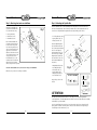
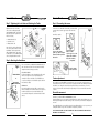
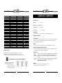
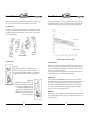
OWNER’S
MANUAL
Safety Notice..............2
Assembly & Usage 3-7
Exploded View ..........8
Parts List ..............9-10
Exercise Computer ..11
Owner’s Manual
This Product is Brought to You by:
IMPORTANT!
Please read all instructions
carefully before using this
product. Retain this manual
for future reference.
Thane International, Inc. La Quinta, CA 92253
Thane Direct Canada, Inc. Toronto, Ontario
Thane Direct UK Limited Admail ADM3996 London W1T 1ZU
www.thane.com
www.thanefitness.com
Making Fitness Fun!®
TYPE:BK2080
(9/02)
Thane International, Inc.
La Quinta, CA 92253
Thane Direct Canada, Inc.
Toronto, Ontario
Thane Direct UK Limited
Admail ADM3996 London W1T 1ZU
www.thane.com
Owner’s Manual
Owner’s Manual
IMPORTANT SAFETY NOTICE
Note the following precaution before assembling or operating the machine.
1. THE MAXIMUM WEIGHT CAPACITY OF THE ORBITREK ELITE IS 275 LBS (125 kgs).
Persons whose body weight exceeds this limit should NOT use this machine.
2. Keep children and pets away from the Orbitrek Elite at all times. DO NOT leave
unattended children in the same room with the machine.
3. Handicapped or disabled persons should not use the Orbitrek Elite without the presence
of a qualified health professional of a qualified health professional or physician.
4. If the user experiences dizziness, nausea, chest pain, or any other abnormal symptoms,
STOP the workout at once. CONSULT A PHYSICIAN IMMEDIATELY.
5. Before beginning training, remove all within a radius of 2 meters from the machine.
DO NOT place any sharp objects around the Orbitrek Elite.
6. Position the Orbitrek Elite on a clear, level surface away from water and moisture.
Place mat under the unit to help keep the machine stable and to protect flooring.
7. Use the Orbitrek Elite only for its intended use as described in this manual.
DO NOT use any other accessories not recommended by the manufacturer.
8. Assemble the machine exactly as the descriptions in the instruction manual.
9. Check all bolts and other connections before using the machine for the first time and
ensure that the trainer is in the safe condition.
10. Hold a routine inspection of the equipment.Pay special attention to components which
are the most susceptible to wear off, i.e.connecting points and wheels. The defective
components should be replaced immediately. The safety level of this equipment can only
be maintained by doing so. Please don't use the Orbitrek Elite until it is repaired well.
11. NEVER operate the Orbitrek Elite if it is not functioning properly.
ASSEMBLY INSTRUCTIONS
BEFORE you begin:
1.
Locate a comfortable work site. Assemble your OrbiTrek Elite in an open space with adequate
ventilation and lighting. Because the OrbiTrek Elite is portable, to some extent, you need not
assemble it exactly where it is to be used. For your convenience, however, you should avoid
hauling the machine across excessive distances, through narrow passage ways or over staircases
once its assembly is complete.
2.
It’s a good idea to flatten out the shipping carton, and use it as a work surface when you
assemble the OrbiTrek Elite. Keep a few paper towels handy since some of the components
are lightly pre-greased.
Notice:
Find your tools. You will need the following tools to assemble the Orbitrek Elite.
Ruler with both metric and English measurements
Allen wrench (6# and 8#)
Spanner
Before assembling please check whether all needed parts are available (at the above of this instruction
sheet you will you will find an exploded drawing with all single parts (marked with numbers) which this
item consist of.
Identify your hardware:
Organize your bolts and nuts before assembly. Nuts are identified by the diameter of the cavities.
For more information, refer to exploded view diagram and parts list on pages 8-10 of this manual.
12. This machine can be used for only one person’s training at a time.
13. Do not use abrasive cleaning articles to clean the machine. Remove drops of sweat
from the machine immediately after finishing training.
14. Always wear appropriate workout clothing when exercising. Running or aerobic shoes
are also required.
15. Before exercising, always do stretching first.
16. The power of the machine increases with increasing the speed, and the reverse.
The machine is equipped with adjustable knob, which can adjust the resistance.
WARNING: BEFORE BEGINNING THIS OR ANY EXERCISE PROGRAM, CONSULT YOUR PHYSICIAN
FIRST. THIS IS ESPECIALLY IMPORTANT FOR INDIVIDUALS OVER THE AGE OF 35 OR PERSONS WITH
PRE-EXISTING HEALTH PROBLEMS. READ ALL INSTRUCTIONS BEFORE USING THE ORBITREK ELITE.
THANE ASSUMES NO RESPONSIBILITY FOR PERSONAL INJURY OR PROPERTY DAMAGE SUSTAINED
BY OR THROUGH THE USE OF THIS PRODUCT.
SAVE THESE INSTRUCTIONS
2
NO.1 LEFT HINGE BOLT
NO.11 ARC WASHER (Ø8)
NO.20 BOLT (M8*45)
NO.93 ARC WASHER
(dl=16 D=26 s=0.3)
NO.42 RIGHT HINGE BOLT
NO.6 SPRING
WASHER (1/2”)
NO.7 LEFT LOCK NUT (1/2”)
NO.12 DOMED NUT (M8)
NO.13 NUT (M8)
NO.31 HINGE SCREW (3/8”*20)
NO.34 LOCKING
KNOB
ALLEN WRENCH 8#
NO.32 SPRING
WASHER ( 10)
NO.38 SPINDLE BAR
ALLEN WRENCH 6#
3
NO.9 CARRIAGE BOLT (M8*60)
NO.14 FLAT WASHER (Ø8)
NO. 33 D SHAPER WASHER
NO.89 RIGHT LOCK NUT (1/2”)
SPANNER
Owner’s Manual
Owner’s Manual
Step 1: Attaching front and rear stabilizers
Step 2: Attaching the Spindle Bar
Attach the Front Stabilizer (No.
23) and the Rear Stabilizer (No.
10) to the main frame using:
Insert the Spindle Bar (No. 38) through the Right Connecting Tube (No. 55) into the main frame,
into Left Connecting Tube (No. 24). Put a D Shaper Washer (No. 33) and a Spring Washer (No. 32)
on either side of the Spindle Bar and tighten both ends using the Hinge Screws (No. 31).
4 – Carriage Bolt (No. 9)
4 – Arc Washers (No. 11)
4 – Domed Nuts (No. 12)
Fig. 1
23
9
11
Place the Front Stabilizer (No.
23) against the main frame and
be sure the holes line up. Take
two of the Carriage Bolts (No. 9)
and pass them through the tube
supports located on the unit.
Slip the two Arc Washers (No. 11)
over the threaded portions of the
carriage bolts. Place the two
Domed Nuts (No. 12) over the
Arc Washers (No. 11) and firmly
tighten down the Domed Nuts
(No. 12) using the wrench provided.
11
2 – “D” Shaped Washers (No. 33)
2 – Spring Washers (No. 32)
2 – Hinge Screws (No. 31)
12
12
36
12
11
10
9
Notice: The Front Stabilizer (No. 23) has wheels for moving your Orbitrek Elite.
Follow the same procedure for attaching rear stabilizer.
Insert the Right Hinge Bolt
(No. 42) with the Arc Washer
(No. 93) through the Pedal Post
(No. 19 for the right side).
Put Spring Washer (No. 6) on
the bolt, then pass the Right
Hinge Bolt (No. 42) through
the Crank (No. 91) and secure
the bolt with the Right Lock
Nut (No. 89).
1 – Right Hinge Bolt (No. 42)
1 – Left Hinge Bolt (No. 1)
2 – Arch Washer (No. 93)
2 – Spring Washer (No. 6)
1 – Right Lock Nut (No. 89)
1 – Left Lock Nut (No. 7)
33
32
31
38
36
31
32
19
91
33
55
42
19
24
6
89
5
93
83
Fig. 2
1
93
5
7
6
#1: LEFT #42: RIGHT
Repeat this procedure for the
left side.
CORRECT
INCORRECT
ATTENTION:
INCORRECT
The Right and Left Hinge Bolt (No. 42 & No. 1) must fully penetrate the nylon ring inside the
Connecting Tube (No. 5) and the Right and Left Crank (No. 91 & No. 83). This will ensure the stability
and durability of you Orbitrek Elite.
In order to install hinge bolt properly, keep it perfectly straight as the bolt goes through the pedal
tubing and the crankshaft. If the hinge bolt is connected to the crankshaft at an angle, damage to
both the hinge and the crankshaft may occur.
4
5
Owner’s Manual
Owner’s Manual
Step 3: Tightening the Lock Nuts and Attaching the Pedals
Step 5: Connecting the sensor
Tighten the both sides of Lock Nuts
(No. 3) before assemblying the pedals.
Attach the Right Pedal (No. 26) and Left
Pedal (No. 27) to their respective Pedal
Tube (No. 19) using:
26
Fig. 3
20
36
19
27
BATTERY
14
13
37
Line up the holes in the pedal with the
holes on the pedal tube. Insert the Hex
Head Bolt (No. 20) through the holes.
Slide the Flat Washer (No. 14) and the
Lock Nut (No. 13) over the Hex Head Bolt
(No. 20) and tighten with the wrench.
13
14
SPANNER
3
To remove the computer,
pull the top, slide the computer
downwards and then pull from
tube bracket.
Step 4: Attaching the Handlebars
Fig. 4
DUAL ACTION
22
40
34
24
ATTACH HERE
FOR FIXED MODE
34
55
36
Fig. 5
Assembly is complete.
19
20
4 – Hex Head Bolt (No. 20)
4 – Lock Nut (No. 13)
4 – Flat Washer (No. 14)
Connect the sensor B1 & B2 as shown in Fig. 5, then install the
computer (No. 37) into the support tube of the main frame
(No. 36).
You can easily switch your Right and Left Handlebars (No. 22
& No. 40) between the dual-action mode and the fixed mode
during the fixed mode during your workout.
DUAL ACTION MODE
To allow the handlebars to move along with the pedals, attach
them to the coupler bars. Select a height setting that is
comfortable to the user and make sure both handlebars are
set at the same height. Lock each handlebar in place with lock
knob (No.34). See Fig 4.
FIXED MODE
To keep the handlebars stationary while you workout, attach
them to the tubing on the main frame between he coupler bars.
As with the dual-action mode. Set both handlebars at the
same comfortable height and secure them with the lock knob
(No. 34).
Battery assembly:
Open the upper cover of the
computer, then install the
battery into the battery
compartment.
36
Insert the computer
into the tube bracket.
Tension adjustment
The assembly of your Orbitrek Elite is now complete. As you try your exercises for the first time, you
should adjust the tension to the correct level before you begin your full workout. Turning the adjustment
knob allows you to change the tension level and vary the intensity of your workout as you exercise.
To increase tension turn the tension knob to the right and top decrease tension turn the tension knob
to the left.
Reversible movement
Remember, your Orbitrek Elite has REVERSIBLE movement!
Forward pedaling exercises your quadriceps (front thigh muscles), while backward pedaling targets your
hamstrings (back thigh muscles). Take advantage of these facts to make your workout less fatiguing and
more fun.
Note: Orbitrek Elite has two moveable wheels on the front stabilizer, which are easy for you to move your
training bike and the end cap on the rear stabilizer can adjust the parallelism.
6
CAUTION: MAKE SURE YOU HAVE TIGHTEN ALL THE BOLTS AND NUTS WELL BEFORE
BEGINNIG YOUR WORKOUT.
7
Owner’s Manual
Owner’s Manual
EXPLODED VIEW & PARTS LIST
35
35
93
93
8
NO.
1
2
3
4
5
6
7
8
9
10
11
12
13
14
15
16
17
18
19
20
21
22
23
24
25
26
27
28
29
30
31
32
33
34
35
36
37
38
39
40
41
42
43
44
45
46
47
48
49
50
51
52
53
54
55
56
57
58
NAME
LEFT HINGE BOLT
BUSHING I
LOCK NUT
STEEL BUSHING
CONNECTING TUBE
SPRING WASHER
LEFT LOCK NUT
ADJUSTABLE END CAP
CARRIAGE BOLT
REAR STABILIZER
ARC WASHER
DOMED NUT
LOCK NUT
FLAT WASHER
HEX HEAD BOLT
SCREW
LEFT HANDLEBAR COVER (L)
BUSHING 2
PEDAL TUBE
HEX HEAD BOLT
LEFT HANDLEBAR COVER (R)
RIGHT HANDLEBAR
FRONT STABILIZER
LEFT CONNECTING TUBE
FRONT END CAP
RIGHT PEDAL
LEFT PEDAL
HEX HEAD BOLT
WHEEL
LOCK NUT
HINGE SCREW
SPRING WASHER
D SHAPER WASHER
LOCKING KNOB
PLASTIC SLEEVE
MAIN FRAME
COMPUTER
SPINDLE BAR
FOAM GRIP
LEFT HANDLEBAR
HANDLEBAR END CAP
RIGHT HINGE BOLT
RIGHT HANDLEBAR COVER (L)
RIGHT HANDLEBAR COVER (R)
PLASTIC SLEEVE
END CAP
FIXING WASHER (L)
WASHER
COLLAR BALL
COLLAR HOUSING
FIXING WASHER <R>
WASHER
CRANK SHAFT
CHAIN WHEEL
RIGHT CONNECTIING TUBE
FLAT WASHER
LEFT CHAIN COVER
FIXING NUT
QUANTITY
1
10
4
4
2
2
1
2
4
1
4
4
4
4
4
2
1
4
2
4
1
1
1
1
2
1
1
2
2
3
2
2
2
2
2
1
1
1
2
1
2
1
1
1
2
2
1
1
2
2
1
1
1
1
1
3
1
2
9
SPEC
1/2"
28* 16*16
M10
28* 14*10
1/2"
1/2"
M8X60
50*1.5
M8
M8
Ø8
M10X55
ST4.2X19
28* 10*10
M8X45
50*1.5
2
10
M6X48
23* 6.2*32
M6
3/8"*20
10
33* 23*310
25.4*2
1/2"
30*30*1.5
40*2.8
17*146
d=3.2,P=6.35
Ø5
M10*1.0
Owner’s Manual
Owner’s Manual
59
60
61
62
63
64
65
66
67
68
69
70
71
72
73
74
75
76
77
78
79
80
81
82
83
84
85
86
87
88
89
90
91
92
93
NUT
FIXING BOLT
TENSION KNOB
NUT
FLYWHEEL
FLYWHEEL SHAFT
LITTLE CHAIN WHEEL
RIGHT CHAIN COVER
NUT
SPRING
DOMED NUT
END CAP
WOOLLY BLOCK
HEX HEAD BOLT
PLASTIC FRAME
RUBBER
LOCK NUT
SPRING COVER
LEFT LITTLE COVER
SCREW
RUBBER COVER
END CAP
FIXING NUT
FIXING TUBE II
LEFT CRANK
CHAIN
SENSOR
FIXING TUBE I
BEARING
ADJUSTABLE NUT
RIGHT LOCK NUT
SPRING WASHER
RIGHT CRANK
NUT
ARC WASHER
2
2
1
2
1
1
1
1
1
1
1
2
1
1
1
1
1
1
1
13
1
2
2
1
1
1
1
1
3
1
1
2
1
1
2
EXERCISE COMPUTER
M6
M6*55
M10*1
SPECIFICATIONS:
TIME (TMR)……………......00:00-99:59
7/8"
SPEED (SPD)...0.0-99.9KM/HorML/H
M6
DISTANCE (DST)……….0.00-999.9KM
M5X30
CALORIES (CAL)…………….……0-9999KCAL
M5
ST4. 2*12
32*10
M10*1.25
13.6* 10.3*25.5
13.6* 10.3*10.5
6000ZZ
14*35
1/2"
6
M12*1.25
d1=16 D=26 S=0.3
BATTERY DISPOSAL:
OPERATION PROCEDURES:
1. AUTO ON/OFF:
The system turns on when any key is pressed or when it receives an input from the speed sensor.
The processor turns off automatically when the speed sensor has no signal input or no key is
pressed for approximately 4 minutes.
2. RESET:
The unit can be reset by changing the batteries or pressing the MODE key for 3 seconds.
3. HOW TO PRESET TIME, DISTANCE & CALORIES:
To choose the SCAN or LOCK if you do not want the scan mode, press the MODE key when the
pointer on the function you want which begins blinking.
4. FUNCTIONS:
TIME:
The time of exercise will be displayed by pressing MODE key until brand TMR appears.
SPEED:
Current speed will be shown buy pressing MODE key until brand SPD appears.
DISTANCE: The distance of each workout will be displayed by pressing MODE key until brand
DST appears.
CALORIES: The calories burned will be displayed by pressing MODE key until brand CAL appears.
SCAN:
Automatic display of the following functions in the order shown:
TIME-SPEED-DISTANCE-CALORIES
Batteries should not be considered as regular garbage. As consumer you are
obliged to return finished batteries. The finished batteries can be returned to
a collection base at your residential area or at places where batteries can be bought.
WE RECOMMEND THE USE OF ALCALI-MANGAN BATTERIES.
You will find these symbols on batteries,
which contain harmful substances:
Pb = Battery contains lead
Cd = Battery contains cadmium
Hg = Battery contains mercury
KEY FUNCTION:
MODE: This key lets you to select and lock on to a particular function you want.
BATTERY:
This monitor uses one battery. If improper display on monitor,
Please reinstall the batteries to have a good result.
Pb
10
Cd
Hg
11
Owner’s Manual
Owner’s Manual
Using your Orbitrek Elite will provide you with several benefits. It will improve your physical fitness,
tone your muscles and in conjunction with a calorie controlled diet, help you lose weight.
This is the stage where you put the effort in. After regular use, the muscles in your legs will become
more flexible. Work at your own pace and be sure to maintain a steady tempo throughout. The rate of
work should be sufficient to raise your heartbeat into the target zone shown on the graph below.
1. The Warm-Up Phase
This stage helps get the blood flowing around the body and the muscles working properly. It will also
reduce the risk of cramp and muscle injury. It is advisable to do a few stretching exercises as shown
below. Each stretch should be held for approximately 30 seconds. Do not force or jerk your muscles
into a stretch. If it hurts, STOP.
INNER THIGH
STRETCHES
FORWARD
BENDS
CALF/ACHILLES
STRETCHES
OUTER THIGH STRETCHES
SIDE BENDS
This stage should last for a minimum of 12 minutes
though most people start at about 15-20 minutes.
2. The Exercise Phase
3. The Cool-Down Phase
Start Position
Stand on the left side of the bike, grasp the handlebars (under the
handlebar end caps about 100mm), then stride your left leg, place your
left foot on the left pedal, then stride your right leg, place your right foot on
the right pedal, adjust your hands and stand pose to a comfortable position.
This stage lets your cardio vascular system and muscles wind down. This is a repeat of the warm up
phase. First, reduce your tempo and continue at this slower pace for approximately 5 mintues before
you get off your Exercise Bike. The stretching exercises should now be repeated, again remembering
not to force or jerk your muscles into the stretch.
As you get fitter, you may need to train longer and harder. It is advisable to train at least three times
a week, and if possible to space your workouts evenly throughout the week.
MUSCLE TONING
Moving Position
Grasp the handlebars, then switch the handlebars to and
fro in tandem to move along with the pedals, do elliptical
cycle movement. Your Orbitrek Elite has reversable
movement. Forward pedalling emphasizes your
quadriceps muscle (front thighs), while backwards
pedalling emphasizes your hamstrings (back thighs).
Remember, if you want to change your movement
direction, stop movement first.
12
To tone muscle while on your RACING BIKE you will need to have the resistance set quite high.
This will put more strain on your leg muscles and may mean you cannot train for as long as you would
like. If you are also trying to improve your fitness you may need to alter your training program.
You should train as normal during the warm up and cool down phases, but towards the end of the
exercise phase you should increase the resistance making your legs work harder. You will have to
reduce your speed to keep your heart rate in the target zone.
WEIGHT LOSS
The important factor here is the amount of effort you put in. The harder and longer you work, the more
calories you will burn. This is effectively the same as if you were training to improve your fitness, the
difference being the goal.
13