1
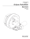
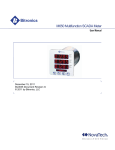
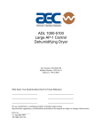
Instruction Manual 818
2/02
VeriFlame Single Burner
Monitoring System
Model 5600
Version 1.21
Modulation Model
No Purge Model
Purge Model
COPYRIGHT
Copyright 1997 by Eclipse Combustion, Inc. All rights reserved worldwide. This
publication is protected by federal regulation and shall not be copied,
distributed, transmitted, transcribed or translated into any human or computer
language, in any form or by any means, to any third parties, without the express
written consent of Eclipse Combustion, Inc., Rockford, Illinois, U.S.A.
DISCLAIMER NOTICE
In accordance with the manufacturer’s policy of continual product improvement,
the product presented in this brochure is subject to change without notice or
obligation.
The material in this manual is believed adequate for the intended use of the
product. If the product is used for purposes other than those specified herein,
confirmation of validity and suitability must be obtained. Eclipse Combustion,
Inc. warrants that the product itself does not infringe upon any United States
patents. No further warranty is expressed or implied.
We have made every effort to make this manual as accurate and complete as
possible. Should you find errors or omissions, please bring them to our attention
so that we may correct them. In this way we hope to improve our product
documentation for the benefit of our customers. Please send your corrections
and comments to our Marketing Communications Manager.
LIABILITY AND
WARRANTY
It must be understood that Eclipse Combustion’s liability for its products,
whether due to breach of warranty, negligence, strict liability, or otherwise, is
limited to the furnishing of burner monitoring system replacement parts and
Eclipse Combustion will not be liable for any other injury, loss, damage or
expenses, whether direct or consequential, including but not limited to loss of
use, income of, or damage to material arising in connection with the sale,
installation, use of, inability to use or the repair or replacement of Eclipse
Combustion’s products.
Eclipse Combustion, Inc., for a period of one year from shipment, warrants each
Veri-Flame burner monitoring system to the original purchaser to be free from
defects in material and workmanship under normal use as defined hereafter.
Any operation expressly prohibited in this Guide, any adjustment or assembly
procedures not recommended or authorized in these instructions, shall void
the warranty.
2
Eclipse Veri-Flame Instruction Manual 818 -2/02
About this manual
AUDIENCE
This manual has been written for the people who select and install the product
and the technicians who work on it. They are expected to have previous experience with this kind of equipment.
SCOPE
This manual contains essential information for the proper installation and operation of the Eclipse Veri-Flame Burner Monitoring System.
Following the instructions in this manual should assure trouble-free installation
and operation of the monitoring system. Read this manual carefully. Make sure
that you understand its structure and contents. Obey all the safety instructions.
Do not deviate from any instructions or application limits in this manual without written consent from Eclipse Combustion, Inc.
If you do not understand any part of the information in this manual, do not
continue. Contact your Eclipse sales office or Eclipse Combustion, Inc., Rockford, Illinois.
DOCUMENT
CONVENTIONS
There are several special symbols in this document. You must know their meaning
and importance.
The explanation of these symbols follows. Please read it thoroughly.
Danger:
Indicates hazards or unsafe practices which WILL result in severe
personal injury or even death.
Only qualified and well trained personnel are allowed to carry out
these instructions or procedures.
Act with great care and follow the instructions.
Warning:
Indicates hazards or unsafe practices which could result in severe
personal injury or damage.
Act with great care and follow the instructions.
Caution:
Indicates hazards or unsafe practices which could result in damage to the machine or
minor personal injury.
Act carefully.
Note:
Indicates an important part of the text.
Read the text thoroughly.
Eclipse Veri-Flame Instruction Manual 818 -2/02
3
HOW TO GET HELP
If you need help, you can contact your local Eclipse Combustion sales office.
You can also contact Eclipse Combustion, Inc. at:
1665 Elmwood Road
Rockford, Illinois 61103 USA
Phone: 815-877-3031
Fax: 815-877-3336
E-mail: [email protected]
http://www.eclipsenet.com
4
Eclipse Veri-Flame Instruction Manual 818 -2/02
Table of Contents
1
About this manual .....................................................................................
3
Table of contents ........................................................................................
5
Introduction ....................................................................................................
8
8
Product Description ...........................................................................................
2
Specifications ...............................................................................................
Introduction ............................................................................................................
Specifications ..........................................................................................................
Dimensions .............................................................................................................
3
DIP Switch Selection ..............................................................................
Introduction ............................................................................................................
DIP Switch Location .............................................................................................
DIP Switch Access .................................................................................................
No Purge DIP Switch Settings ...........................................................................
Modulation & Purge DIP Switch Settings ........................................................
4
Function Summary ..........................................................................................
Introduction ............................................................................................................
Standard Features ..................................................................................................
Combustion Air Flow Check .........................................................................
Main Fuel Valve Closed switch ......................................................................
Low Fire Start ...................................................................................................
High Fire/High Fire Purge Check .................................................................
Recycle Mode ....................................................................................................
Pilot Test Mode .................................................................................................
Interrupted or Intermittent Pilot .................................................................
Post Purge ..........................................................................................................
Spark, Pilot Flame & Main Flame Separation .............................................
System Error & Lockout Conditions ...........................................................
High to Low Fire Purge Modulation Capability with High to Low
Fire Position Switch Interlocks .....................................................................
9
9
9
9
12
12
12
12
12
13
14
14
14
14
14
14
14
14
14
15
15
15
15
16
Eclipse Veri-Flame Instruction Manual 818 -2/02
5
4
Optional Features .................................................................................................
Pilot Test Mode Sequence ..............................................................................
Air Switch Input Hold .....................................................................................
Remote Display & Power Supply ..................................................................
Status Lights & Push-buttons ..............................................................................
Interlocks Closed .............................................................................................
Air Failure ..........................................................................................................
System Error .....................................................................................................
Burner On ..........................................................................................................
Flame Failure .....................................................................................................
Low Fire ..............................................................................................................
High Fire .............................................................................................................
Auto .....................................................................................................................
Test/Reset ...........................................................................................................
16
16
16
16
17
17
17
17
17
17
17
17
17
17
5
System Installation ...................................................................................
18
18
18
18
18
19
19
19
19
19
20
20
21
Introduction ............................................................................................................
Interlocks and Limit Switch Input .....................................................................
Combustion Air Switch Input .............................................................................
Ignition Wiring ........................................................................................................
Low Fire Input ........................................................................................................
Main Valve Closed switch ....................................................................................
High Fire Input .......................................................................................................
Remote Reset ........................................................................................................
Remote Display & Power Supply .......................................................................
Purge and No Purge Wiring Diagram (Figure 5.1) ........................................
Modulation Wiring Diagram (Figure 5.2) ........................................................
Typical Connections for all Models (Figure 5.3) ............................................
6
Sensor Installation ....................................................................................
Introduction ............................................................................................................
Sensor Wiring .........................................................................................................
Flame Rods .............................................................................................................
Scanners ...................................................................................................................
Scanner Sighting Considerations .......................................................................
7
Test Procedures ...........................................................................................
Introduction ............................................................................................................
Flame Signal Strength ...........................................................................................
Minimum Pilot Test ................................................................................................
Pilot Flame Failure Test ........................................................................................
Main Flame Failure Test ........................................................................................
Spark Sighting Test .................................................................................................
Limits & Interlock Tests .......................................................................................
6
Eclipse Veri-Flame Instruction Manual 818 -2/02
24
24
24
25
25
25
26
26
26
26
27
27
27
27
8
Maintenance & Troubleshooting ....................................................
Introduction ............................................................................................................
Maintenance ............................................................................................................
Monthly Checklist .................................................................................................
Yearly Checklist .....................................................................................................
Troubleshooting .....................................................................................................
LED Status ..............................................................................................................
LED Status & Conditions for No Purge Models (Table 8.1) ......................
LED Status & Conditions for Purge Models (Table 8.2) ..............................
LED Status & Conditions for Modulation Models (Table 8.3) ...................
9
Remote Display Messages ...................................................................
Introduction ............................................................................................................
Veri-Flame Operating Sequence (Table 9.1) ...................................................
Remote Display Diagnostic Messages (Table 9.2) .........................................
Appendix ...........................................................................................................
Conversion Factors ..............................................................................................
Illustrated Parts List ..............................................................................................
28
28
28
28
28
29
30
30
31
32
33
33
34
38
41
41
42
Eclipse Veri-Flame Instruction Manual 818 -2/02
7
Introduction
1
PRODUCT
DESCRIPTION
The Eclipse Combustion Veri-Flame Single Burner Monitoring System controls
the start-up sequence and monitors the flame of single gas, oil, or combination
gas/oil burners. There are three different models to the Veri-Flame line: the no
purge, the purge and the modulation models. Each model features field selectable trial for ignition (TFI). Each model is also available for use with four types
of flame sensor: ultraviolet (UV), self-check UV, infrared (IR) and flame rod.
The Veri-Flame No Purge and Purge models are available in three different
series—5602, 5603 and 5605. The 5602 Series is UL listed, CSA certified, FM
approved and IRI acceptable; the 5605 Series is UL listed, FM approved and IRI
acceptable. The 5603 Series is for 240VAC applications not requiring US or
Canadian certifications.
The Veri-Flame Modulation model is available in two different series: 5602
and 5603. Both series are capable of modulation (high and low fire purging).The
5602 Series is UL listed, CSA certified, FM approved and IRI acceptable. The
5603 Series is for 240VAC applications not requiring US or Canadian certifications.
Figure 1 .1 Veri-Flame Single Burner Monitoring System (Purge Unit Shown)
8
Eclipse Veri-Flame Instruction Manual 818 -2/02
Specifications
2
INTRODUCTION
This section gives a detailed overview of Veri-Flame specifications and dimensions.
Specifications
PARAMETER
Supply
Temperature Ranges
DESCRIPTION
• Series 5602 & 5605: 120 VAC (+10%, -15%), 50/60 Hz standard.
Series 5603: 240 VAC (+10%, -15%), 50/60 Hz standard.
Internal power consumption: 12 VA (excluding external connected loads).
Unit
Model Nos.
Temperature Range
Veri-Flame
All Models
-40˚ to +60˚C (-40˚ to +140˚F)
90˚ U.V. Scanner
5600-90A
-20˚ to +60˚C
(0˚ to 140˚F)
U.V. Scanner
5600-91
-20˚ to +125˚C (0˚ to +257˚F)
NEMA4 UV Scanner
5600-91N4
-20˚ to +125˚C (0˚ to +257˚F)
I.R. Scanner
5600-92B
-40˚ to +110˚C (-40˚ to +230˚F)
UV/IR Scanner
5600-92SC
-20˚ to +80˚C (0˚ to +176˚F)
Self-Check U.V.
5602-91
-20˚ to +60˚C (0˚ to +140˚F)
Remote Display
5602DB
0˚ to 50˚C
(32˚ to 122˚F)
Remote Display
5602DBP
0˚ to 50˚C
(32˚ to 122˚F)
Flame Failure Response
3 seconds ±0.5 seconds.
Trial For Ignition (TFI)
No Purge & Purge Models:
Series 5602 & 5603: five or 10 seconds selectable.
Series 5605: ten or 15 seconds selectable.
Modulating Model: 5 or 10 seconds selectable
Pilot Interrupt (if selected)
10 seconds.
Purge Time
Selectable from 0-225 seconds in 15 second increments.
UL, CSA
Relay Contact Rating
Terminals
Inductive Load
Function
Resistive Load
Gas Valve
3, 5
175VA, 1/10 HP
10 amps
Ignition
4
375 VA
10 amps
Motor or Contactor
8
470 VA, 1/2 HP
16 amps
Output Ratings for 120 VAC
(maximum total connected
load not to exceed 15 amps)
Control Signal
Output Ratings for 240 VAC
(maximum total connected
load not to exceed 15 amps)
A, 10, 11, 12, 13
Function
Valves, Ignition
Motors or Contactor
Alarm
Control
Terminals
3, 4, 5,
8
A
10, 11, 12, 13
10 amps
175VA
Relay Contact Rating
Resistive Load
5 amps
16 amps
5 amps
5 amps
(continued onto next page)
Eclipse Veri-Flame Instruction Manual 818 -2/02
9
Specifications (continued)
PARAMETER
Approvals
(See chart below.)
DESCRIPTION
• No Purge & Purge Models:
Series 5602: UL listed, CSA certified, FM approved and IRI acceptable.
Series 5603: No approvals.
Series 5605: UL listed, FM approved and IRI acceptable.
• Modulating Models:
Series 5602: UL recognized (must be mounted in panel), CSA certified, FM
approved and IRI acceptable.
Series 5603: No approvals.
Shipping Weight
• 1.4 kilograms (3 lbs.) for all Veri-Flame models.
• 0.9 kilograms (2 lbs.) for Models 5602-10 & 5602-10-1 bases.
• 1.2 kilograms (2.6 lbs.) for Model 5602-40 base.
Approval Information
UL Listed, Guide No. MCCZ, File MH12613
UL Recognized, Guide No. MCCZ2, File MH12613
CSA Certified, Class No. 2632 01, File 37456
FM Approved, Class No. 7610, Report 1Y2A4.AF
Dimensions
Veri-Flame Unit/All Models
76mm
(3")
133mm
(5-1/4") Square
Veri-Flame Bases/Purge & No Purge Models
Model Number 5602-10
5.5mm
(7/32") Dia.
Mounting
Holes (4)
127mm
(5")
Square
38mm
(1-1/2")
10
Model Number 5602-10-1
127mm
(5")
Square
Knockouts
(10) for
13mm (1/2"
Conduit
102mm
(4") Square
13mm
(1/2")
Eclipse Veri-Flame Instruction Manual 818 -2/02
102mm
(4") Square
19mm
(3/4")
124mm
(4-7/8")
38mm
(1-1/2")
Dimensions (continued)
Veri-Flame/Modulating Model with Base Model Number 5602-40
24mm
(15/16")
171mm
(6-3/4")
25mm
(1")
1 2 3 4 5 6 7 8 A D S2 S1 10 11 12 13
40mm
(1-9/16")
5mm (3/16")
10mm (3/8")
213mm (8-3/8")
116mm
(4-9/16")
Remote Display Model Number 5602-DB
102mm
(4") Square
*
54mm
(2-1/8")
89mm
(3-1/2")
Square
Ground
Screw
Mounting
Bracket &
Screw (2)
Contrast
Adjustment
Screw
*
*
= Alternate Mounting Locations
Wiring
Terminal
15-pin Port
Terminal
24VDC Power Supply for Remote Display 5602-DB
44mm
(1-3/4")
70mm
(2-3/4")
79mm
(3-1/8")
Remote Display Model Number 5602-DBP
102mm
(4") Square
*
89mm
(3-1/2")
Square
54mm
(2-1/8")
Ground
Screw
Contrast
Adjustment
Screw
Mounting
Bracket &
Screw (2)
*
*
= Alternate Mounting Locations
Wiring
Terminals (2)
15-pin Port
Terminal
Eclipse Veri-Flame Instruction Manual 818 -2/02
11
DIP Switch Selection
3
INTRODUCTION
This section details the location, selection and description of the Veri-Flame
DIP switches, which allow for sequence and timing functions as well as system configuration.
Caution
To avoid electric shock, shut off the power supply when installing or removing any control
device. Flame monitoring systems must be installed by a qualified, licensed technician.
DIP Switch Location
All of the DIP switches are located in the back of each Veri-Flame unit (see Figure 3.1 on page 13, or the photograph on page 8).
DIP Switch Access
To gain access to the DIP switches, the Veri-Flame must be separated from the
back box (for visual reference, please refer to “Dimensions” on page 10). This
separation will expose the DIP switches on the back of the Veri-Flame unit.
No Purge
DIP Switch Settings
No Purge models of the Veri-Flame only use three of the eight DIP switches, as
shown in the labels in Figure 3.2 on page 13. They are as follows:
SW1: Recycling mode selection (On = Recycling; Off = Non-recycling)
SW2: Pilot selection (On= Intermittent, where pilot remains on during burner cycle;
Off =Interrupted, where pilot valve closes after main burner is established).
SW3: Trial-for-ignition (TFI) range selection (For 5602/5603 units: On =10
seconds; Off =5 seconds. For 5605 units: On =10 seconds; Off =15 seconds).
Modulation & Purge
DIP Switch Settings
Modulation and purge models of the Veri-Flame use all of the eight DIP switches,
as illustrated in Figure 3.2 on page 13. They are as follows:
SW1: Recycling mode selection (On = Recycling; Off = Non-recycling)
SW2: Pilot selection (On= Intermittent, where pilot remains on during burner cycle;
Off =Interrupted, where pilot valve closes after main burner is established).
SW3:Trial-for-ignition (TFI) range selection (For 5602/5603 units: On=10 seconds;
Off =5 seconds. For 5605 units: On =10 seconds; Off =15 seconds).
SW4 through 7: Purge time selection. Total purge time is the sum of each switch
selected.
SW8: Post purge selection. (On=15 second post purge).
12
Eclipse Veri-Flame Instruction Manual 818 -2/02
Figure 3.1 DIP Switch Location
Close-up of DIP switches on
back side of all Veri-Flame models.
Figure 3.2 DIP Switch Labels with Selections
No Purge Models
Purge Models
Modulation Models
Eclipse Veri-Flame Instruction Manual 818 -2/02
13
Function Summary
4
INTRODUCTION
This section describes the features of theVeri-Flame. It is broken into three categories:
Standard features, Optional features and the LED Indicator Lights on the front cover.
Refer to Figure 5.5 for sequence diagrams.
STANDARD FEATURES
The following function features are standard on the Veri-Flame models as noted:
Interlocks and Limit
Switch Input (Terminal 7)
This input is considered the normal operation control or run input to the VeriFlame system. Interlocks are generally pressure or temperature switches which,
when activated, start the burner. Limit switches are generally pressure, temperature and other switches which, when activated, stop the burner. The interlocks and
limit switches are wired in series. A break in this circuit will shut the burner down,
but will not produce an alarm.
Combustion Air
Switch Input (Terminal 6)
For purge and modulation models: This input is for monitoring the
combustion air switch separately from other interlocks and limits. The Veri-Flame
checks the air flow switch input is open before start-up, closed during operation,
and open again at burner shutdown, thus preventing operation with an air switch
that is defective, maladjusted or jumped. This input has about a 2 second delay to
filter out and ignore a momentary interruption.
The input will be proven open before start-up and after shutdown. If the input is
improperly powered before the fan output is energized, the system error light will
blink. The input must de-energize within 30 seconds or the Veri-Flame will lockout.
After the fan output has energized, the air switch input must be made within 10
seconds. If not proven, then the system will lockout, the alarm output and the air
failure light will come on. However, if the unit has the optional air switch input
hold feature, the sequence is held indefinitely without causing a lockout. When the
air switch input is made, then the sequence continues.
If the air switch opens during the main firing cycle, the system will either lockout
or recycle, depending on the DIP switch recycle selection.
Main Fuel Valve Closed
Switch (Terminal V)
Purge and No-Purge models: the Veri-Flame can be interlocked with the
main valve closed switch. This feature checks the switch position before
start-up and after shutdown to insure proper valve operation when the
jumper on the base is cut.
Low Fire Start
For modulation models: when wired, the system checks for the low fire start
position prior to light-off.
14
Eclipse Veri-Flame Instruction Manual 818 -2/02
Main Fuel Valve Closed/
High Fire Purge Check
(Terminal D)
For modulation models: This feature is enabled when the jumper on the
base is cut. The system checks that the high fire position switch and the
main valve closed switch are both made at the end of the high fire purge.
Recycle Mode
For all models: when selected, the Veri-Flame will restart the sequence after
flame or air failure. The recycle mode allows the system to re-initiate the startup sequence automatically provided the main burner has been operating for
at least 35 seconds. If the pilot flame fails to light during recycling, the system
will lock out and annunciate a pilot flame fail. If the recycle is successful and
the main burner is operational for at least 35 seconds, the system is ready for
another recycle. At no time will the system recycle in the event of pilot flame
fail.
Pilot Test Mode
For all models: this mode is entered by depressing the TEST/RESET button on
the front cover. In the pilot test mode, the Veri-Flame will hold the sequence once
the pilot flame is established (i.e., the main valve is not energized). When in the
pilot test mode, the green “Interlocks Closed” light blinks.
Test Mode
Run Mode
(Button In)
(Button Out)
To exit the pilot test mode, simply push the TEST/RESET button again and the
Veri-Flame will exit the pilot test mode (the green “Interlocks Closed” light
stops blinking but remains lit) and restart the sequence.
Interrupted or
Intermittent Pilot
For all models: pilot mode is selected using the DIP switch SW2. An interrupted pilot shuts off 10 seconds after the main valve opens. An intermittent
pilot continues during the entire main flame firing cycle.
Post Purge
For purge and modulation models: post purge is enabled by DIP switch
SW8. A post purge maintains the combustion air fan output for 15 seconds
after the interlocks and limit switch input have opened.
Spark, Pilot Flame &
Main Flame Separation
For all models: during the trial for ignition period (TFI), the pilot valve and
ignition coil remains energized. At the end of the TFI, the pilot flame remains
on and the ignition coil is de-energized. After a five second delay to prove the
pilot flame, the main gas valve is energized.
System Errors &
Lockout Conditions
A system error (illuminated by the red “System Error” LED on the front cover)
prevents gas ignition. The unit will continue its sequence after the error is cleared.
A lockout condition energizes the alarm output and de-energizes the gas valve
and ignition outputs. The unit must be reset to clear the alarm and start the
sequence. To reset, the button must be pressed twice so that the button is in
the out position.
The following system errors result in immediate lockout conditions:
1) Wiring error which puts external voltage on the output terminals (for
all models).
2) Welded internal contacts or other malfunctions in the Veri-Flame (for all
models).
3) Main fuel valve (for all models)–open after cycle shutdown or before
start-up. The system error light blinks twice and then remains on. The
fan output terminal 8 will energize.
Eclipse Veri-Flame Instruction Manual 818 -2/02
15
System Errors &
Lockout Conditions
(Continued)
4) Low fire fail (for modulating model)–low fire switch open prior to trial
for ignition.
5) High fire fail (for modulating model)–high fire switch is not closed at the
end of high fire purge.
The following situations will result in a lockout condition:
6) Air failure (for purge and modulation models) – loss of combustion air
anytime during the operational cycle. The Air Failure LED will be on for this
condition. (See “Recycle Mode”).
7) Pilot flame fail (for all models) loss of flame during the trial for pilot ignition
period. The Flame Failure LED will be on for this condition.
8) Main flame fail (for all models) loss of flame during the main burner trial for
ignition or run period (recycling not selected). The Flame Failure LED will be
on for this condition.
The following result in lockout conditions after 30 seconds, the system error
light blinks about 14 times and then remains on:
9) If a flame is detected out of sequence, which may be caused by:
a) a faulty scanner (for all models);
b) electrical interference on the sensor wiring (for all models);
c) a flame exists in the burner or in the line of sight of a scanner, due to
a gas leak, product fire or other condition (for all models).
10) Air flow switch closed before start-up (for purge and modulation models).
High to Low Fire Purge
Modulation Capability
with High to Low Fire
Position Switch Interlocks
For modulation models: the modulation feature incorporates a high fire purge
time and a low fire purge time into the purge sequence. This feature allows the
Veri-Flame to sequence internal dry contacts which can be used by the customer
requiring a high fire purge of the combustion chamber before ignition.
The high fire and low fire purge times are selectable by means of DIP switches
(see Section 3, “DIP Switch Settings” on page 12):
SW4 ................................ 15 seconds
SW5 ................................ 30 seconds
SW6 ................................ 60 seconds
SW7 ............................. 120 seconds
The selected times are additive and apply to both the high fire and low fire purge
times (that is, high and low fire times are always identical).
The modulation terminals will sequence as follows:
Sequence Step
Power Off
Power On, Limits Open
Purge To High Fire
Purge To Low Fire
Automatic Modulation
Alarm and Lockout
Internal Contact Connections
Terminal 10 (Common)
Terminal 10 (Common)
Terminal 10 (Common)
Terminal 10 (Common)
Terminal 10 (Common)
Terminal 10 (Common)
Terminal 11 (Auto)
Terminal 12 (Low Fire)
Terminal 13 (High Fire)
Terminal 12 (Low Fire)
Terminal 11 (Auto)
Terminal 12 (Low Fire)
The Automatic step occurs when the burners are operating and allows the
burner firing rate to be controlled by an automatic temperature controller.
16
Eclipse Veri-Flame Instruction Manual 818 -2/02
OPTIONAL FEATURES
The following features are available on select models, or when optional equipment
is purchased.
Air Switch Input Hold
For purge/modulation models: holds the sequence indefinitely until air switch
input is confirmed without affecting the air failure function and causing a lockout.
Remote Display &
Power Supply
Two models of remote display are available. The model 5602DB operates
on 24VDC and has no keypad. The model 5602DBP operates on
120VAC and has a keypad for reset function. The display is door panel
mounted and features a liquid crystal display in a ¼ DIN housing. The
unit connects to the Veri-Flame by a cable to the flame signal test jack,
and receives a serial communication on each sequence state change. The
display incorporates the following functions:
1) Provides status messages for the Veri-Flame sequence (see
section 9).
2) Indicates lockout conditions when they occur, as well as the
amount of time into the sequence when the lockout occurred
(see section 9).
Manual Reset on
Power Outage
3) Provides continuous monitoring of the burner’s flame signal
strength and run time during main burner operation.
This optional feature requires a reset on initial application of power or after an
interuption of power. The system error light blinks rapidly (about 4 times per
second) and a remote display will show “PUSH RESET TO START”. The reset
button must be pressed in and out to start
STATUS LIGHTS &
PUSH-BUTTON
All of the status lights and the TEST/RESET push-button are located on the front
cover of the Veri-Flame. This section describes their respective functions.
Interlocks Closed
For all models: this green LED illuminates when the operation limits are made.
These limits are wired in series to terminal 7. This input becomes energized to
begin the burner sequence. When in the test mode, this LED blinks (see “Pilot Test
Mode” on page 15).
Air Failure
For purge and modulation models: this red LED illuminates whenever combustion air is lost during the operational cycle of the Veri-Flame.
System Error
For all models: this red LED illuminates when a system error is detected (see
“System Errors & Lockout Conditions” on pages 15-16).
Flame Failure
For all models: this red LED illuminates when a pilot or main flame fails.
Low Fire
For modulation models: this yellow LED illuminates during the low fire period of the purge cycle.
High Fire
For modulation models: this red LED illuminates during the high fire period
of the purge cycle.
Auto
For modulation models: this green LED illuminates during the automatic period which occurs 20 seconds after the main valve is energized.
Test/Reset
For all models: this push-button is used to activate the pilot test mode or to
reset the Veri-Flame unit.
Flame Signal
For all models: this red LED is located behind the signal test port and illuminates when a flame signal is present.
Eclipse Veri-Flame Instruction Manual 818 -2/02
17
System Installation
5
INTRODUCTION
In this section, the necessary procedures are detailed to integrate a Veri-Flame into a
burner system; Figures 5.1 and 5.2 illustrate the various terminal strips mentioned.
Note:
Shut off the power supply before the Veri-Flame is removed or replaced from the base.
Caution:
Installation and maintenance must conform with the National Electrical Code and all
other national and local codes and authorities having jurisdiction. Flame monitoring
systems must be installed by a qualified, licensed technician.
Interlocks and
Limit Switch Input
Wire external interlock, control, and limit switches in series to this input. Guard
against induced voltage levels to wiring connected to this input. In some extreme
wiring runs, reduction of induced voltages may require a load (relay or light) connected
to terminal 7 to avoid system error lockouts. This input is the power source for the
valve and ignition output terminals. Be sure all switches wired to this input can handle
the current required by the total of all loads connected to terminals 3, 4,and 5.
Combustion Air
Switch Input
For purge and modulation models: Wire any switches and contacts in
series to this terminal for proving air flow function and relating to the air failure
light. Power must not be immediately present at terminal 6 when power is first
applied to terminals 1 or 7.
If this terminal is not used, place a jumper between the combustion blower output (terminal 8) and the air switch input (terminal 6).
If the combustion air blower is controlled outside of the Veri-Flame system, then
a three way solenoid valve must be connected between the air switch port and
the blower sensing port. The valve de-energized state should vent the switch
to ambient pressure. The energized state then connects the air switch to the
blower sensing port. Power the valve from the blower ouput terminal 8. If
accepted by local codes, the air switch could be wired between the combustion
blower output and the air switch input. Connecting the air switch in this manner will satisfy the open contact (air short) check on the switch.
18
Eclipse Veri-Flame Instruction Manual 818 -2/02
Ignition Wiring
Route ignition wiring a sufficient distance from all sensors and other low voltage wiring to avoid electrical interference, which may cause erratic operation
of the Veri-Flame system. Keep the high voltage wire run from the ignition transformer as short as possible. The best condition is to mount the ignition transformer close to the burner and keep a low impedance path from the burner
ground to the case of the transformer. Make sure the high voltage lead and
ground return paths do not create a loop antenna around the Veri-Flame and
sensor wiring.
Low Fire Input
For modulation models: it is possible to wire the system for checking low
fire start position prior to pilot ignition. To use this feature, the low fire start
switch must be connected between terminal 3 and the pilot valve (see Figure
5.2). On direct spark burners, a by-pass contact must be wired around the low
fire switch, see relay and contact CR in Figure 5.3.
Main Valve
Closed Switch
The system can be wired to check for the main valve closed switch on the main
gas valve prior to start-up and after the end of the burner cycle.
For purge and no purge models: the main valve closed switch must be connected to Terminal V and the jumper in the base must be cut (see Figure
5.4 on page 22).
For modulation models: the main valve closed switch must be wired in series between the air flow switch and the high purge damper switch (see Figure
5.1 on page 20). To use this feature, the jumper in the base must be
cut.
High Purge Input
For modulation models: the system can be wired to check for high purge
position during the high fire purge portion of the sequence. To use this feature, the red jumper in the base must be cut and the high purge position
switch must be connected from terminal 6 to D. If this feature is not used, the
jumper in the base remains intact or a jumper must be installed between terminals 1 and D. Please note that the yellow jumper on the base has no effect
whether cut or intact.
Remote Reset
This feature permits remote mounting of a switch to reset the Veri-Flame. To
use this feature, a normally closed remote reset switch must be wired so power
is interrupted to terminal 1. When it is depressed or actuated, the connection
to terminal 1 is momentarily interrupted and resets the Veri-Flame.
Remote Display &
Power Supply
Identify the model of remote display (see page 11) and wire according to figure
5.3. Mount through a ¼ DIN cutout using the two supplied brackets in either
the top and bottom or the side slots. Locate the display and wiring to minimize
electrical interference. Applying and disconnecting the display power supply
should coincide with power to terminal 1 of the Veri-Flame. Use the appropriate cable (Eclipse part #20318) to connect to the test jack and to the S2 terminal of the Veri-Flame wiring base. Do not attempt to parallel the test jack signal
to other devices when using a remote display. The LCD display contrast can be
adjusted on the back with a small blade screwdriver.
Eclipse Veri-Flame Instruction Manual 818 -2/02
19
Figure 5.1 No Purge and Purge Wiring Diagrams
Purge Models
No Purge Models
5602/5605:
120 VAC
50/60 HZ
5603:
240 VAC
50/60 HZ
5602/5605:
120 VAC
50/60 HZ
15 A On/Off
Fuse
15 A On/Off
Fuse
1
1
Interlocks & Limits
Piloted Burner
2
3
Pilot
3
Pilot
4
Ignition
4
Ignition
5
Main
5
Main
Air Flow Switch
6
A
Interlocks
& Limits
Alarm
V
7
8
Alarm
Proof of Closure
V
S1
G
S2
G
Figure 5.2 Modulation Wiring Diagram
5602/5605:
120 VAC
50/60 HZ
15 A. Fuse
5603:
240 VAC
50/60 HZ
On/Off
1
2
Low Fire Proving
Cut Red
Jumper
To Activate
Terminal D.
3
Pilot
4
Ignition
5
Main
6
7
Interlocks
& Limits
8
Fan
A
Alarm
D
Proof of
Closure
High Purge
Damper
Switch
S2
S1
10
11
12
13
Flame
Sensor
Terminals
Common
Automatic
Low Fire
High Fire
See the “High to
Low Fire Purge
Modulation
Capability” section
on page 16 for
contact connections.
G
20
Fan
A
S1
S2
Air Flow
Piloted Burner
2
7
Proof of
Closure
5603:
240 VAC
50/60 HZ
Eclipse Veri-Flame Instruction Manual 818 -2/02
Figure 5.3 Typical Connections For All Models
Model 5602 DBP
120 VAC Remote Display
Model 5602 DB
24 VDC Remote Display
12V 12V Tx
+
24V G Tx Rx G
Cable
#20318
PLUG
Flame Signal
Test Jack
To S2
120V 120V R1
L
N
Rx
R2
G
to 120 VAC
Cable
#20318
PLUG
Veri-Flame
To 1
Flame Signal
Test Jack
To S2
Veri-Flame
Power
Supply
#20317
N G
120/240VAC
U.V. / I.R.
S1
Blue (Signal)
S2 Yellow (Neutral)
Solid State U.V. / I.R.
U.V
or
I.R.
White
S1
Black
S2
G
A
B
C
D
S1
Scanner
Flame Rod
S2
Shield
Self Check U.V. 5602-91
(Requires 5602-91-7 cable)
2
1
S1
S2
Flame Rod
Blue
Direct Spark with
Low Fire Start
Direct Spark
3
4
3
MAIN
Low Fire Proving
IGNITION
5
MAIN
CR
Neutral
Note: Intermittent pilot must
be selected, DIP-SW2 = ON
4
5
IGNITION
CR
Neutral
Note: Intermittent pilot must be selected, DIP-SW2 = ON
CR is a control relay used to bypass the low fire switch after
the burner is lit.
Notes for Figures 5.1, 5.2 & 5.3:
1. Ground, shielding and conduit must not be connected to terminal S2.
2. Control circuit wires must meet 90°C (194°F) specification minimum and must
be No. 16 AWG or larger and in accordance with all applicable codes.
3. Flame sensor wires must be individually run in their own separate conduit;
flame sensor wires CANNOT be run together in a common conduit or wireway (See Section 6).
4. Flame signal should read between 4 and 10 VDC with a digital volt meter. Drop
off is approximately 4.0 VDC. Positive test jack point is on the cover marked
“Flame Signal” with negative point being the ground.
5. Purge time, TFI, intermittent/interrupted pilot, and recycle/non-recycle selections
are made with a DIP switch located on the rear plate of the control unit.
6. Neutral must be grounded.
Eclipse Veri-Flame Instruction Manual 818 -2/02
21
Figure 5.4 Purge and No Purge Bases
Model Number 5602-10
Internal Diagram
Purge & No-purge
Model Number 5602-10-1
P1
5
6
1
P1
4
P1 Fault Pilot P3
6
3
Ign P3
J1
5
Main P3
P3
3
5
6
S2
S1
7
8
3
4
V
2
1
A
3
2
1
1
Jumper
3
2
1
P1
Gnd
6
7
P3
4
P2
6
V
P1
6
Jumper
2
P2
Gnd
S1
Internal Diagram
Modulation Model
1
P1
5
6
P1
1
2
Fan
8
Red
1
J1
P3
J2
7
4
3
2
1
6
D
P1
6
4
2
Jumper
P1
4
P1 Fault Pilot P3
6
3
Ign P3
5
22K
Main P3
22K P3
3
4
P3
2
P2
Supervisor
2
Alarm
1
P2
5
Note: No purge models do not use 6 & 8.
Model Number 5602-40
1
4
Flame Signal Jack
Amplifier
P2
1
Modulating Base
6
3
Supervisor
S2
Ground Terminal
nnotNOTE:
present in plastic base.
3
2
1
A
P3
4
5 6 S2 S1 7 8 A 1 2 V 4 3
S2
S1
P2
1
Gnd
1 2 3 4 5 6 7 8 A D S2 S1 10 11 12 13
22
8
Alarm
P3
P2
P1
1
2
Fan
10
Eclipse Veri-Flame Instruction Manual 818 -2/02
J2
4
A
3
4
5
Flame Signal Jack
Amplifier
J2
Auto
2
11
J2
Low
1
12
J2
High
3
13
Ignition
5
Main Valve
7
Interlocks
V
POVC
Flame
Check
TFI
Outputs
Inputs
Terminal
Function
1
Control Power
3
Pilot Valve
4
Ignition
5
Main Valve
8
Fan
6
Air Switch
7
Interlocks
V
POVC
Prov
en
10
Sec
TFI
Outputs
Inputs
Function
1
Control Power
3
Pilot Valve
4
Ignition
5
Main Valve
8
Fan
6
Air Switch
7
Interlocks
D
High Fire & POVC
3
Low Fire Switch
Continuity 10 to 12
Between
Modulation 10 to 13
Terminals 10 to 11
35 Seconds
Main
Trial
10 Sec
Recycle
Permitted
Post
Purge
15 Sec
Firing
Cycle
Prov
en
Flame
Check
5 Sec
Pilot
Trial
Air
Star
t
Purge
Terminal
Recycle
Permitted
Firing
Cycle
Air
Star
t
Pilot
Trial
35 Seconds
Main
Trial
10 Sec
P
(Inte ilot Of
rmit f
tent
)
End
4
End
Pilot Valve
P
(Inteilot Off
rrup
ted)
Control Power
3
P
(Inte ilot Of
rmit f
tent
)
P
(Inteilot Off
rrup
ted)
Star
t
1
End
Inputs
Function
P
(Inteilot Off
rrup
ted)
Outputs
Terminal
P
(Inte ilot Of
rmit f
tent
)
Figure 5.5 Sequence Diagrams
Low Fire Purge
High Fire Purge
Automatic
10
Sec
Flame
Check
5 Sec
Pilot
Trial
TFI
High Fire
Purge
Low Fire
Purge
Main
Trial
10 Sec
Firing Cycle
Post
Recycle Purge
Permitted 15 Sec
20 Seconds
35 Seconds
Eclipse Veri-Flame Instruction Manual 818 -2/02
23
Sensor Installation
6
INTRODUCTION
This section describes the proper wiring, installation and sighting considerations for
all sensors that can be used with a Veri-Flame.
Warning
Incorrect sensor installation may cause the sensor to generate a
false flame signal, possibly resulting in the collection of unburned
fuel in the combustion chamber. This unburned fuel creates the
potential for explosions which can result in injuries, death and
property damage. Be certain that the flame sensor detects acceptable pilot and main flames only.
Sensor Wiring
Route sensor wiring a sufficient distance from ignition and other high voltage
or high current wiring to avoid electrical interference. Interference from
ground currents, nearby conductors, radio-frequency emitters (wireless divices),
and inverter drives can induce false flame signals. Shielded cables can help reduce interference with the shield connected to ground at the control end only.
The wire type and its capacitance (picofarads or microfarads) to ground may
cause low signal problems, so a grounded shield may decrease the signal due to
the cable’s internal capacitance. Multiple U.V. tube-type sensor leads run together without shielding may interfere or “cross talk”, so the shield or flexible
armor must be grounded to prevent this situation. For flame rod sensor runs
approximately 100 feet (30 meters) or greater, use Eclipse part number 21741
coax cable. To achieve the maximum wiring distance, the shield should not be
grounded (keep in mind that an ungrounded shield provides less protection
against electrical interference).
n
Flame Rods
24
Note:
Unshielded sensor wiring must not be run in common with other wires; it
must be run in separate conduit. Use #14 to #18 AWG wire suitable for
90°C (194°F) and 600 volt insulation. Multiple unshielded flame sensor
wiring must not be run together in a common conduit or wireway. Multiple
shielded flame sensor cables can be run in a common conduit.
Flame rods should be used only on gas burners. They accumulate soot on oil burners, causing nuisance shutdowns and unsafe operating conditions.
See the burner manufacturer’s literature for flame rod mounting location. When
installing flame rods, please consider the following:
Eclipse Veri-Flame Instruction Manual 818 -2/02
Figure 6.1 Flame Rod Position
WRONG
Rod Detects
Weak Pilot
CORRECT
Rod Detects
Only Strong
Pilot Flame
PILOT
1) Keep the flame rod as short as possible and at least 13 mm (1/2") away from
any refractory.
2) Position the rod into the side of both the pilot and main flames, preferably
at a descending angle to minimize drooping of the flame rod against burner
parts, as shown in Figure 6.1. Flame rod position must adequately detect
the pilot flame at all burner draft conditions. Extend the rod 13 mm (1/2")
into nonluminous flames, such as blue flames from burning an air/gas mixture. For partially luminous flames, such as atmospheric air/gas mixtures,
place the rod at the edge of the flame.
3) Provide a burner/flame grounding area that is at least four times greater than the
flame rod area contacting the flame. The flame rod/burner ground ratio and position of the rod in the flame may need adjustment to yield maximum flame signal
strength.
4) Ignition interference from the spark plug may increase or decrease the flame
signal strength. Reversing the ignition transformer primary leads may reduce
this effect. Changing the spark gap or adding grounding area between the flame
rod and spark plug may eliminate the interference.
Warning
Use only Eclipse scanner models as listed in the Illustrated Parts
List at the end of this document.
Scanners
When installing scanners, please consider the following:
1) Position the scanner within 457 mm (18") of the flame. Consult factory for
longer distances.
2) Bushing threads are 1/2 inch F.N.P.T. for all scanner models except 5602-91
which has 1 inch F.N.P.T. bushing threads.
3) The ambient temperature limits of each scanner varies; check the literature for
the specific scanner model. For higher temperatures, use Eclipse heat block
seal 23HBS for ½” N.P.T. scanners and if necessary, add cooling purge air.
4) An optional magnifying lens may also be used to increase the flame signal strength
in difficult sighting situations.
Scanner Sighting
Considerations
Figure 6.2 U.V. Scanner Sighting
MAIN
BURNER
Scanner
Sight
Line
1/3 of
Flame Length
SCANNER
Aim scanners at the third of the flame closest to the burner nozzle, as shown in
Figure 6.2 (oil flames typically have less UV radiation in the outer flame). The scanner should view the intersection of the pilot and main flames. When sighting scanners, please consider the following:
1) Sight the scanner away from the ignition spark. Sighting the spark or its reflections from burner internals can cause nuisance shutdowns during burner ignition. If necessary, use a scanner orifice to reduce spark pickup.
2) Do not allow the scanner to detect a pilot flame that is too small to ignite the
main burner.
3) Perform a minimum pilot test when installing or adjusting any pilot or main
burner system; see “Minimum Pilot Test” on page 26.
4) I.R. scanner model 5600-92B is ideal for oil flame applications. When used, aim
the I.R. scanner at the outer oil flame for flickering detection.
Eclipse Veri-Flame Instruction Manual 818 -2/02
25
Test Procedures
7
INTRODUCTION
This section describes the test procedures that must be performed after installation to insure that the Veri-Flame is operating properly; these procedures are
mandatory.
Flame Signal Strength
Insert the positive probe of a 0-15 VDC, digital volt meter into the test
point on the front cover of the Veri-Flame; connect the negative probe to
ground. A good flame signal strength will read between 6 and 11 VDC; anything below 4 VDC is inadequate. Also, the red LED inside the test point
illuminates when a flame signal is indicated.
Minimum Pilot Test
Run the following test procedures to ensure that the sensor will not detect a
pilot flame too small to reliably light the main flame:
1) Manually shut off the fuel supply to the burner, but not to the pilot.
2) Start the system normally.
3) To enter the pilot test mode, depress the test/reset button located in the
lower right corner on the front cover.
4) The control will hold the operating sequence at the pilot flame step. Measure signal strength as described above.
5) Reduce pilot fuel until the flame relay drops out. Increase pilot fuel until the
flame signal is greater than 4 VDC, and flame relay just manages to pull in.
This is the minimum pilot. If you don’t think this flame will be able to safely
light the main burner, realign the sensor so that it requires a larger pilot
flame and repeat steps 2 through 5.
6) Push the test/reset button located in the lower right corner on the front cover
to exit the test mode (reset) and begin the normal start-up sequence again.
7) When the sequence reaches the main flame trial for ignition, smoothly restore the fuel supply to the burner. If the main burner does not light within
five seconds, immediately shut off the burner supply to shut down the system. Realign the sensor so that it requires a larger pilot flame. Repeat steps
1 through 6 until the main burner lights off smoothly and reliably.
26
Eclipse Veri-Flame Instruction Manual 818 -2/02
Pilot Flame Failure Test
1) Manually shut off the fuel supply to the pilot and the main burner.
2) Place system in pilot test mode (please refer to page 15).
3) Start the system normally. The controller should lock out*; if it doesn’t,
then the controller is detecting a false flame signal (see Section 6). Find
the problem and correct it before resuming normal operation.
Main Flame Failure Test
1) Manually shut off the fuel supply to the main burner but not to the pilot.
(For Interrupted Pilot Systems)
2) Start the system normally. This should ignite the pilot and lock out* after
pilot interruption. If the system does not lock out, the controller is detecting a false flame signal (see Section 6). Find the problem and correct it before resuming normal operation.
Spark Sighting Test
1) Manually shut off the fuel supply to the pilot and the main burner.
2) Start the system normally.
3) Measure the flame signal as described in “Flame Signal Strength” in this section.
4) If a flame signal greater than 4 VDC is measured for more than three seconds during the trial for ignition, then the sensor is picking up a signal from
the spark plug; see “Sensor Wiring” on page 24.
Limits & Interlock Tests
Periodically check all interlock and limit switches by manually tripping them
during burner operation to make sure they cause the system to shut down.
Warning
Never operate a system that is improperly adjusted or has faulty interlocks or limit switches. Always replace faulty equipment with new
equipment before resuming operation. Operating a system with defective safety equipment can cause explosions, injuries, and property
damage.
* Indicated by the illuminated red “Flame Failure” LED on the Veri-Flame front cover.
Eclipse Veri-Flame Instruction Manual 818 -2/02
27
Maintenance &Troubleshooting
8
INTRODUCTION
This section is divided into two parts:
• The first part describes the maintenance procedures.
• The second part describes troubleshooting procedures, from identifying problems to interpreting the operating conditions by the lit LEDs on the front cover.
MAINTENANCE
Preventative maintenance is the key to a reliable, safe and efficient system. The
core of any preventive maintenance program is a list of periodic tasks.
In the paragraphs that follow are suggestions for a monthly list and a yearly list.
Note:
The monthly list and the yearly list are an average interval. If your environment is dirty,
then the intervals may be shorter.
Caution:
Turn off power before disconnecting or installing sensors, controls or modules.
Monthly Checklist
1. Inspect flame-sensing devices for good condition and cleanliness. Keep scanner lenses clean with a soft, damp cloth, since small amounts of dust will measurably reduce the flame signal strength. Wash the flame rod electrode and
insulator with soap and water, then rinse and dry thoroughly.
2. Test all the alarm systems for proper signals.
3. Check ignition spark electrodes and check proper gap.
4. Test interlock sequence of all safety equipment as described on page 27:
manually make each interlock fail, noting what related equipment closes or
stops as specified by the manufacturer.
Test flame safeguard by manually shutting off gas to the burner.
Yearly Checklist
1. Test (leak test) safety shut-off valves for tightness of closure.
2. Test pressure switch settings by checking switch movements against pressure setting and comparing with actual impulse pressure.
3. Visually check ignition cable and connectors.
4. Make sure that the following components are not damaged or distorted:
• the burner nozzle
• the spark plugs
• the flame sensors
• the flame tube or combustion block of the burner
28
Eclipse Veri-Flame Instruction Manual 818 -2/02
TROUBLESHOOTING
PROBLEM
Cannot initiate start sequence
POSSIBLE CAUSE
Main valve is not closed.
Air pressure switch has not made
contact.
SOLUTION
Check main valve closed switch.
No voltage on V (or D).
Check air pressure switch adjustment.
Check air filter.
Check blower rotation.
Check outlet pressure from blower.
No voltage on 6 after 8 is on.
High gas pressure switch has tripped.
Check incomming gas pressure; adjust gas
pressure if necessary.
Check pressure switch setting and
operation.
No voltage to 7.
Low gas pressure switch has tripped.
Check incomming gas pressure; adjust gas
pressure if necessary.
Check pressure switch setting and
operation.
No voltage to 7.
Malfunction of flame safeguard system
such as a shorted-out flame sensor or
electrical noise in the sensor line.
Have qualified electrician investigate and
rectify.
Purge cycle not completed.
Check switch settings.
Check air switch.
Main power is off.
Make sure power is on to control system.
No power to control unit.
Call qualified electrician to investigate.
Scrambled messages on remote display.
Electrical interference.
Check grounding in system.
Separate communication cable.
Move ignition circuit.
“UNSAFE AIR SHORT” message
appears on display.
Improperly adjusted air switch.
Air switch either shorted or wired
wrong.
Check air switch settings.
Check wiring to air switch.
Burner flame fails but no flame
failure indication occurs.
A faulty scanner.
Check scanner as explained in checklists in
“Maintenance” portion of this Section.
Improperly connected sensor wires.
Check wiring diagram on page 20 or 21 as
well as appropriate sensor information in
Section 6.
Electrical interference from other
current carrying wires.
Check Note information on page 24
regarding sensor wiring.
Improper grounding.
Check grounding of neutral at control
power transformer.
Voltage reading greater than
15VDC at “Test Point” on
Veri-Flame faceplate.
Eclipse Veri-Flame Instruction Manual 818 -2/02
29
LED STATUS
This section describes the status of operating conditions based on the LED or
combination of LEDs which are lit on the front cover of each Veri-Flame model.
Table 8.1 LED Status & Conditions for Veri-Flame No Purge Models
LED(S) LIT
POSSIBLE CAUSES
INTERLOCKS CLOSED
1) The interlocks are closed (normal operation), power on terminal 7.
SYSTEM ERROR
1)
2)
3)
4)
5)
6)
The flame detected is out of sequence, flame signal light is on.
The sensor is “runaway”, flame signal light is on.
Inductance is detected on sensor wires, flame signal light is on.
Voltage wired into terminals 3, 4 or 5.
Internal relay contacts welded.
Internal controller failure.
7) Main valve closed switch defective, no power to V.
FLAME FAILURE
1)
2)
3)
4)
5)
Pilot flame is not established in selected TFI.
Main flame is not established in selected TFI.
Main flame fails within 35 seconds of TFI.
Flame failed during operation in non-recycle mode.
Flame failed 35 seconds after TFI and was not established after try in recycle mode.
No Purge Model
30
Eclipse Veri-Flame Instruction Manual 818 -2/02
Table 8.2 LED Status & Conditions for Veri-Flame Purge Models
LED(S) LIT
POSSIBLE CAUSES
INTERLOCKS CLOSED
1) The interlocks are closed (normal operation), power on terminal 7.
SYSTEM ERROR
1)
2)
3)
4)
5)
6)
7)
8)
The flame detected is out of sequence, flame signal light is on.
The sensor is “runaway”, flame signal light is on.
Inductance is detected on sensor wires, flame signal light is on.
Voltage wired into terminals 3, 4 or 5.
Internal relay contacts welded.
Internal controller failure.
Air flow switch closed before start-up.
Main fuel valve switch opens after shutdown or before start-up, no power to V.
FLAME FAILURE
1)
2)
3)
4)
5)
Pilot flame is not established in selected TFI.
Main flame is not established in selected TFI.
Main flame fails within 35 seconds of TFI.
Flame failed during operation in non-recycle mode.
Flame failed 35 seconds after TFI and was not established after one try in recycle mode.
AIR FAILURE
1) Air flow switch not closed within ten seconds of start-up.
2) Air flow switch is open during timing cycle.
3) Air flow switch is open during firing cycle.
Purge Model
Eclipse Veri-Flame Instruction Manual 818 -2/02
31
Table 8.3 LED Status & Conditions for Veri-Flame Modulation Models
LED(S) LIT
POSSIBLE CAUSES
INTERLOCKS CLOSED
1) The interlocks are closed (normal operation), power on terminal 7.
SYSTEM ERROR
1)
2)
3)
4)
5)
6)
7)
8)
9)
The flame detected is out of sequence, flame signal light is on.
The sensor is “runaway”, flame signal light is on.
Inductance is detected on sensor wires, flame signal light is on.
Voltage wired into terminals 3, 4 or 5.
Internal relay contacts welded.
Internal controller failure.
Air flow switch closed before start-up.
High purge damper switch and/or main fuel valve switch opens during start-up.
Low fire switch not made before TFI.
FLAME FAILURE
1)
2)
3)
4)
5)
Pilot flame is not established in selected TFI.
Main flame is not established in selected TFI.
Main flame fails within 35 seconds of TFI.
Flame failed during operation in non-recycle mode.
Flame failed 35 seconds after TFI and was not established after try in recycle mode.
AIR FAILURE
1) Air flow switch not closed within ten seconds of start-up.
2) Air flow switch is open during timing cycle.
3) Air flow switch is open during firing cycle.
INTERLOCKS CLOSED and
AUTO
1) Burner in run mode, firing rate determined by automatic controller (normal operation).
INTERLOCKS CLOSED
and HIGH FIRE
1) Purge high sequence (normal operation).
INTERLOCKS CLOSED and
LOW FIRE
1) Purge low sequence (normal operation).
Modulation Model
32
Eclipse Veri-Flame Instruction Manual 818 -2/02
Remote Display Messages
9
INTRODUCTION
This section covers how the optional remote display is used with the Veri-Flame.
The remote display provides LCD messages which monitor the status of the VeriFlame’s functions as well as any lockout conditions. This section is divided into two
parts or tables:
• The first table describes the start-up and shutdown monitoring sequences of the
Veri-Flame and how the progress (or halt) of the sequence can be monitored by
the messages on the remote display.
• The second table alphabetically lists and explains the diagnostic messages which
can appear on the remote display.
Eclipse Veri-Flame Instruction Manual 818 -2/02
33
Table 9.1 Veri-Flame Operating Sequence
POWER ON
Was internal safe start check successful?
NORMAL MESSAGE
YES
REMOTE DISPLAY
REVISION X.X
NO
Various lockout messages
EXTERNAL INTERLOCK CHECKS
Is flame signal present?
ERROR MESSAGE #1
YES
UNSAFE FLAME ON
Fan is energized. If signal is eliminated within 30 seconds, sequence continues. If not, then . .
NO
FOR PURGE & MODULATING Is voltage present at air flow switch?
ERROR MESSAGE #1
YES
UNSAFE AIR SHORT
ERROR MESSAGE #2 – 30 SECONDS AFTER #1
UNSAFE FLAME ON
XX:XX:XX LOCKOUT
Is main valve closed switch made?*
NO
NO
ERROR MESSAGE
MAIN VALVE FAIL
XX:XX:XX LOCKOUT
If switch is opened within 30
seconds, sequence continues. If
not, then . . .
Alarm energized.
ERROR MESSAGE #2 – 30 SECONDS AFTER #1
UNSAFE AIR SHORT
XX:XX:XX LOCKOUT
Alarm energized.
Is voltage present at interlock switch?
YES
NORMAL MESSAGE
SAFE START OK
Check_Sum = XX
NO
ERROR MESSAGE
LIMITS OPEN
TIME = XXXX:XX:XX
Holds until answer is yes.
NORMAL MESSAGE
FAN ENERGIZED
Fan output is energized; modulator is sent to low fire.
BURNER START-UP
(see next page)
* Applies to purge and no purge models only.
34
YES
Eclipse Veri-Flame Instruction Manual 818 -2/02
Table 9.1 Veri-Flame Operating Sequence (continued)
BURNER START-UP
Is voltage present at air flow switch
within ten seconds?
NO PURGE MODELS
MODULATION MODELS
Is voltage present at air switch . . .
PURGE MODELS
NORMAL MESSAGE
Is voltage present at air switch . . .
AIR PROVEN
YES
NO
ERROR MESSAGE
NORMAL MESSAGE
AIR PROVEN
YES
AIR NOT PROVEN
XX:XX:XX LOCKOUT
NO
NORMAL MESSAGE
Purge based on selected time.
PURGE TO HIGH FIRE
ERROR MESSAGE
AIR NOT PROVEN
XX:XX:XX LOCKOUT
Modulator sent to high fire for
selected purge time.
Is voltage present
at high purge switch?
NORMAL MESSAGE
PURGE TO LOW FIRE
YES
NO
Modulator sent to low fire for
selected purge time.
ERROR MESSAGE
HI DAMPER FAIL
XX:XX:XX LOCKOUT
Is low fire switch closed?
NORMAL MESSAGE
YES
PILOT TRIAL FOR
IGNITION
Spark and pilot valve energized
for selected trial for ignition.
NO
ERROR MESSAGE
LOW FIRE FAIL
XX:XX:XX LOCKOUT
Is pilot flame signal present?
NORMAL MESSAGE
PILOT FLAME ON
YES
NO
ERROR MESSAGE
PILOT FLAME FAIL
XX:XX:XX LOCKOUT
Flame signal detected
NORMAL MESSAGE
PILOT FLAME XX.XV
TIME = XXXX:XX:XX
Spark turns off at end of TFI;
sequence delayed 5 seconds.
Is main flame signal present?
NORMAL MESSAGE
MAIN FLAME ON
YES
NO
ERROR MESSAGE
MAIN FLAME FAIL
XX:XX:XX LOCKOUT
Is flame signal present?
(see next page)
Eclipse Veri-Flame Instruction Manual 818 -2/02
35
Table 9.1 Veri-Flame Operating Sequence (continued)
BURNER START-UP (continued)
Is flame signal present?
YES
ERROR MESSAGE
NO
MAIN FLAME FAIL
XX:XX:XX LOCKOUT
NORMAL MESSAGE
MAIN FLAME ON
NORMAL MESSAGE
MAIN FLAME ON
PILOT OFF
Pilot will shut off 10 seconds
after main flame is energized.
IF Interrupted Pilot is selected
IF Intermittent Pilot Is Selected
NORMAL MESSAGE
MAIN FLAME ON
NORMAL MESSAGE
MODULATION MODELS
AUTOMATIC
MODULATION
Modulator sent to automatic 20
seconds after main valve is
energized.
MODULATION MODELS
NORMAL MESSAGE
PURGE & NO PURGE MODELS
BURNER ON XX.XV
TIME = XXXX:XX:XX
Main flame of burner is proven.
Flame signal = XX.XVolts DC;
elapsed time is shown in hours:
minutes:seconds.
PURGE & NO PURGE MODELS
Is flame signal present?
YES
NO
Is air switch signal on?
YES
NO
YES
YES
NO
Was the main flame on more
than 35 seconds?
YES
ERROR MESSAGE
36
NO
ERROR MESSAGE
MAIN FLAME FAIL
RECYCLING
Unit returns to beginning
sequence.
NO
AIR FAILURE
RECYCLING
Unit returns to beginning
sequence.
NO
Was the main flame on more
than 35 seconds?
Is recycle selected?
YES
Is recycle selected?
ERROR MESSAGE
AIR FAILURE
XX:XX:XX LOCKOUT
Eclipse Veri-Flame Instruction Manual 818 -2/02
ERROR MESSAGE
MAIN FLAME FAIL
XX:XX:XX LOCKOUT
Table 9.1 Veri-Flame Operating Sequence (continued)
BURNER SHUTDOWN
Shutdown is started by opening
the operating interlock circuit.
Is voltage present at interlocks?
YES
Continued operation.
NO
Is post purge selected?
YES
NO
NORMAL MESSAGE
POST PURGE
XX
Fuel valves de-energized; fan
energized for 15 seconds.
Is main valve closed switch made?*
YES
ERROR MESSAGE
NO
MAIN VALVE FAIL
XX:XX:XX LOCKOUT
Fan energized; alarm sounds.
FOR PURGE & MODULATING
ERROR MESSAGE #1
UNSAFE AIR SHORT
If switch is opened within 30
seconds, sequence continues. If
not, then . . .
Is voltage present at air flow switch?
YES
NO
Is flame signal present?
ERROR MESSAGE #1
UNSAFE FLAME ON
Fan is energized. If signal is eliminated within 30 seconds, sequence continues. If not, then . .
ERROR MESSAGE #2 – 30 SECONDS AFTER #1
YES
NO
NORMAL MESSAGE
LIMITS OPEN
TIME = XXXX:XX:XX
UNSAFE AIR SHORT
XX:XX:XX LOCKOUT
Alarm energized.
ERROR MESSAGE #2 – 30 SECONDS AFTER #1
UNSAFE FLAME ON
XX:XX:XX LOCKOUT
Alarm energized.
* Applies to purge and no purge models only.
Eclipse Veri-Flame Instruction Manual 818 -2/02
37
Table 9.2 Remote Display Diagnostic Messages (Listed Alphabetically)
MESSAGE
38
TYPE
EXPLANATION
AIR FAILURE
XX:XX:XX LOCKOUT
Lockout
For purge & modulation models: Combustion air flow limit
switch opened for more than two seconds once initially proven.
AIR FAILURE
RECYCLING
Status
For purge & modulation models: Combustion air flow limit switch
opened; if “recycle” has been selected, the Veri-Flame will restart the
sequence after air failure (see “Recycle Mode” on page 14).
AIR NOT PROVEN
XX:XX:XX LOCKOUT
Lockout
For purge & modulation models: Combustion air flow limit
switch did not make within ten seconds of fan being energized.
AIR PROVEN
Status
For purge & modulation models: Combustion air flow limit
switch closed within ten seconds of fan being energized.
AUTOMATIC
MODULATION
Status
For modulation models only: Modulating motor is sent to automatic operation.
BURNER ON XX.XV
TIME=XXXX:XX:XX
Status
Main flame of burner is proven in the automatic modulation mode;
flame strength is XX.XV (volts DC). Elapsed time is shown in
hours:minutes:seconds.
D-INTERNAL FAIL
XX:XX:XX:XX LOCKOUT
Lockout
For modulation models only: Internal control failure; replace
controller.
FAN ENERGIZED
Status
For purge & modulation models: Blower motor is energized
at the start of pre-purge.
FLAME FAILURE
XX:XX:XX LOCKOUT
Lockout
Main flame lost during operation in the automatic modulation mode.
Burner number (X) given of failed unit.
HI DAMPER/POVC
XX:XX:XX LOCKOUT
Lockout
For modulation models only: High damper or high purge rate
switch did not make at the end of pre-purge to high fire.
K-INTERNAL FAIL
XX:XX:XX LOCKOUT
Lockout
Internal control failure; replace controller.
L-INTERNAL FAIL
XX:XX:XX LOCKOUT
Lockout
Internal control failure; replace controller.
LIMITS OPEN
TIME=XXXX:XX:XX
Status
The controller has completed its internal checks and is standing by
for the interlocks to close.
LOW FIRE FAIL
XX:XX:XX LOCKOUT
Lockout
For modulation models only: Low fire switch is open just prior
to pilot trial for ignition.
MAIN FLAME FAIL
XX:XX:XX LOCKOUT
Lockout
Main flame was not established during the main burner trial for
ignition.
MAIN FLAME FAIL
RECYCLING
Status
Main flame lost during automatic modulation; control will recycle
once if “recycle” has been selected.
Eclipse Veri-Flame Instruction Manual 818 -2/02
Table 9.2 Remote Display Diagnostic Messages (continued)
MESSAGE
TYPE
EXPLANATION
MAIN FLAME ON
Lockout
Main valve has been energized and main flame proven during trial
for ignition.
MAIN FLAME ON
PILOT OFF
Status
Pilot valve is de-energized and main flame is on.
MAIN VALVE FAIL
XX:XX:XX LOCKOUT
Lockout
For purge and no purge models: Main valve closed switch is
open before start-up or after burner shutdown.
NO PURGE SELECT
XX:XX:XX LOCKOUT
Lockout
For purge & modulation models: No purge time was selected;
lockout prior to purge to high fire.
PILOT FLAME FAIL
XX:XX:XX LOCKOUT
Lockout
Pilot flame was not established during the pilot trial for ignition.
PILOT ON
Status
Pilot flame is proven; transformer is de-energized; remaining countdown for pilot trial for ignition is.
PILOT TRIAL FOR
IGNITION
Status
Pilot valve and ignition transformer are energized; countdown for
pilot trial for ignition begins.
POST PURGE
Status
For purge & modulation models: 15 second post purge is
started on burner shutdown.
PROGM SWITCH ERR
XX:XX:XX LOCKOUT
Lockout
DIP switch improperly set or changed during cycle.
PURGE TO HIGH
FIRE
Status
For modulation models only: Modulating motor is sent to high
fire.
PURGE TO LOW
FIRE
Status
For modulation models only: Modulating motor is sent to low
fire.
RELAY FAIL
XX:XX:XX LOCKOUT
Lockout
Internal relay(s) fail initial check. Check ratings. If lockout still occurs after overload is eliminated, replace control.
SAFE START OK
Status
Control has completed internal safe-start check.
UNSAFE AIR SHORT
Status
For purge & modulation models: Combustion air switch is closed
before start-up or after shutdown; control holds start-up until switch
reopens; if interlocks close before switch opens, alarm is energized.
UNSAFE AIR SHORT
XX:XX:XX LOCKOUT
Lockout
For purge & modulation models: Same conditions as above,
except the interlocks close before the switch reopens, causing a
lockout and the alarm being energized.
Eclipse Veri-Flame Instruction Manual 818 -2/02
39
Table 9.2 Remote Display Diagnostic Messages (continued)
MESSAGE
40
TYPE
EXPLANATION
UNSAFE FLAME ON
Hold
Flame signal—actual, induced, or runaway scanner—is detected before start-up or after shutdown. The fan is energized. If the cause is
corrected within 30 seconds, as in afterburn, the control will turn
off the fan and continue the sequence.
UNSAFE FLAME ON
XX:XX:XX LOCKOUT
Lockout
Same conditions as above, except the cause has not been corrected
within 30 seconds, resulting in a lockout and the alarm being energized.
UNSAFE–FLM–PURGE
Hold
For purge & modulation models: Flame signal—actual, induced,
or runaway scanner—is detected during the selected purge time
period. The fan is energized. If the cause is corrected within 30 seconds, as in afterburn, the control will turn off the fan and continue
the sequence.
UNSAFE–FLM–PURGE
XX:XX:XX LOCKOUT
Lockout
For purge & modulation models: Same conditions as above,
except the cause has not been corrected within 30 seconds, resulting
in a lockout and the alarm being energized.
V–INTERNAL FAULT
XX:XX:XX LOCKOUT
Lockout
Internal control failure; replace controller.
WATCHDOG FAIL
XX:XX:XX LOCKOUT
Lockout
Internal control failure; replace controller.
XXXXXXX
XXXXXTESTXX
Status
In combination with other messages, shows the control is in the
minimum pilot test mode.
Eclipse Veri-Flame Instruction Manual 818 -2/02
Appendix
CONVERSION
FACTORS
Metric to English.
FROM
TO
3
MULTIPLY
3
cubic meter (m )
BY
cubic foot (ft )
35.31
cubic meter/hour (m /h)
cubic foot/hour (cfh)
35.31
degrees Celsius (°C)
degrees Fahrenheit (°F)
kilogram (kg)
pound (lb)
(°C x 1.8) + 32
2.205
kilowatt (kW)
Btu/hr
3414
meter (m)
foot (ft)
3.28
millibar (mbar)
inches water column ("wc)
0.401
millibar (mbar)
pounds/sq in (psi)
14.5 x 10⁻³
millimeter (mm)
inch (in)
3.94 x 10⁻²
FROM
TO
MULTIPLY BY
kiloPascals (kPa)
millibar (mbar)
10
meter (m)
millimeter (mm)
1000
millibar (mbar)
kiloPascals (kPa)
0.1
millimeter (mm)
meter (m)
0.001
FROM
TO
MULTIPLY BY
Btu/hr
kilowatt (kW)
0.293 x 10⁻³
cubic foot (ft3)
cubic meter (m3)
2.832 x 10⁻²
cubic foot/hour (cfh)
cubic meter/hour (m3/h)
degrees Fahrenheit (°F)
degrees Celsius (°C)
2.832 x 10⁻²
(°F – 32) ÷ 1.8
foot (ft)
meter (m)
0.3048
inches (in)
millimeter (mm)
25.4
inches water column ("wc)
millibar (mbar)
2.49
pound (lb)
kilogram (kg)
0.454
pounds/sq in (psi)
millibar (mbar)
68.95
3
Metric to Metric.
English to Metric.
Eclipse Veri-Flame Instruction Manual 818 -2/02
41
ILLUSTRATED PARTS
LIST
Category
Pos.
No.
1
2
3
4
5
1
Sensors
6
6
7
2
8
9
10
3
Bases
11
Test
12
4
Display
Model
Number
Part
Number
Straight U.V. scanner
NEMA 4 U.V. scanner
90˚ U.V. scanner
I.R. scanner
Self-check scanner
Solid-state U.V./I.R. scanner
10-foot cable for self-check scanner
Scanner support (max. temp. 220˚F) (1)
Scanner support (max. temp. 475˚F) (1)
Magnifying lens assembly
Lens, magnifying
Lens, non-magnifying (2)
Insulated coupling
Cable, coax, RG62A/U for flame rod
Internal terminal base, metal
Exposed terminal base, metal
Internal terminal base, plastic
Adapter Base RA890
Adapter Base R4795
Modulation base
Screw, mounting to plastic base
Screw, mounting to metal base
5600-91
5600-91N4
5600-90A
5600-92B
5602-91
5600-92SC
5602-91-7
5600-90A SS
5600-90A SSH
5600-98
49600-91
20898
49600-90
49600-92
49602-91
21349
49602-91-7
20722
20723
49600-98
49600-99
18165
49099
21741
49602-10
49602-10-1
22194
49602-12
49602-14
49602-40
22110
22385
Tester for Veri-Flame units
Relay module (3)
5602
5602-40-4
49602
49240-2
Remote display, 24V
Remote display, 120VAC with keypad
Power supply, 24VDC (4)
Cable for remote display
5602 DB
5602 DBP
20316
20896
20317
20318
Description
5600-99
5602-10
5602-10-1
5602-10-P
5602-12
5602-14
5602-40
(1) For 90º U.V. scanner (Model No. 5600-90A), I.R. scanner (5600-92B), and solid state U.V./I.R. scanner (5600-92SC)
(2) For magnifying lens assembly (Model No. 5600-98), and self-check scanner (5602-91)
(3) Used to test modulation controls on tester (Model No. 5602) above.
(4) To be used with 20316 display only (not 20896).
5
6
7
11
9
8
12
10
Instruction Manual 818 2/02
Litho in USA