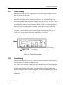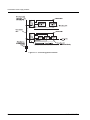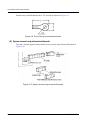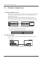
1
Front Cover
C120-H007-06EN
SPARC M10 Systems/
SPARC Enterprise/
PRIMEQUEST
COMMON INSTALLATION PLANNING
MANUAL
FOR SAFE OPERATION
Handling of This Manual
This manual contains important information regarding the use and handling of this
product. Read this manual thoroughly. Use the product according to the instructions
and information available in this manual. Keep this manual in hand for further
understanding.
Fujitsu makes every effort to prevent users and bystanders from being injured or from
suffering from damages to their property. Use the product according to this manual.
ABOUT THIS PRODUCT
This Product is designed, developed and manufactured as contemplated for general
use, including without limitation, general office use, personal use and household use,
but is not designed, developed and manufactured as contemplated for use
accompanying fatal risks or dangers that, unless extremely high safety is secured,
could lead directly to death, personal injury, severe physical damage or other loss
(hereinafter "High Safety Required Use"), including without limitation, nuclear
power core control, airplane control, air traffic control, mass transport operation
control, life support, weapon launching control. You shall not use this Product without
securing the sufficient safety required for the High Safety Required Use. If you wish
to use this Product for High Safety Required Use, please consult with sales
representatives in charge before such use.
RADIO FREQUENCY INTERFERENCE STATEMENT
The following notice is for EU users only.
WARNING: This is a product which meets Class A of EN55022. In a domestic
environment this product may cause radio interference in which case the user may
be required to take adequate measures.
The following notice is for USA users only.
This equipment has been tested and found to comply with the limits for a Class A
digital device, pursuant to Part 15 of the FCC Rules. These limits are designed to
provide reasonable protection against harmful interference when the equipment is
operated in a commercial environment. This equipment generates, uses, and can
radiate radio frequency energy and, if not installed and used in accordance with the
instruction manual, may cause harmful interference to radio communications.
Operation of this equipment in a residential area is likely to cause harmful
interference in which case the user will be required to correct the interference at his
own expense.
C120-H007-05EN
TRADEMARKS ACKNOWLEDGEMENTS
z UNIX is a registered trademark of The Open Group in the United States and other
countries.
The contents of this manual shall not be disclosed in any way or reproduced in any
media without the express written permission of Fujitsu Limited.
All Rights Reserved, Copyright © FUJITSU LIMITED 2002-2011
C120-H007-05EN
Revision History
(1/1)
Edition
01
02
Revised section
Details
(Added/Deleted/Altered)
2002-10-31
⎯
⎯
2005-09-15 Entire manual (Altered)
• Technical brush-up
• Modification of the manual title
• Addition of PRIMEQUEST
Date
Section 3.3.2
(Altered/Added)
• Modification of the concept of units
operational grouping
• Addition of description for concentration
of small equipment
Section 5.2.2 (Added)
• Addition of conditions for using mobile
phones
• Modification of manual title
• Addition of description for SPARC
Enterprise
• Deletion of description for
PRIMEPOWER
• Modification of tolerable limit of
Hydrogen sulfide gas
• Technical brush-up
03
2008-04-16 Entire manual (Altered)
04
2009-12-15 Section 4.3.5 (Altered)
05
2011-11-25 Entire manual (Altered)
Note:
C120-H007-05EN
Section 2.2.1 (Altered)
• Modification of the value for vibrations
during earthquakes
Section 4.3.5 (Altered)
• Modification of Table4.4
Section 4.3.6 (Added)
• Addition of the seawater (salt damage)
• Modification of the value for withstanding
a horizontal seismic intensity
Section 8.2.2 (Added)
• Addition of consulting department of an
earthquake preparedness
Reader's Comment Form
(Altered)
• Modification of the address for sending
back of the form
In this table, devised section is indicated by its section number in the
current edition.
An asterisk (*) indicates a section in the old edition.
Preface
1
This manual describes the requirements and concepts of installation and facility
planning that pertain to the setup of SPARC Enterprise and PRIMEQUEST.
Installation and facility planning requires full review with Fujitsu representatives in
charge according to the instructions presented herein.
This manual is intended for site planners preparing for the server system installation.
Use this manual to review server system installation plans or to run and administer the
server system. The reader is assumed to have some knowledge or experience in the
server system installation planning.
Contents and Organization of This Manual
This manual consists of 8 chapters, one appendix, one acronyms and abbreviations
section, and one index as below:
The manual contains general information and precautions required for the server
system installation plans. For information about specific SPARC Enterprise models
and PRIMEQUEST models, refer to the respective Installation Planning Manual.
CHAPTER 1 Installation Planning Overview
This chapter describes general requirements for the server system installation
planning and for the facilities used to house the server systems.
CHAPTER 2 Installation Sites
This chapter describes the recommended sites and structures and the buildings in
which the server systems can be installed, and the structures of the computer rooms.
CHAPTER 3 Equipment Layout
This chapter describes the procedures and precautions to take in laying out the server
system equipment.
CHAPTER 4 Air Conditioning
This chapter describes the available computer room air conditioning methods, along
with their features, conditions of air conditioning, and precautions.
CHAPTER 5 Electromagnetic Environment and Static Electricity
This chapter describes the electromagnetic environmental conditions relevant to
server systems, and electrostatic effects.
C120-H007-05EN
i
Preface
CHAPTER 6 Power Supply Facilities
This chapter describes the power supply requirements, power supply facilities,
grounding plans, power distribution boards, and power distribution routes for the
server systems.
CHAPTER 7 Protection Against Lightning
This chapter describes the safeguards necessary to protect server systems against
destructive lightning surge voltages.
CHAPTER 8 Security Actions
This chapter describes the actions necessary to ensure server system security.
Appendix A Conversion Information
This appendix provides quick reference tables for measure units conversion and
fractional decimal equivalent conversions.
Acronyms & Abbreviations
This acronyms and abbreviations provides complete word(s) of acronyms and
abbreviations used in this manual.
Index
This index provides the keywords, along with the reference page numbers so that
users can find the necessary information at a glance.
ii
C120-H007-05EN
Preface
Other Reference Manuals
When installing the SPARC Enterprise or PRIMEQUEST, read the installation guide
for each model first.
For the readers
• If you find any inconvenience with the description or incorrect explanation in this manual, please
fill in the "Comment Form" sheet at the back of this manual and forward it to the address
described on the sheet.
• This manual is subject to be revised without prior notice.
C120-H007-05EN
iii
Contents
..........................................................................
1
Preface . . . . . . . . . . . . . . . . . . . . . . . . . . . . . . . . . . . . . . . . . . . . . . . . . . . . . . . . . . . . . . . . . . .
i
CHAPTER 1 Installation Planning Overview . . . . . . . . . . . . . . . . . . . . . . . . . . . . . .
1
1.1 Office Installation and Computer Room Installation . . . . . . . . . . . . . . . . . . .
1.1.1 Office installation . . . . . . . . . . . . . . . . . . . . . . . . . . . . . . . . . . . . . . . .
1.1.2 Computer room installation . . . . . . . . . . . . . . . . . . . . . . . . . . . . . . . . .
1.2 Computer Room Installation Planning . . . . . . . . . . . . . . . . . . . . . . . . . . . . . .
1.2.1 Device support planning . . . . . . . . . . . . . . . . . . . . . . . . . . . . . . . . . . .
1.2.2 Support staff assignment . . . . . . . . . . . . . . . . . . . . . . . . . . . . . . . . . .
1.3 Preparing Building and Facilities . . . . . . . . . . . . . . . . . . . . . . . . . . . . . . . . . .
1.3.1 Building and facilities needed to install a server system . . . . . . . . . .
1.3.2 Furnishings accompanying a server system . . . . . . . . . . . . . . . . . . .
1.3.3 Rooms needed to run the server system . . . . . . . . . . . . . . . . . . . . . .
1.4 Scheduling . . . . . . . . . . . . . . . . . . . . . . . . . . . . . . . . . . . . . . . . . . . . . . . . . . .
1
1
2
3
3
3
4
4
4
5
5
CHAPTER 2 Installation Sites . . . . . . . . . . . . . . . . . . . . . . . . . . . . . . . . . . . . . . . . . . . .
7
2.1 Building Location . . . . . . . . . . . . . . . . . . . . . . . . . . . . . . . . . . . . . . . . . . . . . .
2.1.1 Sites convenient for systems development and administration . . . . .
2.1.2 Utility services . . . . . . . . . . . . . . . . . . . . . . . . . . . . . . . . . . . . . . . . . . .
2.1.3 Secure sites . . . . . . . . . . . . . . . . . . . . . . . . . . . . . . . . . . . . . . . . . . . .
2.2 Buildings . . . . . . . . . . . . . . . . . . . . . . . . . . . . . . . . . . . . . . . . . . . . . . . . . . . . .
2.2.1 Building structures . . . . . . . . . . . . . . . . . . . . . . . . . . . . . . . . . . . . . . .
2.2.2 Computer room location . . . . . . . . . . . . . . . . . . . . . . . . . . . . . . . . . . .
2.2.3 Spaces . . . . . . . . . . . . . . . . . . . . . . . . . . . . . . . . . . . . . . . . . . . . . . . .
2.2.4 Facilities . . . . . . . . . . . . . . . . . . . . . . . . . . . . . . . . . . . . . . . . . . . . . . .
2.2.5 Access routes . . . . . . . . . . . . . . . . . . . . . . . . . . . . . . . . . . . . . . . . . . .
2.2.6 Water and fuel stocks . . . . . . . . . . . . . . . . . . . . . . . . . . . . . . . . . . . . .
2.3 Computer Room Structure . . . . . . . . . . . . . . . . . . . . . . . . . . . . . . . . . . . . . . .
2.3.1 Computer room structural requirements . . . . . . . . . . . . . . . . . . . . . .
2.3.2 Free-access flooring . . . . . . . . . . . . . . . . . . . . . . . . . . . . . . . . . . . . . .
2.3.3 Interiors . . . . . . . . . . . . . . . . . . . . . . . . . . . . . . . . . . . . . . . . . . . . . . . .
7
7
8
8
8
9
12
12
13
14
16
16
16
18
22
CHAPTER 3 Equipment Layout . . . . . . . . . . . . . . . . . . . . . . . . . . . . . . . . . . . . . . . . . .
25
3.1 Proposed Computer Room Top View . . . . . . . . . . . . . . . . . . . . . . . . . . . . . .
3.2 Equipment Templates . . . . . . . . . . . . . . . . . . . . . . . . . . . . . . . . . . . . . . . . . .
3.3 Precautions in Preparation of an Equipment Layout . . . . . . . . . . . . . . . . . . .
25
25
26
C120-H007-05EN
v
Contents
3.3.1 Hardware constraints . . . . . . . . . . . . . . . . . . . . . . . . . . . . . . . . . . . . .
3.3.2 Operational considerations . . . . . . . . . . . . . . . . . . . . . . . . . . . . . . . . .
3.4 Air Conditioners . . . . . . . . . . . . . . . . . . . . . . . . . . . . . . . . . . . . . . . . . . . . . . .
3.4.1 Air conditioning units . . . . . . . . . . . . . . . . . . . . . . . . . . . . . . . . . . . . . .
3.4.2 Air conditioning piping . . . . . . . . . . . . . . . . . . . . . . . . . . . . . . . . . . . . .
3.4.3 Heat distribution . . . . . . . . . . . . . . . . . . . . . . . . . . . . . . . . . . . . . . . . .
3.4.4 Air circulation . . . . . . . . . . . . . . . . . . . . . . . . . . . . . . . . . . . . . . . . . . . .
3.4.5 Dusting . . . . . . . . . . . . . . . . . . . . . . . . . . . . . . . . . . . . . . . . . . . . . . . .
3.5 Power Supply Facilities . . . . . . . . . . . . . . . . . . . . . . . . . . . . . . . . . . . . . . . . . .
3.5.1 Power supply facilities for server system . . . . . . . . . . . . . . . . . . . . . .
3.5.2 Power supply facilities for air conditioners . . . . . . . . . . . . . . . . . . . . .
3.5.3 Facility control panels . . . . . . . . . . . . . . . . . . . . . . . . . . . . . . . . . . . . .
3.6 Line and Signal Wiring Facilities . . . . . . . . . . . . . . . . . . . . . . . . . . . . . . . . . . .
3.6.1 Line facilities . . . . . . . . . . . . . . . . . . . . . . . . . . . . . . . . . . . . . . . . . . . .
3.6.2 Signal wiring facilities . . . . . . . . . . . . . . . . . . . . . . . . . . . . . . . . . . . . .
26
26
29
29
29
29
29
30
30
30
31
31
32
32
32
CHAPTER 4 Air Conditioning . . . . . . . . . . . . . . . . . . . . . . . . . . . . . . . . . . . . . . . . . . . . 33
4.1 Characteristics of Computer Room Air Conditioning . . . . . . . . . . . . . . . . . . .
4.1.1 Constant temperatures and humidities . . . . . . . . . . . . . . . . . . . . . . . .
4.1.2 Air conditioning conditions and capacities . . . . . . . . . . . . . . . . . . . . .
4.1.3 Service time and reliability . . . . . . . . . . . . . . . . . . . . . . . . . . . . . . . . .
4.2 Styles of Air Conditioner . . . . . . . . . . . . . . . . . . . . . . . . . . . . . . . . . . . . . . . . .
4.2.1 Direct blowing . . . . . . . . . . . . . . . . . . . . . . . . . . . . . . . . . . . . . . . . . . .
4.2.2 Duct blowing . . . . . . . . . . . . . . . . . . . . . . . . . . . . . . . . . . . . . . . . . . . .
4.2.3 Underfloor ventilation . . . . . . . . . . . . . . . . . . . . . . . . . . . . . . . . . . . . .
4.2.4 Combined use of direct or duct blowing and underfloor ventilation . .
4.3 Air Conditioning Conditions . . . . . . . . . . . . . . . . . . . . . . . . . . . . . . . . . . . . . .
4.3.1 Permissible temperature and humidity ranges for server systems . .
4.3.2 Recommended temperatures and humidities for computer rooms . .
4.3.3 Temperature and humidity recommendations for computer rooms . .
4.3.4 Dust . . . . . . . . . . . . . . . . . . . . . . . . . . . . . . . . . . . . . . . . . . . . . . . . . . .
4.3.5 Corrosive gases . . . . . . . . . . . . . . . . . . . . . . . . . . . . . . . . . . . . . . . . .
4.3.6 Seawater (salt damage) . . . . . . . . . . . . . . . . . . . . . . . . . . . . . . . . . . .
4.4 Thermal Load and Cooling Capacities . . . . . . . . . . . . . . . . . . . . . . . . . . . . . .
4.4.1 Thermal load imposed on air conditioner . . . . . . . . . . . . . . . . . . . . . .
4.4.2 Example of cooling capacity calculations for room air conditioning . .
4.4.3 Underfloor ventilation air conditioning . . . . . . . . . . . . . . . . . . . . . . . . .
4.4.4 Convenient formulas for air conditioning capacities . . . . . . . . . . . . . .
4.5 Precautions Pertaining to the Installation of Air Conditioners . . . . . . . . . . . .
4.5.1 Humidifier . . . . . . . . . . . . . . . . . . . . . . . . . . . . . . . . . . . . . . . . . . . . . .
4.5.2 Air conditioner filters . . . . . . . . . . . . . . . . . . . . . . . . . . . . . . . . . . . . . .
vi
33
33
34
34
34
35
35
36
37
38
38
39
40
43
43
44
45
45
46
49
50
52
52
53
C120-H007-05EN
Contents
4.5.3
4.5.4
4.5.5
4.5.6
4.5.7
4.5.8
Installing temperature/humidity sensors . . . . . . . . . . . . . . . . . . . . . . .
Taking in fresh air . . . . . . . . . . . . . . . . . . . . . . . . . . . . . . . . . . . . . . . .
Preventing dew condensation in underfloor ventilation . . . . . . . . . . .
Preventing water leaks and installing detectors . . . . . . . . . . . . . . . . .
Installing a backup unit . . . . . . . . . . . . . . . . . . . . . . . . . . . . . . . . . . . .
Preventing freezing of cooling water . . . . . . . . . . . . . . . . . . . . . . . . .
54
54
55
56
57
57
CHAPTER 5 Electromagnetic Environment and Static Electricity . . . . . . . . .
59
5.1 Magnetic Fields . . . . . . . . . . . . . . . . . . . . . . . . . . . . . . . . . . . . . . . . . . . . . . .
5.1.1 Allowable magnetic field intensities of displays . . . . . . . . . . . . . . . . .
5.1.2 Sources of magnetic fields and fault symptoms . . . . . . . . . . . . . . . . .
5.1.3 Magnetic field control . . . . . . . . . . . . . . . . . . . . . . . . . . . . . . . . . . . . .
5.2 Electric Fields . . . . . . . . . . . . . . . . . . . . . . . . . . . . . . . . . . . . . . . . . . . . . . . . .
5.2.1 Allowable electric field intensities for server systems . . . . . . . . . . . .
5.2.2 Conditions for using mobile phones . . . . . . . . . . . . . . . . . . . . . . . . . .
5.3 Static Electricity . . . . . . . . . . . . . . . . . . . . . . . . . . . . . . . . . . . . . . . . . . . . . . .
5.3.1 Recommended electrostatic voltage for a computer room . . . . . . . .
5.3.2 Electrostatic control in the computer room . . . . . . . . . . . . . . . . . . . . .
59
59
60
61
62
62
62
63
63
63
CHAPTER 6 Power Supply Facilities . . . . . . . . . . . . . . . . . . . . . . . . . . . . . . . . . . . . .
65
6.1 Input Power Requirements . . . . . . . . . . . . . . . . . . . . . . . . . . . . . . . . . . . . . .
6.1.1 Input power requirements . . . . . . . . . . . . . . . . . . . . . . . . . . . . . . . . . .
6.1.2 Calculating the power required . . . . . . . . . . . . . . . . . . . . . . . . . . . . . .
6.1.3 Calculating the rush current . . . . . . . . . . . . . . . . . . . . . . . . . . . . . . . .
6.2 Power Supply Facilities . . . . . . . . . . . . . . . . . . . . . . . . . . . . . . . . . . . . . . . . .
6.2.1 Kinds and uses of power supply facilities . . . . . . . . . . . . . . . . . . . . . .
6.2.2 Selecting power supply facilities . . . . . . . . . . . . . . . . . . . . . . . . . . . . .
6.3 UPS Requirements . . . . . . . . . . . . . . . . . . . . . . . . . . . . . . . . . . . . . . . . . . . .
6.4 Grounding . . . . . . . . . . . . . . . . . . . . . . . . . . . . . . . . . . . . . . . . . . . . . . . . . . . .
6.4.1 Grounding equipment in the computer room . . . . . . . . . . . . . . . . . . .
6.4.2 Grounding other equipment . . . . . . . . . . . . . . . . . . . . . . . . . . . . . . . .
6.4.3 Grounding LAN devices . . . . . . . . . . . . . . . . . . . . . . . . . . . . . . . . . . .
6.4.4 Grounding-plate method . . . . . . . . . . . . . . . . . . . . . . . . . . . . . . . . . . .
6.5 Distribution Panels . . . . . . . . . . . . . . . . . . . . . . . . . . . . . . . . . . . . . . . . . . . . .
6.5.1 Distribution panel location . . . . . . . . . . . . . . . . . . . . . . . . . . . . . . . . .
6.5.2 Distribution panel breakers . . . . . . . . . . . . . . . . . . . . . . . . . . . . . . . . .
6.5.3 Distribution panel structure . . . . . . . . . . . . . . . . . . . . . . . . . . . . . . . . .
6.6 Distribution Lines . . . . . . . . . . . . . . . . . . . . . . . . . . . . . . . . . . . . . . . . . . . . . .
6.6.1 Induced noise control . . . . . . . . . . . . . . . . . . . . . . . . . . . . . . . . . . . . .
6.7 Share of Responsibility for Construction in a Computer Room . . . . . . . . . . .
6.8 Distribution Line Insulation Testing . . . . . . . . . . . . . . . . . . . . . . . . . . . . . . . .
65
65
66
66
67
67
69
72
76
77
79
80
81
83
83
83
84
87
87
88
89
C120-H007-05EN
vii
Contents
6.8.1
6.8.2
6.8.3
Test voltage . . . . . . . . . . . . . . . . . . . . . . . . . . . . . . . . . . . . . . . . . . . . .
Phase and grounding cable insulation test . . . . . . . . . . . . . . . . . . . . .
Interphase insulation testing . . . . . . . . . . . . . . . . . . . . . . . . . . . . . . . .
89
89
89
CHAPTER 7 Protection Against Lightning . . . . . . . . . . . . . . . . . . . . . . . . . . . . . . . . 91
7.1 Protection of AC Line . . . . . . . . . . . . . . . . . . . . . . . . . . . . . . . . . . . . . . . . . . .
7.2 Protection of Signal Lines . . . . . . . . . . . . . . . . . . . . . . . . . . . . . . . . . . . . . . . .
92
94
CHAPTER 8 Security Actions . . . . . . . . . . . . . . . . . . . . . . . . . . . . . . . . . . . . . . . . . . . . 95
8.1 Basic Concepts . . . . . . . . . . . . . . . . . . . . . . . . . . . . . . . . . . . . . . . . . . . . . . . .
8.1.1 Levels of security . . . . . . . . . . . . . . . . . . . . . . . . . . . . . . . . . . . . . . . . .
8.1.2 Objects of security . . . . . . . . . . . . . . . . . . . . . . . . . . . . . . . . . . . . . . . .
8.1.3 Kinds of disasters . . . . . . . . . . . . . . . . . . . . . . . . . . . . . . . . . . . . . . . .
8.2 Details . . . . . . . . . . . . . . . . . . . . . . . . . . . . . . . . . . . . . . . . . . . . . . . . . . . . . . .
8.2.1 Fire . . . . . . . . . . . . . . . . . . . . . . . . . . . . . . . . . . . . . . . . . . . . . . . . . . .
8.2.2 Earthquakes . . . . . . . . . . . . . . . . . . . . . . . . . . . . . . . . . . . . . . . . . . . .
8.2.3 Water damage . . . . . . . . . . . . . . . . . . . . . . . . . . . . . . . . . . . . . . . . . . .
8.2.4 Burglary . . . . . . . . . . . . . . . . . . . . . . . . . . . . . . . . . . . . . . . . . . . . . . . .
8.2.5 Rat damage . . . . . . . . . . . . . . . . . . . . . . . . . . . . . . . . . . . . . . . . . . . . .
8.3 Maintenance and Management of Disaster Control Facilities . . . . . . . . . . . .
95
95
96
97
97
97
101
102
104
105
106
Appendix A Conversion Information . . . . . . . . . . . . . . . . . . . . . . . . . . . . . . . . . . . . . 107
A.1 Units of Measure Conversion . . . . . . . . . . . . . . . . . . . . . . . . . . . . . . . . . . . . . . 107
A.2 Fraction to Decimal Equivalence . . . . . . . . . . . . . . . . . . . . . . . . . . . . . . . . . . . 108
Acronyms & Abbreviations . . . . . . . . . . . . . . . . . . . . . . . . . . . . . . . . . . . . . . . . . . . . . . 109
Index . . . . . . . . . . . . . . . . . . . . . . . . . . . . . . . . . . . . . . . . . . . . . . . . . . . . . . . . . . . . . . . . . . . . . 111
viii
C120-H007-05EN
Contents
Figures
Figure 2.1
Figure 2.2
Figure 2.3
Figure 3.1
Figure 4.1
Figure 4.2
Figure 4.3
Figure 4.4
Figure 4.5
Figure 4.6
Figure 4.7
Figure 4.8
Figure 4.9
Figure 4.10
Figure 6.1
Figure 6.2
Figure 6.3
Figure 6.4
Figure 6.5
Figure 6.6
Figure 6.7
Figure 6.8
Figure 6.9
Figure 6.10
Figure 6.11
Figure 6.12
Figure 7.1
Figure 7.2
Figure 7.3
Figure 7.4
Figure 8.1
C120-H007-05EN
Slit floor panel . . . . . . . . . . . . . . . . . . . . . . . . . . . . . . . . . . . . . . . . . . . . . .
Floor panels with an airflow control damper . . . . . . . . . . . . . . . . . . . .
Air flow control panel . . . . . . . . . . . . . . . . . . . . . . . . . . . . . . . . . . . . . . . .
Concept of units operational grouping . . . . . . . . . . . . . . . . . . . . . . . . .
Direct blowing setup . . . . . . . . . . . . . . . . . . . . . . . . . . . . . . . . . . . . . . . . .
Duct blowing setup . . . . . . . . . . . . . . . . . . . . . . . . . . . . . . . . . . . . . . . . . .
Underfloor ventilation setup . . . . . . . . . . . . . . . . . . . . . . . . . . . . . . . . . .
Schematic view of a combined system . . . . . . . . . . . . . . . . . . . . . . . . .
Psychrometric chart applicable to changing the room temperature
Psychrometric chart applicable to lowering the underfloor
temperature . . . . . . . . . . . . . . . . . . . . . . . . . . . . . . . . . . . . . . . . . . . . . . . .
Typical air conditioner characteristics . . . . . . . . . . . . . . . . . . . . . . . . . .
Air condition in a psychrometric chart (for a typical air conditioner)
Air condition in a psychrometric chart (underfloor-ventilation air) . .
Dike . . . . . . . . . . . . . . . . . . . . . . . . . . . . . . . . . . . . . . . . . . . . . . . . . . . . . . .
System based on a UPS . . . . . . . . . . . . . . . . . . . . . . . . . . . . . . . . . . . . .
System based on a UPS and an independent power generator . . .
Commutating load circuit . . . . . . . . . . . . . . . . . . . . . . . . . . . . . . . . . . . . .
Method of grounding equipment . . . . . . . . . . . . . . . . . . . . . . . . . . . . . .
Typical 100 Base-T connection . . . . . . . . . . . . . . . . . . . . . . . . . . . . . . .
Grounding-plate method . . . . . . . . . . . . . . . . . . . . . . . . . . . . . . . . . . . . .
Distribution panel (free-standing) . . . . . . . . . . . . . . . . . . . . . . . . . . . . . .
Distribution panel (wall-mounted) . . . . . . . . . . . . . . . . . . . . . . . . . . . . .
Round crimp terminal dimensions . . . . . . . . . . . . . . . . . . . . . . . . . . . . .
Space around output terminal boards . . . . . . . . . . . . . . . . . . . . . . . . . .
Grounding connections within a distribution panel . . . . . . . . . . . . . . .
Share of responsibility for construction in a computer room . . . . . .
Surge absorber (power outlet connected type) . . . . . . . . . . . . . . . . . .
Install surge absorber on the distribution panel's input side . . . . . . .
Lighting control action when using external modem . . . . . . . . . . . . .
Lightning control action for LAN cables . . . . . . . . . . . . . . . . . . . . . . . .
Designating alarm zones . . . . . . . . . . . . . . . . . . . . . . . . . . . . . . . . . . . . .
20
21
21
27
35
36
37
38
41
42
46
46
49
56
69
69
73
77
81
82
84
84
86
86
87
88
93
93
94
94
98
ix
Contents
Tables
Table 2.1
Table 2.2
Table 2.3
Table 3.1
Table 4.1
Table 4.2
Table 4.3
Table 4.4
Table 4.5
Table 4.6
Table 4.7
Table 4.8
Table 5.1
Table 6.1
Table 6.2
Table 6.3
Table 6.4
Table 6.5
Table 6.6
Table 6.7
Table 6.8
Table 7.1
Table 7.2
Table 8.1
Table A.1
Table A.2
C120-H007-05EN
Ceiling heights. . . . . . . . . . . . . . . . . . . . . . . . . . . . . . . . . . . . . . . . . . . . . . . 17
Raised floor heights of free-access floors . . . . . . . . . . . . . . . . . . . . . . . 18
Strengths and surface materials of free-access floor panels . . . . . . 19
Kinds, uses, and locations of power supply facilities . . . . . . . . . . . . . 30
Recommended temperatures and humidities for computer rooms . 40
Temperature and humidity recommendations (changing the room
temperature) . . . . . . . . . . . . . . . . . . . . . . . . . . . . . . . . . . . . . . . . . . . . . . . . 41
Temperature and humidity recommendations (lowering the underfloor
temperature) . . . . . . . . . . . . . . . . . . . . . . . . . . . . . . . . . . . . . . . . . . . . . . . . 42
Tolerable limits for corrosive gases . . . . . . . . . . . . . . . . . . . . . . . . . . . . 43
Sources of overload and amount of heat dissipation . . . . . . . . . . . . . 45
Examples of typical air conditioner cooling capacity calculations . . 47
Examples of underfloor-ventilation air conditioner cooling capacity
calculations . . . . . . . . . . . . . . . . . . . . . . . . . . . . . . . . . . . . . . . . . . . . . . . . . 49
Convenient formulas for air conditioner capacity . . . . . . . . . . . . . . . . . 50
Sources of magnetic fields and fault symptoms . . . . . . . . . . . . . . . . . . 60
Input power requirement . . . . . . . . . . . . . . . . . . . . . . . . . . . . . . . . . . . . . . 66
Types of available power supply facilities and usage . . . . . . . . . . . . . 67
Transformers for 200 V server systems. . . . . . . . . . . . . . . . . . . . . . . . . 70
Transformers dedicated to 400 V server systems . . . . . . . . . . . . . . . . 71
Specification of the grounding trunk cable for server systems
(in the buildings complying to the IEC standards) . . . . . . . . . . . . . . . 78
Requirements for other equipment grounding facilities . . . . . . . . . . . 79
Details of the separation of the LAN transmission line signal
ground (SG) . . . . . . . . . . . . . . . . . . . . . . . . . . . . . . . . . . . . . . . . . . . . . . . . . 80
Output terminal board dimensions . . . . . . . . . . . . . . . . . . . . . . . . . . . . . 85
Specification of power control box (F9710PW2) . . . . . . . . . . . . . . . . . 92
Recommended surge absorber for external modem. . . . . . . . . . . . . . 94
Characteristics of fire extinguishing agents . . . . . . . . . . . . . . . . . . . . . 99
Units-of-measure conversion . . . . . . . . . . . . . . . . . . . . . . . . . . . . . . . . . . 107
Fractions to decimal-equivalent conversion . . . . . . . . . . . . . . . . . . . . . 108
xi
CHAPTER 1 Installation Planning Overview
1
This chapter defines the general requirements for server system installation planning
and for the facilities used to house server systems. Successful planning ensures
system installation efficiency now and in the future, assuring system reliability,
convenience, and functionality.
The users wishing to install a server system must make both the site and associated
facilities available, and also develop meticulous installation plans to ensure that all of
the facilities prerequisite to operating the server system into service are ready before
equipment are delivered to the site.
1.1
Office Installation and Computer Room
Installation
Installation site of server system can be classified into two types as described below.
The decision of installation site depends on the unit size and specific conditions of
use.
z Office installation
z Computer room installation
The following are overview of each case:
1.1.1
Office installation
Computer equipment appropriate for office space installation is:
z Compact server units
z I/O devices
These equipments are more appropriate for office space installation than are
equipment that must be installed in a computer room, because they make less noise,
have lower power requirements, dissipate less heat and are operable over wider
temperature and humidity ranges. Office installation does not require free-access
floors or special electrical facilities. As a rule, the building's existing air conditioning
system can be shared.
C120-H007-05EN
1
CHAPTER 1 Installation Planning Overview
A server system involving equipment that is too large to fit into the available office
space or a mixture of equipment having a combined heat dissipation over about 21
MJ/h (20000 Btu/h) would need to be installed in facilities meeting the computer
room installation requirements.
(1) Equipment suitable for office installation
Equipment meeting any of the following requirements is suitable for office
installation.
z Equipment that operates from a power supply of single-phase, and that can be
plugged in
z Equipment whose noise level is low enough to permit installation in a general
office environment
(Equipment with a height of 1 m or lower: Noise level of 47 dB (A) or less;
equipment with a height of 1 m or higher: Noise level of 50 dB (A) or less)
z Equipment with permissible ranges of temperature and humidity that meet
installation requirements in a general office environment
(Indoor temperature: 5 to 35°C; indoor humidity: 20 to 80% RH (operating) or 8 to
80% RH (not operating))
(2) Air conditioning and power requirements of equipment subject to
office installation, and associated facilities
The amount of heat dissipated by equipment subject to installation in an office, the
power requirements, and the number of equipment items installed may require
improvements to the air conditioning and power supply facilities in the office in
question. In installing equipment in an office space, it is important to review
beforehand the air conditioning facilities of the office and the ratings of the power
supplies available.
1.1.2
Computer room installation
Computer equipment appropriate for computer room installation is:
z A server system involving equipment that is too large to fit into the office space
z A mixture of equipment having combined heat dissipation over about 21 MJ/h
(20000 Btu/h)
2
C120-H007-05EN
1.2 Computer Room Installation Planning
1.2
Computer Room Installation Planning
Computer room installation requires prior device support planning and support staff
assignment.
1.2.1
Device support planning
Regarding the method of supporting device, the following items must be planned:
(1) Configuration of the server system and equipment to be added
z Environmental specifications for each room (such as dimensions, mass, voltages,
power requirements, heat dissipation, and temperature and humidity conditions)
z Scale templates for planning device layouts
z Kinds, numbers, and length limitations of signal cables used to connect devices
installed between rooms
(2) Quantities of storage media to be stored
CD, DVD, MO, magnetic tapes, floppy disks, printed forms, etc.
(3) Quantities of supplies and consumables to be stored
Print forms, ink ribbons, toner, photo-conductive drums, etc.
(4) Quantities of spare parts and maintenance tools to be stored
(5) Storage space for user's manuals
(6) Staff and visitor access management scheme
(7) Policy on carrying media and supplies in and out of the computer
room
1.2.2
Support staff assignment
To proceed the installation planning smoothly, an installation planning group
comprises the appointed staff of the user organization and Fujitsu is needed to be
organized.
C120-H007-05EN
3
CHAPTER 1 Installation Planning Overview
Regarding the required staff in the installation planning group, consider the following:
z An installation planning group and a supervisor within the user organization
z An installation consultant from a Fujitsu or agent
1.3
Preparing Building and Facilities
Review the building and facilities needed to install a server system, ancillary
furnishings accompanying the server system, and the rooms needed to run the server
system.
1.3.1
Building and facilities needed to install a server system
Regarding the building and facilities needed to install a server system, consider the
following:
z
z
z
z
Building
Power supplies
Air conditioning
Signal line, telecommunication facilities
z Fire extinguishers, fire extinguishing facilities
1.3.2
Furnishings accompanying a server system
Review the following furnishings accompanying in use of a server system:
z Cabinets and lockers
- Small equipment
- Storage media
- Supplies
- Spare parts and maintenance tools
- Instructions manuals
z Warehouses
- Storage media
z Trucks
4
C120-H007-05EN
1.4 Scheduling
1.3.3
Rooms needed to run the server system
Regarding the rooms needed to run the server system, review the following:
z
z
z
z
z
1.4
Offices
Meeting rooms
System administrator rooms
System developer rooms
Backup maintenance engineer and other related rooms
Scheduling
In installing a server system in a computer room, the scheduling of the following
activities is recommended:
z
z
z
z
Development of an overall installation planning schedule
Facility design verification
Verification of the status of ongoing facility construction
Final preparations for installing the server system, facility and interior finish
checks, and, where appropriate, facility test runs
C120-H007-05EN
5
CHAPTER 2 Installation Sites
1
This chapter details the recommended sites and structures and the buildings in which
server systems can be installed, and the structures of the computer rooms.
Server systems setups can be classified into two broad forms: one in which a server
system is installed in a computer room for message collection and distribution
processing and perform calculation processing, and one in which a server system is
installed conveniently in an office for use as a stand-alone machine or as one
connected to a communications network.
This chapter presents a variety of tips and hints for determining the most appropriate
locations for server systems. The importance of the individual tips and hints, however,
depends on the intended use of the server system. Alternative or corrective actions
may be available for particular items. The server system department of the user's
organization is recommended to hold in-depth consultations on requirements for
determining a server system's location with its department in charge of construction or
with a building contractor.
2.1
Building Location
The building in which a server system is to be installed should be conveniently
located for systems development and administration, afford good access to utility
services, such as electricity, water, and telephone lines, and ensure security.
2.1.1
Sites convenient for systems development and administration
When selecting sites conveniently located for systems development and
administration, take the following factors into consideration:
z Commutation of the management and employees
z Communication with the related departments
z Traffic to and from subcontractors
C120-H007-05EN
7
CHAPTER 2 Installation Sites
2.1.2
Utility services
When selecting sites that afford good access to utility services, take the following
factors into consideration:
z Satisfactory availability of electric power
z No suspension or failure of water supplies, or the availability of alternate measures
for water supply
z Access to telecommunication lines
2.1.3
Secure sites
When selecting sites that offer a high degree of security, take the following into
consideration. (Among these factors, those that threaten security will be described
later.) The adverse effects of these factors can be minimized if the structural
requirements for buildings or computer rooms are met.
z
z
z
z
z
z
z
2.2
Little occurrence of earthquakes, with the effects therefrom minimal
No danger of damage from flooding and snow
Little occurrence of lightning
Easy implementation of fire preventive measures
No high-level electromagnetic radiation influence
Little presence of dust and corrosive gases
Procedures in place for dealing with riots and trespassing, break-ins, etc.
Buildings
The buildings in which server systems can be installed are broadly classified into the
following forms:
z Dedicated server system centers
z Office rooms converted to dedicated computer rooms
z General office rooms in which server systems are installed for convenience's sake
Except for the last form of installation mentioned above, server system centers and
dedicated computer rooms would best benefit from structural safety considerations,
because they are intended to house server systems handling large amounts of data.
Particularly, the more important a server system center is, the more strict safety
considerations are required.
8
C120-H007-05EN
2.2 Buildings
2.2.1
Building structures
Structural considerations for buildings in which server systems are to be installed are
summarized below.
(1) Floor strength
The floor of the building in which a server system is to be installed should be strong
enough to withstand the combined weight of the server and its component devices. An
equipment layout superimposed with weight distributions should be presented to the
building designer or installation engineer as a means of determining whether the
server system can be installed.
a) Base floor strength of the computer room
The base floor loading strength of the computer room including the strength of the
floor itself, beams, and columns should be sufficient to accept the installation of a
server system.
• Loading strength of the floor itself
The base floor of the computer room, like the floor of a general office room, must
have a loading strength of 2.9 kN/m2 (61 lbf/ft2) or greater.
• Loading strength of beam and column
A loading strength of 2.9 kN/m2 (61 lbf/ft2) or greater is recommended for the
beams and columns that support the floor of the computer room.
Although a loading strength of 1.8 kN/m2 (38 lbf/ft2) or greater is recommended for
the beams and columns used to support the floor of a general office room, this could
restrict the equipment layout of large chained devices or heavy devices.
b) Verification by the building designer or the building constructor
Even if the base floor strength of the computer room meets the value suggested
above, the structure of the building, its secular changes, or the location of the server
system may not accept its installation. For these reasons, an equipment layout
superimposed with weight distributions should be presented to the building designer
or the building constructor as a means of determining whether the server system can
be installed.
c) Rooms used to install heavy devices
Power supply rooms and media storage rooms may require reinforcement even
when they provide a loading strength of 2.9 kN/m2 (61 lbf/ft2).
C120-H007-05EN
9
CHAPTER 2 Installation Sites
d) Newly constructed buildings
If a server system is to be installed in a newly constructed building, it is
recommended that loading strength of the floor itself, beam, and column is 4.9 kN/
m2 (100 lbf/ft2) or greater for such computer room.
(2) Vibration and earthquake-proofing
Recent years have witnessed the emergence of earthquake-free buildings mounted on
earthquake-free foundations that absorb the effects of earthquakes and computer
rooms with earthquake-free floors as safeguards against earthquakes. Because the
higher floors in an ordinary building are more susceptible to the effects of earthquakes
than the lower floors, it is recommended that server systems be installed on lower
floors.
Regarding the floor on which the server system is to be setup, special consideration
should be given to the following:
z As little vibration as possible in the steady state
z Vibrations during earthquakes not exceeding 2.5m/S2 (8.2ft/S2)
z If vibrations during earthquakes exceed 2.5m/S2 (8.2ft/S2), study the available
safeguards against earthquakes. The safeguards against earthquakes include
earthquake-free method, securing method, or clamping devices in position.
(3) Water damage
a) Drainage
The basement or the first floor of a building should be avoided as a site for installing
a server system because these floors can be flooded during floods. If installing a
server system on such floors is unavoidable, embankments or drainage facilities
should be provided to ensure uninterrupted functionality of the server system.
b) Structure
The building in which a server system is installed must be so structured to protect
the server system from the effects of the following:
z Damage from storms and flooding
z Fire fighting water
z Water leaking from the roof
z Water flowing from stairways
z Water leaking from water facilities in the upper floor(s)
z Water leaking from the water pipelines above the ceiling
10
C120-H007-05EN
2.2 Buildings
z Water leaking due to clogged drainage pipelines on the roof or in the upper floor(s)
c) Preventing water leakage from air conditioning facilities
Because air conditioning facilities commonly involve the use of water, as in coolant
pipelines, humidifying feed water, and water generated as a result of dehumidifying,
they would require measures to prevent water leakage. These measures include:
z Embankments surrounding air conditioning facilities and detection of water
leakage inside the embankments
z Detection of water leakage from water pipes
(4) Fires
a) Fireproofing
Buildings should be made fireproof.
b) Buffer zones
Buffer zones should be provided to avoid the effects of fires in the neighborhood.
c) Effects of fires in the neighborhood
Regarding the effects of smoke and heat caused by fires in the neighborhood,
following circumstances must be reviewed:
z From the standpoint of security, computer rooms and media storage rooms should
be windowless or have double walls to provide protection from fire, etc.
z The air intake duct in the computer room should be capable of being cut off
immediately during outbreaks of fires.
(5) Disasters caused by human neglect
Things to consider with regard to disasters caused by human neglect are summarized
below:
z Markings that clearly point to the presence of a server system should be avoided.
Such signboards would include those attached to a building.
z Computer rooms should be at locations where access can be limited to only
authorized personnel.
z Areas surrounding buildings housing server systems should be guarded by
patrolling, for example.
z Rooftop facilities and ground facilities on the premises visible from outside the
premises should be removed from view with screens or fences.
z Computer rooms should also not be visible externally.
C120-H007-05EN
11
CHAPTER 2 Installation Sites
2.2.2
Computer room location
Things to consider with regard to location of the computer room are summarized
below.
(1) Operability
The computer room should be conveniently located for access to communication with
related departments and for data receipt, issue, and relocation.
(2) Security
From a security standpoint, the computer room should be located on the lower middle
floor of a building, rather than the top floor or a basement. The first floor facing the
street should also be avoided. In addition, the top floor is not suitable since top floor
would be influenced by the effects of heat from the rooftop and ambient-air
temperatures.
(3) Sunshine requirements
Computer rooms do not have any special sunshine requirements because they
typically house a limited staff of operators and a large set of devices.
(4) Power supply
Computer rooms installed in buildings should be so located to afford access to the
required power source.
(5) Air conditioning
Computer rooms installed in buildings should be so located to afford access to air
conditioning.
2.2.3
Spaces
Regarding the spaces pertaining to buildings in which server systems are to be
installed, the following items, among others, should be considered:
z The space in which the server system is to be installed
z The space through which the server system will be moved
z The space where additional peripheral equipment or other server systems will be
installed
12
C120-H007-05EN
2.2 Buildings
z
z
z
z
z
2.2.4
The space used for signal and telecommunication lines in the building
Recording media storage room
Office room needed for systems administration and development
Storage rooms for supplies and spare parts
Access control room
Facilities
Considerations pertaining to facilities are summarized below:
(1) Power supply facilities
The power supply facilities should distribute enough power to meet the requirements
of the server systems and associated facilities. A dedicated transformer or
uninterruptible power supply is required as a power supply facility for the server
systems.
When the computer room is selected, the route of the main power cable to the
computer room must be determined, and a power distribution board and grounding
cable facilities must be prepared.
(2) Air conditioning facilities
a) Types of air conditioning facilities
Review the use of following air conditioning facilities as dedicated air conditioning
facilities for computer rooms, for within power supply rooms, or for neighboring air
conditioning rooms:
z Packaged air conditioner
z Air-handling unit
Regarding air conditioning for other locations, review the following facilities:
z Cooling tower
z Outdoor unit
z Chiller
Following the selection of the computer room, determining the location of the air
conditioning facilities and routing of the pipeline will be required:
C120-H007-05EN
13
CHAPTER 2 Installation Sites
b) Purpose of air conditioning
In a computer room, there are many heat sources such as dissipation from server
systems, heat from surrounding circumstances, and heat generated by lighting and
operators' bodies that increase instability of air conditions in the room. Air
conditioners are required in order to improve stability of air conditions in the room.
c) Precautions
Regarding the selection of air conditioning facilities, the following items require
consideration:
z Air conditioning facilities needed to keep the server system running successfully
z For water-cooled air conditioners, the location of the cooling tower and coolant
piping to the air conditioner
z For air-cooled air conditioners, the location of the air-cooled outdoor unit and
refrigerant piping to the air conditioner
z Cooling water capacity to provide year-round cooling, for cases where only chilled
water is available for cooling the building, and no locations are available for
installing a cooling tower or outdoor unit
(3) Telecommunications equipment
The area or telecommunications equipment room in which telecommunications
equipment is to be installed need to be reviewed.
(4) Fire extinguishing facilities
If fire extinguishing facilities are to be installed, a particular area is needed to install
them.
2.2.5
Access routes
The process of installing a server system involves frequent carrying-in and out of
equipment, at initial system setup, the addition of more equipment, upgrading, and so
on. Before equipment is carried in, consideration should be given to the surrounding
conditions of the building, the location where the equipment is to be unpacked, how
the equipment is to be carried in, and temporary floor reinforcement along the access
route. To this end, the user needs to review the access route from the opening in the
building through which the equipment is carried into the computer room where the
equipment is to be set up. The Fujitsu shipping coordinator may take a preliminary
tour of the access route and conduct consultations with the user beforehand.
The items that require consideration are listed as follows:
14
C120-H007-05EN
2.2 Buildings
z
z
z
z
z
z
Where the equipment is to be unloaded from the transport vehicle
How the equipment is to be carried in and out the building
Where the equipment is to be temporarily stored and unpacked
The size of the elevator and its loading capacity
The carry-in access route to the computer room
Whether floor protection along the access route is required
The access route from the building delivery entrance to the computer room is
described below:
(1) Building delivery entrance
a) Carrying in equipment in a wooden crate or box
When the server system to be carried in is enclosed in a wooden crate or box as is
the case when shipped from the factory over a long distance to a user overseas, the
building delivery entrance should generally have the following dimensions:
z Height: 2.5 m (8.2 ft) or more
z Width: 1.6 m (5.2 ft) or more
Because the wooden crate or box packaging dimensions for specific users depends
on the kind of equipment to be packaged and the transportation method, the field
representative in charge confers with the shipping department and notifies the user
accordingly.
b) Carrying in equipment with a crane
Difficulties may be experienced in carrying equipment into the middle floor of a
building directly with a crane, depending on the structure of the delivery entrance of
the building and the surrounding conditions of the building. Prior consultation with
the Fujitsu shipping coordinator is recommended.
(2) Computer room entrance and building passages
The delivery entrance of the building into which equipment is to be carried in
unpacked, the intermediate passages of the access route, and the entrance of the
computer room must have the values specified below.
z The entrance of the computer room and the building passages should have a height
of at least 20 cm (8 in.) more than the assumed equipment height.
z The entrance of the computer room and the building passages should have a width
of at least 30 cm (12 in.) wider than an equipment width.
Besides this, the followings need to be taken into consideration.
z Enough space for negotiating corners along building passages
z Whether the elevator(s) of the building is available
C120-H007-05EN
15
CHAPTER 2 Installation Sites
(3) Withstand load and protection of the access route
The withstand load of the access route should be large enough to support the mass and
transportation activity concerning the server system.
At the time of transportation, the floor and wall surfaces along the access route may
require protection.
2.2.6
Water and fuel stocks
The quantities of water and fuels to be kept in stock should be calculated by taking
into account the number of hours for which server service should be sustained, a
factor that should be determined before proceeding with stock quantity calculation.
Primary considerations involved in the determination of stock quantities are as
follows:
z Cooling water for air conditioning facilities and emergency power generation
facilities
z Living utility water
z Fuels for emergency power generation facilities
z Fuels needed to heat or cool office rooms and rooms occupied by people
2.3
Computer Room Structure
This section describes the structural requirements of computer rooms, free-access
floors, and interior furnishings.
2.3.1
Computer room structural requirements
The following items are requirements that should be taken into account at the time of
computer room selection.
z
z
z
z
z
z
z
16
Base floor strength and surface finishing
Free-access floor
Ceiling height
Floor vibration
Room location and access route
Power supply
Air conditioning facilities and external water chilling facilities
C120-H007-05EN
2.3 Computer Room Structure
z Security and disaster prevention considerations
(1) Base floor strength
The base floor on which the server system is to be set up must have enough strength to
support a raised floor and facilities and equipment, as well as the server system itself.
A floor top view with an equipment layout superimposed with equipment weights for
each lockers must be presented to the building designer or the building constructor as
a means of determining whether the server system can be installed on the floor in
question.
For base floor strength, see Section 2.2.1, "Building structures."
(2) Dustproof finishing
If the surface of the base floor is left unfinished, equipment may be adversely affected
by calcium carbonate scattered as dust from the concrete surface. The concrete
surface must be finished with a dustproof coating to prevent the buildup of dust.
(3) Free-access floor construction
Server rooms covering an area of about 30 m2 (320 ft2 ) or more should have a raised
floor structure as far as circumstances allow. A raised floor structure with a freeaccess floor that allows floor plate removal is recommended to facilitate equipment
installation and relocation, cabling, and underfloor ventilation. Requirements for the
raised floor height of a free-access floor and the floor panel strength are described in
Section 2.3.2, "Free-access flooring."
(4) Ceiling height
The ceiling of the computer room must be high enough to allow for the circulation of
cold air up from under the free-access floor to the heated equipment which it cools
down before flowing unrestrained within the room back to the air conditioner. The
ceiling height is measured from the surface of the free-access floor (raised floor) to
the bottom layer of the double ceiling. The values specified in Table 2.1 are required
depending on the equipment height.
Table 2.1 Ceiling heights
Equipment height
Up to 1.8 m (5.9 ft )
Above 1.8 m (5.9 ft) but not exceeding 2.0 m (6.6 ft)
C120-H007-05EN
Ceiling height
2.3 m (7.5 ft ) or higher
2.5 m (8.2 ft ) or higher
17
CHAPTER 2 Installation Sites
2.3.2
Free-access flooring
The construction of free-access floors is reviewed with respect to the following items:
z
z
z
z
Raised floor height
Strength and surface material of free-access floor panels
Opening for server-system-use
Installation of floor panels for a building air conditioner
Each item is described as follows:
(1) Raised floor height
Regarding the raised floor height of a free-access floor, the following factors require
consideration:
z Availability of underfloor ventilation
z Cabling height
z Safeguards against earthquakes
Table 2.2 lists suggested raised floor heights for free-access floors.
Table 2.2 Raised floor heights of free-access floors
Room
ventilation
Underfloor
ventilation
18
Condition
Raised floor height
Erected directly on the free-access floor
180 mm (7 in.) or higher
Optional earthquake-free legs that absorb the
energy of earthquakes installed to protect
against earthquakes
Clamped from under the free-access floor to 250 mm (10 in.) or higher
protect against earthquakes
300 mm (12 in.) or higher
Erected directly on the free-access floor
Optional earthquake-free legs that absorb the
energy of earthquakes installed to protect
against earthquakes
Clamped from under the free-access floor to 400 mm (16 in.) or higher
protect against earthquakes
C120-H007-05EN
2.3 Computer Room Structure
(2) Strength and surface material of free-access floor panels
Table 2.3 lists the strengths and surface materials suggested for free-access floor
panels.
Table 2.3 Strengths and surface materials of free-access floor panels
Item
Floor-panel strength
Surface
material
Condition
Deflection not exceeding 1.5 mm (0.05 in.) under a
concentrated load of 4.9 kN (1100 lbf)
Volume resistivity falling 106 to 109 Ω
Suppression of
static electricity
Oil resistance and Resistant to oils used during maintenance and easy to clean
ease of cleaning
Dust buildup
Resistant to dust buildup
characteristics
(3) Opening for server-system-use
That area of the free-access floor in which a server system is installed requires a floor
panel opening, an auxiliary support and a slit floor panel.
When Fujitsu receives a free-access floor allocation plan from the user after the
finalization of an equipment layout, it will furnish an opening diagram marked with
an opening pattern, an auxiliary support position, and a slit floor panel position.
The user then proceeds with construction of the floor panel opening, an auxiliary
support, and slit floor panel on the basis of this opening diagram.
a) Floor panel opening
That area of the free-access floor in which an equipment is installed must have an
opening in the floor panel to facilitate equipment cabling and underfloor cold
ventilation.
b) Auxiliary supports
Depending on the shape of the floor panel opening, an auxiliary support may be
required to augment panel strength and to secure the panel in a firm position. In
installing equipment, such as a magnetic tape unit, on a floor panel, an auxiliary
support should be used to reinforce the floor panel so that the equipment can be kept
level by offsetting panel deflection.
c) Slit floor panels
Depending on the heat dissipation and the air intake/exhaust structures of the
equipment installed, a slit floor panel for cold ventilation may have to be installed in
the service area.
C120-H007-05EN
19
CHAPTER 2 Installation Sites
Figure 2.1 shows the outer view of a slit floor panel.
Figure 2.1 Slit floor panel
d) Preventing the free-access floor from being collapsed because of the opening
Horizontal forces applied to the free-access floor during earthquakes or when heavy
equipment is carried in could cause the floor panel to shift, depending on the structure
of the free-access floor and the shape of the floor panel opening, leading to freeaccess floor collapse. When such an opening is built, the free-access floor should be
reinforced with bolts or brackets to guard against possible collapse.
(4) Installation of a floor panel for a building air conditioner
A floor panel must be installed only for buildings air conditioned by underfloor
ventilation. When underfloor ventilation and room air conditioning are jointly used,
the floor panel is not required.
a) Underfloor ventilation
If only underfloor ventilation is used to air condition the computer room, floor
panels with an airflow control damper or airflow control panels must be installed to
allow cold air to rise up from under the free-access floor to circulate outward into
the room. This is proceeded to enable the air thus circulated may cool the heat
penetrating the computer room, and heat generated by room lighting and by the
operators' bodies.
20
C120-H007-05EN
2.3 Computer Room Structure
The number of floor panels with an airflow control damper or number of airflow
control panels required should be determined by the air conditioning facility or the
free-access floor construction designer on the basis of the concerned heat load in the
room.
Figure 2.2 Floor panels with an airflow control damper
Figure 2.3 Air flow control panel
b) When underfloor ventilation and room air conditioning are combined
When underfloor ventilation is used to cool the equipment, with room air
conditioning available to air condition the building in which the server system is
housed, floor panels for the building's air conditioning system are not required.
(5) Slopes and stairways
If there is a difference in levels between the base floor and the free-access floor, either
a slope or stairway must be built at the entrance of the computer room to facilitate
traffic or physical transportation.
C120-H007-05EN
21
CHAPTER 2 Installation Sites
(6) Base floor and free-access floor cleaning
The base floor and the free-access floor require cleaning before the server system is
installed. The following cleaning procedures are recommended, including those for
cleaning the free-access floor surface periodically:
1 Remove dust on the surface of the panels.
2 Clean with a mop or cloth dipped in a solution having an anti-static agent,
then squeeze the mop tightly before proceeding with mopping.
Never use polishing powder or solid or water-soluble waxes to clean computer rooms.
They may become deposited in gaps in the floor surface or floor panels, then scattered
by underfloor ventilation, penetrating inside the computers and affecting equipment
adversely.
2.3.3
Interiors
Server rooms require more strict temperature and humidity control than common
office rooms. Essential things to consider with regard to such air conditioning include
insulation against heat, prevention from entry of outside air, and shielding from direct
sunlight. Cutting out heat from external sources would lessen the heat load of the
building on the air conditioning facilities, leading to savings on expenditures on
power required for air conditioning.
Other factors to consider with regard to computer room interiors include sounds
absorption and insulation to suppress room noise, room lighting, and maintenance
outlets.
(1) Heat insulation
The computer room should have a heat-insulating structure to cut heat penetrating
through the walls, ceiling, windows, and other locations and to facilitate air
conditioning. Heat insulation may be effected, for example, by the use of wind-free
double walls and by finishing the walls, ceiling, and the ceiling of the floor
immediately below with heat insulators of a noncombustible kind.
22
C120-H007-05EN
2.3 Computer Room Structure
(2) Prevention of entry of outside air
Outside air penetrating through gaps in a window could threaten successful
temperature and humidity control of the air conditioning facilities.
Moreover, outside air might contain dust and harmful gases. From this standpoint, the
windows in the computer room should be made airtight or semi-airtight. Openings
that may allow the direct inflow of air from outside, from the floor right above or
below, from passages, and elsewhere should be sealed. Outside air that is taken in
must have its temperature and humidity regulated by an air conditioner before it can
be fed into the computer room.
(3) Shielding from direct sunlight
When direct sunlight enters the room through a window, it could produce local
temperature increases in the room or in the equipment, adversely affecting the
performance of such equipment. These windows must have blinds affixed to shield
the room from direct sunlight.
(4) Sound absorption and insulation
Appropriate sound absorption is recommended in the computer room to ease operator
fatigue that may be caused by various kinds of noises generated in the room. Among
all areas of the computer room, the ceiling and walls will make for the most effective
sound absorbers when modified to this end. The use of noncombustible sound
absorbers is recommended. The walls of the computer room should have a sound
insulation structure to prevent noise from traveling imparted to adjoining offices,
meeting rooms, etc.
If the floor is to be covered with carpeting as a sound absorber, such carpeting must be
free of static electricity and dust.
(5) Lighting
It is recommended that the computer room be illuminated to provide an illuminance
of 400 to 600 lx at a point 85 cm (33 in.) above the floor for server system operation
and maintenance purposes. Each lighting fixture should be furnished with a switch to
turn off the light when it is not necessary.
C120-H007-05EN
23
CHAPTER 2 Installation Sites
(6) Maintenance outlets
The computer room requires maintenance outlets to power instruments for
maintaining the server system or to clean the floor. Maintenance outlets should be
provided on column or wall surfaces 5 to 7 m (16 to 23 ft) apart at a height of about 30
cm (12 in.) above the floor. An extension cord is required where the outlet spacing
exceeds 7 m (23 ft). Power leading to the outlets may be fed from a common general
power source.
(7) Dust
It is recommended to provide preventive action for generation of dust within the room
in which the equipment is installed, and for entering of dust from the windows and
entrances of the room. Most equipment applies mandatory cooling method. If dust
particles adhere over the vent to shut down the airflow, the temperature inside the
equipment ascends. Such conditions may cause equipment fault or system down. Dust
may become a cause of readout malfunction when dust covers over magnetic tapes,
optical disks, or such media. Planning of media warehousing is also important.
24
C120-H007-05EN
CHAPTER 3 Equipment Layout
1
This chapter describes the items which considerations require for when laying out
equipment. Equipment layout deserves special consideration, because it has a
significant bearing on the efficiency of system operation and maintenance.
3.1
Proposed Computer Room Top View
A top view of the proposed computer room must be prepared.
(1) Top view
A precise top view of the proposed computer room must be prepared to aid
in reviewing the equipment layout.
(2) Scale
The top view of the proposed computer room prepared on a scale of one-fiftieth
is recommended.
3.2
Equipment Templates
Equipment templates at a scale of one-fiftieth are recommended. Prepare templates
for the following kinds of equipment:
z
z
z
z
z
z
Server system main unit
Console tables
Equipment installation shelves
Cabinets used to house small floor-mounted equipment
Air conditioners
Power supply facilities
C120-H007-05EN
25
CHAPTER 3 Equipment Layout
3.3
Precautions in Preparation of an Equipment
Layout
In preparing an equipment layout, take into account hardware constraints, operational
considerations, and installation equipment constraints.
3.3.1
Hardware constraints
(1) Cable length limitations
Each signal cable or power control cable has a limitation on its length. In laying out
equipment, be careful not to exceed these limitations.
(2) Wiring volumes and routes
a) Small systems
In small systems involving a relatively low volume of wiring, equipment may be
installed in an I, L or E-shaped layout to simplify the wiring routes on or under the
floor.
Cover any wires or connections that are laid on the floor so that they do not interfere
with traffic.
b) Larger systems
In larger systems with an increased volume of wiring, a free-access floor is required.
This is a raised floor structure in which the floor plates are removable.
(3) Heat dissipation from equipment
If devices that dissipate a high amount of heat are used, they must not be concentrated
within the same area considering air conditioning capability (1 or 2 kW/m2).
3.3.2
Operational considerations
(1) Equipment functionality and operability
The components that make up a server system each have a specific functional goal to
serve and should be grouped for ease of system operation.
26
C120-H007-05EN
3.3 Precautions in Preparation of an Equipment Layout
Even if a single device has multiple functions, it should be grouped according to the
degree to which it can be run with or without manual intervention.
Generally, devices may be divided into the following groups:
z
z
z
z
Consoles for visual monitoring
I/O devices requiring interchangeable and portable storage media
Connection equipment that has a long service life and seldom requires replacement
Data processing devices (such as CPUs and file units) that normally do not require
manual operation
Figure 3.1 shows a conceptual view of grouping.
CPUs
File units
Line units
I/O devices
Consoles
Figure 3.1 Concept of units operational grouping
(2) Concentration of small equipment
Concentrate small devices, such as modems and LAN units, on shelves.
For a large number of small, floor-mounted devices, such as display controllers, LAN
controllers, link adapters, and optical channel adapters, consider erecting a single
cabinet to house them all.
(3) Entrance and passage
Lay out the equipment to facilitate human traffic and the movement of supplies and
storage media through the entrance. Allow also for human traffic and the movement
of media, equipment, and instruments when locating the passages in the room.
(4) Maintainability
Provide service clearance around server systems, air conditioners, and power supply
facilities to allow access for inspection or maintenance.
C120-H007-05EN
27
CHAPTER 3 Equipment Layout
(5) Acoustic noise
A general-purpose server system is generally made up of a mix of equipment, each of
which generates its own acoustic noise. Because the acoustic noises from individual
equipment may result in a very high noise-level, it is recommended that these
equipment be installed in an unattended zone.
a) Distinction between an attended zone and an unattended zone
Install consoles and I/O equipment in a single attended zone, and data processors and
file storage units in an unattended zone.
b) Attended zone
Make sure that an attended zone is not surrounded by equipment on all sides. A wall
may be erected on one side or it may be partitioned for sound insulation.
(6) Furniture and fixtures
Provide locations for furniture and fixtures that are needed during operations.
Furniture and fixtures include:
z Cabinets used to store media
z Lockers used to store spare parts and documentation
z Forms storage stands
(7) Handling of vents
Keep the inlet and outlet for air circulation and cooling equipment free from clogging
up.
28
C120-H007-05EN
3.4 Air Conditioners
3.4
Air Conditioners
Factors to be considered when laying out air conditioning are described below:
3.4.1
Air conditioning units
Do not simply install a single, high-capacity central air conditioning unit in the
computer room or an adjoining air-conditioning room. Considering possible device
failures and the need for regular maintenance of air conditioning units, Fujitsu
recommends installing multiple small-capacity air conditioning units (having a
cooling power between 15 kW and 50 kW) at locations throughout the computer
room. Ensure that the installation area, including maintenance space, is not
unnecessarily large.
3.4.2
Air conditioning piping
When installing an underfloor-ventilation air conditioning unit, be careful to keep the
piping from interfering with the underfloor ventilation or wiring. Construct the air
conditioning piping upright from the floor above, below the ceiling, or on the back of
the air conditioning unit.
3.4.3
Heat distribution
Devices that generate high heat should be installed at the place where the devices are
cooled sufficiently by cold air from an air conditioner. Install air conditioners matched
to the required heat dissipation in each area.
3.4.4
Air circulation
When installing air conditioners in the computer room, lay out the equipment to allow
the air blown out from the air conditioner to circulate all around the equipment and
then back to the air conditioner steadily so that stagnant air will not exist. Because
airflow tends to stop around tall equipment, pay special attention to the relation
between the location of tall equipment and the air outlet of the air conditioner.
In a system using underfloor ventilation for air conditioning, consider the paths of
both hot and cold airflow.
C120-H007-05EN
29
CHAPTER 3 Equipment Layout
3.4.5
Dusting
Units that use paper or toner in operation, such as line printers and laser printers,
produce dust. The relation between dust-producing devices and device that should be
dust-free requires special consideration. For example, dust-free devices can be
installed near the air outlet, while the dust-producing devices can be near the air
intake.
3.5
Power Supply Facilities
This section describes power supply facilities.
3.5.1
Power supply facilities for server system
The power supply facilities required for a server system include transformers, voltage
regulators, and distribution panels. Some of these are installed in the server room.
Table 3.1 summarizes the kinds, uses, and locations of the power supply facilities.
Table 3.1 Kinds, uses, and locations of power supply facilities (1/2)
Power supply
High-voltage transformers
(dedicated to server systems or
shared by other facilities)
Voltage regulators such as an
uninterruptible
power supply (UPS)
30
Use
Location
Transforms a high transmission
Installed in a power user's
voltage into a commercial voltage. electrical facility room, in a power
company's transformer room, or
on a pole.
Compensates for momentary
Installed in a power user's
interruptions or voltage variations electrical facility room or
in commercial power.
computer room.
Generally, a UPS is installed in a
dedicated electrical facility.
A UPS rated at less than 100 kVA
may be installed in a computer
room.
C120-H007-05EN
3.5 Power Supply Facilities
Table 3.1 Kinds, uses, and locations of power supply facilities (2/2)
Power supply
Separate transformers
Step-down transformers
(200 V to 100 V)
Distribution panels
Grounding facilities
3.5.2
Use
Low-voltage transformers used
when:
• The supply voltage available to
the building and the voltage
required by the server system
differ.
• A voltage regulator, such as a
UPS, is installed in a separate
building or at a remote location.
• Power is fed from a highvoltage transformer that is
shared by other facilities,
without using a voltage
regulator.
Transforms 200 V, from a highvoltage transformer and voltage
regulator, to suit certain
equipment which operates
at 100 V.
Distributes power to server
system.
Used to ground server system.
Location
Separator transformers, when
used, are typically installed in a
computer room.
Step-down transformers, when
used, are typically installed in a
computer room.
Installed in a computer room.
The grounding cable is led to the
distribution panel for distribution.
Power supply facilities for air conditioners
Air conditioners or air conditioning control panels must be located for correct and
efficient operation of the computer room.
3.5.3
Facility control panels
Facility control panels, which are used to run facilities in auto mode or shut them off
immediately in an emergency, must be located to allow easy access.
C120-H007-05EN
31
CHAPTER 3 Equipment Layout
3.6
Line and Signal Wiring Facilities
This section describes line and signal wiring facilities.
3.6.1
Line facilities
When line terminal boards and line terminals are installed, they must be located to
allow for easy connection with any line units in the computer room.
3.6.2
Signal wiring facilities
Signal cabling with devices that are installed outside the computer room requires
wiring facilities, such as pipelines, ducts, and cable racks. Even though these units are
located in an adjoining room, a through hole in the wall would still be necessary.
Examine these wiring facility requirements and the location of any through holes
during layout preparation and mark the top view of the proposed computer room
accordingly.
32
C120-H007-05EN
CHAPTER 4 Air Conditioning
1
This chapter describes which items require considerations when laying out air
conditioning facilities.
4.1
Characteristics of Computer Room Air
Conditioning
Computer room air conditioning is characterized by:
z Constant temperatures and humidities
z Air conditioning conditions and capacities
z Service time and reliability
These are detailed as below:
4.1.1
Constant temperatures and humidities
While most server system has wide permissible temperature and humidity ranges as
described later, it is recommended that the computer room be maintained at a constant
temperature and humidity to provide operational stability, fewer media effects, and a
good operator environment. A stable environment is important because the computer
room houses semiconductor devices, which are easily affected by thermal shocks,
precision mechanical parts, which are liable to thermal expansion due to temperature
changes, and print forms, toner, OMR and OCR forms, paper tape and other kinds of
media, which are susceptible to the effects of humidity changes. A computer room
requires temperature and humidity regulation, while guarding against electrostatic
effects at low humidities and dew condensation caused by underfloor ventilation at
lower temperatures and humidities.
C120-H007-05EN
33
CHAPTER 4 Air Conditioning
4.1.2
Air conditioning conditions and capacities
The air conditioning system must have the capacity to be able to process the amount
of heat dissipated from the computer equipment to cool the computer room. A server
system generates heat from the Power Supply Unit, semiconductor devices, etc. The
rated or listed capacity of the air conditioning facilities may have been measured for a
general office for human beings as specified by the relevant industrial standards or the
like and may not be readily applicable to a server room environment. Consultation or
design by a professional engineer is required for determining the capacity of an air
conditioner to be used in a computer room.
4.1.3
Service time and reliability
The air conditioning facilities for a computer room must be kept operable at all times.
A large number of relatively low-capacity units are recommended. Maintain the room
air at a somewhat lower temperature, so that even if one unit fails, there would still be
time to take corrective action before a critical temperature is reached. The installation
of spare units to back up the primary units is also recommended.
4.2
Styles of Air Conditioner
Air conditioner installations for computer rooms can be grouped into four broad styles
as listed below. Choose from them to suit the user's architectural requirements, the
size of the system installation, layout constraints, etc.
z Direct blowing
z Duct blowing
z Underfloor ventilation
z Combined use of direct or duct blowing and underfloor ventilation
These methods are detailed as below:
34
C120-H007-05EN
4.2 Styles of Air Conditioner
4.2.1
Direct blowing
In the direct blowing setup, air conditioner(s) are installed in the computer room to
blow air directly into the room.
This setup is economical, permits easy room temperature and humidity regulation,
and is less susceptible to dew condensation. Moreover, the air conditioner(s), free
from blowing temperature constraints, offer high working efficiency. However, while
this setup is easier to install, cold air could be poorly distributed. Hence, a facility
layout should be such as to ensure unrestricted flow of cold air. Another drawback is
that where a high cooling capacity is required, rapid drafts of cold air could chill
operators.
Generally, a unit installed in a direct blowing setup should include a draft fan, a
cooling coil, a heater for the winter time, a humidifier, and a filter.
Figure 4.1 shows a schematic view of the direct blowing setup.
Figure 4.1 Direct blowing setup
4.2.2
Duct blowing
In the duct blowing setup, air duct is connected to an air conditioner so that cold air is
blown from grille or spot in the computer room.
This setup features offering uniform blowing, permitting easy room temperature and
humidity regulation, and lessening operator health effects. Its drawbacks, however,
are the need for ducting in the ceiling, possible collision of air blowing from the
ceiling with upward exhaust from the equipment, restricted equipment layout, and the
difficulty of using centralized blowing against equipment which requires high heat
dissipation.
C120-H007-05EN
35
CHAPTER 4 Air Conditioning
An air conditioner installed in the duct blowing setup should include a cooling coil, a
heater for the winter and temperature control, a humidifier, and a filter.
Figure 4.2 shows a schematic view of the duct blowing setup.
Figure 4.2 Duct blowing setup
4.2.3
Underfloor ventilation
In the underfloor ventilation setup, air blown out of the air conditioner is fed into the
clearance between the free-access floor and the base floor, and is blown through
openings in the free-access floor into the space at the bottom of the server system or
the surrounding space.
This setup is useful in the following cases:
z Larger server systems including high heat dissipation volume unit(s)
z Intricate layout including tall equipment
36
C120-H007-05EN
4.2 Styles of Air Conditioner
This setup features the ability to keep operators less chilled because this lessens direct
exposure to drafts of air blown out of the air conditioner. Because underfloor
ventilation blows air directly against equipment, the air must be filtered for dust by
the air conditioner beforehand. The lower the air temperature is, the greater the
chance for dew condensation becomes because of increased humidity. Hence, the air
requires regulation of both its temperature and humidity. A special underfloorventilation air conditioner dedicated to computer room use, which permits
temperature and humidity regulation, is usually used. An air handling unit that uses a
water-based cooling coil must be controlled to maintain the humidity, as well as the
temperature, within a prescribed range. Regulation of the temperature and humidity in
this setup is generally accomplished by cooling and dehumidifying the room air to a
temperature lower than the target temperature and then heating and humidifying it to
some degree to attain the target temperature and humidity. The cooling capacity of an
air conditioner installed in this setup will be lower than its rating because of the
internal heating process involved.
In the winter time, heating to a predetermined temperature is required.
Figure 4.3 shows a schematic view of the underfloor ventilation setup.
Figure 4.3 Underfloor ventilation setup
4.2.4
Combined use of direct or duct blowing and underfloor
ventilation
If direct blowing or duct blowing is combined with underfloor ventilation, the server
system is cooled down by the air blown from under the floor, while the air in the room
is conditioned to a temperature suitable for the operator by room air conditioning.
The underfloor-ventilation air conditioner dehumidifies the air by overcooling before
regulating the temperature and humidity by heating and humidifying.
C120-H007-05EN
37
CHAPTER 4 Air Conditioning
Sometimes the underfloor-ventilation air conditioner does not perform heating and
humidifying but only cools the room air to the target temperature. In this situation,
regulation of the temperature and humidity of the air in the room and under the floor
can be accomplished by heating and humidifying the room air and the outside air after
it has been dehumidified by overcooling by the underfloor air conditioner.
Figure 4.4 shows a schematic view of a combined system.
Figure 4.4 Schematic view of a combined system
4.3
Air Conditioning Conditions
This section describes air conditioning conditions.
4.3.1
Permissible temperature and humidity ranges for server
systems
Each component of a server system has its own permissible temperature and humidity
ranges, within which its operability is guaranteed. The prescribed temperature and
humidity are those at the air vents of the component. For the permissible temperature
and humidity ranges, see the Installation Planning Manual for each device.
38
C120-H007-05EN
4.3 Air Conditioning Conditions
4.3.2
Recommended temperatures and humidities for computer
rooms
Keep the ambient temperature in the computer room at a level that feeds comfortable
to the human body or somewhat lower. This precaution will not only prevent local
temperature rises in the computer room, such as those caused by equipment which
requires high heat dissipation, or stagnant air circulation, but will also allow some
time before the upper-limit temperature is reached even if the air conditioner fails.
In underfloor ventilation, humidity considerations require special consideration.
Normal air contains vapor. The higher the temperature is, the lower the relative
humidity is; the lower the temperature is, the higher the relative humidity is. For
example, air at a temperature of 24°C (75°F) with a relative humidity of 45% would
have a relative humidity of 65% at a temperature of 18°C (64°F), and could have a
still higher relative humidity as the temperature falls.
Air conditioners are not designed to detect subtle changes in temperature and
humidity in the entire computer room space. Generally, air conditioning is controlled
by detecting and regulating the temperature and humidity at the main unit or at each
of multiple air outlets. An air conditioner installed for underfloor ventilation detects
and regulates the temperature and humidity at a point near each air outlet. As such, a
nonuniform distribution of temperature and humidity may occur in the computer
room.
Table 4.1 lists recommended temperatures and humidities for computer rooms.
C120-H007-05EN
39
CHAPTER 4 Air Conditioning
Table 4.1 Recommended temperatures and humidities for computer rooms
Near the underfloor air outlet
Air
conditioning Temperature
Humidity %
setup
°C
°F
⎯
⎯
Direct
⎯
blowing or
duct blowing
Underfloor 18±1 °C 64±2 °F 65±5%
ventilation
18±1 °C 64±2 °F 65±5%
Combined
direct
blowing or
duct blowing
and
underfloor
ventilation
4.3.3
Detection and regulation point
Temperature
Remarks
Humidity %
°C
°F
24 ±2 °C 75±4°F 45±5%
⎯
Targeted Targeted About 45% The
at
at
at 24°C
temperature
24 °C
75°F
(75°F)
and
humidity
depend on
the thermal
load.
24 ±2 °C 75±4°F 45±5%
⎯
Temperature and humidity recommendations for computer
rooms
Practical temperature and humidity recommendations that apply to changing the room
temperature from the basic recommendations or to lowering the underfloor
temperature in unattended areas where paper is not used are explained below.
(1) Changing the room temperature
Before changing the room temperature of a computer room from the basic
recommendations consider the following:
z Keep the room humidity constant when direct blowing or duct blowing is used.
z If underfloor ventilation and room air conditioning is combined, keep the absolute
temperature, which is a measure of the water content of the room air, equivalent to
a temperature of 24°C (75°F) and a humidity of 45%. Do not change the flow rate
even if the underfloor temperature is changed.
Table 4.2 summarizes the practical temperature and humidity recommendations that
apply to changing the temperature from the basic recommendations.
40
C120-H007-05EN
4.3 Air Conditioning Conditions
Table 4.2 Temperature and humidity recommendations (changing the room
temperature)
Near the underfloor air
Detection and regulation
outlet
point
Air conditioning
setup
Temperature Humidity
Temperature
%
°C
°F
°C
°F
Setting:
Direct blow or ⎯
⎯
⎯
Setting:
duct blow
Between 21 Between 70
and 26 Width and 79 Width
of variation: of variation:
±4 °F
±2 °C
Underfloor
18±1 °C 64±2 °F 65±5% Targeted at
Targeted at
ventilation
24 °C
75 °F
19±1 °C 66±2 °F 62±5% Targeted
Targeted
between
between
24 and 25°C 75 and 77 °F
20 ±1 °C 68±2 °F 58±5% Targeted
Targeted
between
between
24 and 26 °C 75 and 79 °F
Combined use of 18±1 °C 64±2 °F 65±5%
direct blowing or 19±1 °C 66±2 °F 62±5%
duct blowing
and underfloor 20 ±1 °C 68 ±2 °F 58±5%
ventilation
24±2 °C
25±2 °C
75±4 °F
77±4 °F
26±2 °C
79±4 °F
Humidity
%
45±5%
Remarks
⎯
About 45% at
24°C (75°F)
About 43% at
24°C (75°F)
The
temperature
and humidity
depend on
the thermal
About 40% at load.
26°C (79°F) Do not
change the
flow rate
even if the
underfloor
temperature
is changed.
40 to 50%
Do not
change the
40 to 48%
flow rate
even if the
40 to 45%
underfloor
temperature
is changed.
Figure 4.5 is an air-line diagram depicting the relationships between the dry-bulb
temperature, relative humidity, and absolute temperature.
Figure 4.5 Psychrometric chart applicable to changing the room temperature
C120-H007-05EN
41
CHAPTER 4 Air Conditioning
(2) Lowering the underfloor temperature
In unattended areas where paper is not used and where only those devices that have
broad permissible underfloor and room temperature and humidity ranges are installed,
the underfloor temperature may be lowered. As an example, in an unattended room
associated with a large system installation involving multiple computer rooms, hold
the underfloor relative humidity to 70% or below to keep the room humidity at a
lower level.
Table 4.3 summarizes the practical temperature and humidity recommendations that
apply to lowering the underfloor temperature.
Table 4.3 Temperature and humidity recommendations (lowering the underfloor
temperature)
Near the underfloor air outlet
Detection and regulation point
Air
conditioning
Temperature
Temperature
Humidity
Humidity
setup
%
%
°C
°F
°C
°F
Underfloor
17±1 °C 63±2 °F 65±5%
Targeted Targeted About 42%
ventilation
at 24 °C at 75 °F at 24°C (75°F)
16±1 °C 61±2 °F 65±5%
Targeted Targeted About 40%
at 24 °C at 75 °F at 24°C (75°F)
Combined use 17±1 °C 63±2 °F 65±5%
of direct
blowing or duct 16±1 °C 61±2 °F 65±5%
blowing and
underfloor
ventilation
24±2 °C 75±4 °F 42±5%
Remarks
The
temperature
and humidity
depend on
the thermal
load.
⎯
24±2 °C 75±4 °F 40±5%
Figure 4.6 is an air-line diagram applicable to lowering the underfloor temperature.
Figure 4.6 Psychrometric chart applicable to lowering the underfloor temperature
42
C120-H007-05EN
4.3 Air Conditioning Conditions
4.3.4
Dust
(1) Airborne dust
Ensure that airborne dust does not exceed 0.15 mg/m3 (0.004 mg/ft3). Most server
systems are designed to withstand this level of airborne dust. This is the same as the
permissible level for airborne dust in a general office and should be easily attainable
in a computer room where there is little inflow of outside air and smoke.
(2) Removing dust
Airborne dust is collected by air filters in the air conditioner. For air filter, see Section
4.5.2, "Air conditioner filters." The computer room must be periodically cleaned to
remove dust on and under the floor. For cleaning procedures, see (6), "Base floor and
free-access floor cleaning," in 2.3.2, "Free-access flooring."
Cleaning is required in the following situations:
z When the construction of the computer room has just been completed, and it is
ready to house equipment.
z When the computer room has been repaired.
z When equipment already in position in the computer room has been relocated.
Areas surrounding printers and for forms handling require periodic cleaning.
4.3.5
Corrosive gases
Corrosive gases must be removed and kept out by using appropriate air cleaning
facilities. Maintaining positive pressure in the computer room with filtered air will
serve as a safeguard against the entry of corrosive gases or dust from an outside
source.
Table 4.4 lists the tolerable limits for different kinds of corrosive gases.
Table 4.4 Tolerable limits for corrosive gases (1/2)
Gas name
Hydrogen sulfide (H2S)
Tolerable limit
Up to 7.1 ppb
Sulfur dioxide (sulfur oxide) (SO2)
Up to 37 ppb
Hydrogen chloride (HCI)
Chlorine (CI2)
Up to 6.6 ppb
Up to 3.4 ppb
Hydrogen fluoride (HF)
Up to 3.6 ppb
C120-H007-05EN
43
CHAPTER 4 Air Conditioning
Table 4.4 Tolerable limits for corrosive gases (2/2)
4.3.6
Gas name
Nitrogen dioxide (nitrogen oxide) (NO2)
Tolerable limit
Up to 52 ppb
Ammonia (NH3)
Up to 420 ppb
Ozone (O3)
Up to 5 ppb
Oil vapor
Up to 0.2 mg/m3
Seawater (salt damage)
The air in the vicinity of coastal areas contains large amounts of airborne sea salt
particles. If these particles remain inside computers, substances are formed by a
condensation reaction of chemicals. These substances and the humidity lead to
insulation failure and the corrosion and deterioration of components and materials.
Therefore, computers should be installed in locations at a distance from coastal areas.
The following outlines installation criteria for preventing salt water damage due to
airborne sea salt particles.
Criteria: The installation site shall not be within 0.5 km of the ocean or coastal areas
(unless the computer room uses air conditioners to filter out airborne sea salt particles
from outside air).
44
C120-H007-05EN
4.4 Thermal Load and Cooling Capacities
4.4
Thermal Load and Cooling Capacities
The thermal load imposed on an air conditioner must include those coming from the
power supply facilities and from the building, as well as heat from the server system
itself.
Air conditioning of computer rooms in comparison with normal offices is
characterized by the following:
z Sensible heat accounts for a greater percentage of the heat which causes
temperature rises, with lesser latent heat relating to outside air and vapor from
human bodies. The flow rate of the air conditioner needs to be able to cool sensible
heat.
z While the common room temperature and humidity requirements are 24°C (75°F)
(dry-bulb temperature) and 45% (relative humidity), the ratings of air conditioners
are usually stated at 27°C (81°F) and 50%.
Hence, it is more desirable to determine the cooling capacity of an air conditioner on
the basis of its test data, rather than its stated ratings. Possible sources of thermal load
that are imposed on air conditioners, examples of cooling capacity calculations, and
convenient formulas to work out air conditioning capacities are described below:
4.4.1
Thermal load imposed on air conditioner
The thermal load that is imposed on an air conditioner in a server room can generally
be calculated by summing up the amount of heat dissipation listed in Table 4.5.
Table 4.5 Sources of overload and amount of heat dissipation
Source of heat
Heat from the server system
Heat from the power supply
facilities
Heat from outside the room
(walls, partitions, windows,
ceiling, floor, etc.)
Heat from outside air taken in,
from natural ventilation, etc.
Heat from lighting fixtures
Heat from human bodies
C120-H007-05EN
Amount of heat dissipation
Amount of heat dissipation calculated from the
specification of the individual devices.
Amount of heat dissipation from the stepdown
transformer, automatic voltage regulator (AVR), or
uninterruptible power supply (UPS).
A computer room in a steel-framed reinforced
concrete building built in Japan typically has a heat
dissipation of about 420 kJ/h per 1m2 (36.9 Btu/h
per 1 ft2).
This approximate value depends on the district in
which the building exists, its structure, the
orientation of the room, and other relevant
conditions.
45
CHAPTER 4 Air Conditioning
4.4.2
Example of cooling capacity calculations for room air
conditioning
Examples of cooling capacity calculations for an air conditioner, flow rate 135 m3/min
(4770 ft3/min), running in a room air conditioning setup are given below.
The following values have been determined with respect to the rated capacity of 167.4
MJ/h (158,700 Btu/h):
z The cooling capacity is 145.6 MJ/h (138,000 Btu/h), 87% of the capacity rating.
z The sensible heat capacity is 124.4 MJ/h (117,900 Btu/h), 74% of the capacity
rating.
Figure 4.7 shows typical air conditioner characteristics, and Figure 4.8 shows the air
condition in a psychrometric chart.
Figure 4.7 Typical air conditioner characteristics
Figure 4.8 Air condition in a psychrometric chart (for a typical air conditioner)
Table 4.6 summarizes procedures that can be used to calculate the cooling capacities
of a typical air conditioner from its characteristics and psychrometric chart.
46
C120-H007-05EN
4.4 Thermal Load and Cooling Capacities
The values in the table involve certain characteristic curve and air-line diagram read
errors.
Table 4.6 Examples of typical air conditioner cooling capacity calculations (1/2)
Item
Enthalpy of the air at the
conditioner inlet
Calculated value
Calculation method
i1=45.4 kJ/kg
Determine the enthalpy at 24°C (75.2°F) and
45%RH from the air-line diagram
(19.6 Btu/lb)
Δi=16.7 kJ/kg
Enthalpy difference
(7.2 Btu/lb)
between the air conditioner
coil inlet and the coil
surface
Enthalpy on the air
i2=28.7 kJ/kg
conditioner coil surface
(12.4 Btu/lb)
Air conditioner bypass
BF=0.095
factor
Enthalpy of the air coming i3=30.3 kJ/kg
out of the air conditioner
(13.1 Btu/lb)
Determine the difference from typical air
conditioner characteristics.
Determine the enthalpy from the air-line
diagram.
Determine the bypass factor from typical air
conditioner characteristics.
Calculate the enthalpy by solving the bypass
factor relation BF= (i3 - i2) / (i1 - i2).
Temperature and humidity 24°C (75.2°F) 45% Setup condition
at the inlet
Enthalpy on the air
9.7°C (49.5°F)
Determine the temperature and humidity
conditioner coil surface
100%
from the point of intersection between the
enthalpy (i2) on the air conditioner coil
surface and 100% relative humidity in the
air-line diagram.
Temperature and humidity 11.1°C (52°F) 92% Determine the temperature and humidity
of the air coming out of the
from the point of intersection of a line
air conditioner
segment, between the status point at the
conditioner inlet and that on the air
conditioner coil surface, and the enthalpy of
the air coming out of the air conditioner in
the air-line diagram.
Air conditioner cooling
145.6 MJ/h
(i1 - i3) × Flow rate/Specific volume
capacity
(138,029 Btu/h)
=15.1 (kJ/kg) × 135 (m3/min) ×
60 (min/h) / 0.84 (m3/kg)
=6.5 (Btu/lb) × 4770 (ft3/min) ×
60 (min/h) / 13.5 (ft3/lb)
C120-H007-05EN
47
CHAPTER 4 Air Conditioning
Table 4.6 Examples of typical air conditioner cooling capacity calculations (2/2)
Item
Air conditioner sensible
heat cooling capacity
(when calculated on the
basis of sensible heat
enthalpy differences)
Calculated value
Calculation method
124.4 MJ/h
(i4 - i3) × Flow rate/Specific volume
(117,931 Btu/h)
=12.9 (kJ/kg) × 135 (m3/min) × 60 (min/h) /
Air conditioner sensible
heat cooling capacity
(when calculated on the
basis of temperature
differences)
124.4 MJ/h
(117,931 Btu/h)
0.84 (m3/kg)
=5.5 (Btu/lb) × 4770 (ft3/min) ×
60 (min/h) / 13.5 (ft3/lb)
(T1 - T3) × Specific heat × Flow
rate/ Specific volume
=(24-11.1)(°C) × 1[kJ/(kg ⋅ °C)]
× 135 (m3/min) × 60 (min/h)
/ 0.84 (m3/kg)
=(75.2-52)(°F) × 0.24[Btu/(lb⋅ °F)] × 4770
(ft3/min) × 60 (min/h) / 13.5 (ft3/lb)
48
C120-H007-05EN
4.4 Thermal Load and Cooling Capacities
4.4.3
Underfloor ventilation air conditioning
Figure 4.9 shows the air condition for underfloor ventilation in a psychrometric chart.
Table 4.7 summarizes procedures for calculating the cooling capacities of an
underfloor-ventilation air conditioner, flow rate 220 m3/min (7770ft3/min).
The values in the table involve certain characteristic curve and psychrometric chart
read errors.
Figure 4.9 Air condition in a psychrometric chart (underfloor-ventilation air)
Table 4.7 Examples of underfloor-ventilation air conditioner cooling capacity
calculations (1/2)
Item
Temperature and
humidity at the inlet
Temperature and
humidity of the air
coming out of the air
conditioner
Air conditioner sensible
heat cooling capacity
(when calculated on the
basis of temperature
differences)
Calculated value
24°C (75.2°F) 45%
Calculation method
Setup condition
18°C (64.4°F) 65%
Setup condition
94.3 MJ/h (89400 Btu/h) at a flow
(T1- T5) × Specific heat × Flow rate/
rate of 220 m3/min (7770ft3/min)
Specific volume
=(24-18)(°C) × 1[KJ/(kg °C)] × 220 (m3/
min) × 60 (min/h) / 0.84 (m /kg)
=(75.2-64.4)(°F) × 0.24[Btu/(lb⋅ °F)] ×
Enthalpy of the air at the i1 =45.4 kJ/kg
conditioner inlet
(19.5 Btu/lb)
C120-H007-05EN
3
7770 (ft3/min) × 60 (min/h) / 13.5 (ft3/lb)
Determine the enthalpy at 24°C (75.2°F)
and 45% RH from the air-line diagram.
49
CHAPTER 4 Air Conditioning
Table 4.7 Examples of underfloor-ventilation air conditioner cooling capacity
calculations (2/2)
Item
Calculated value
Enthalpy of the air
i5 =39.3 kJ/kg
coming out of the air
(16.9 Btu/lb)
conditioner
Air conditioner sensible 95.9 MJ/h(90900 Btu/h) at a flow
heat cooling capacity
rate of 220 m3/min (7770ft3/min)
(when calculated on the
basis of sensible heat
enthalpy difference)
4.4.4
Calculation method
Determine the enthalpy at 18°C (64.4°F)
and 65% RH from the air-line diagram.
(i1 - i5) × Flow rate/Specific volume
=6.1(kJ/kg) × 220 (m3/min)
× 60 (min/h) / 0.84 (m3/kg)
=2.6(Btu/lb) × 7770 (ft3/min)
× 60 (min/h) / 13.5 (ft3/lb)
Convenient formulas for air conditioning capacities
Table 4.8 lists convenient formulas for the capacity of air conditioners installed in a
computer room. Because a proportion of the thermal load comes from sensible heat,
the capacity and number of air conditioners required can be determined by calculating
the flow rate requirement relating to sensible heat. Actual air conditioning design
should allow for air conditioner characteristics, building thermal load calculations,
etc.
Table 4.8 Convenient formulas for air conditioner capacity
Air conditioning setup
Flow rate calculation formula
Room air conditioning
Flow rate (m3 /min)
Flow rate (ft 3/min)
..
=
..
=
Thermal load (kJ/h)
1.0/0.84 (24 C-11 C) 0.9 60
Thermal load (Btu/h)
0.24/13.5 (75.2 F-52 F) 0.9 60
Underfloor ventilation
Flow rate (m3 /min)
Flow rate (ft 3/min)
50
..
=
..
=
Thermal load (kJ/h)
1.0/0.84 (24 C-18 C) 60
Thermal load (Btu/h)
0.24/13.5 (75.2 F-64.4 F) 60
C120-H007-05EN
4.4 Thermal Load and Cooling Capacities
The formula terms are:
z Flow rate: Sensible heat from the thermal load divided by the temperature
difference and the heat removed to cool a unit volume by 1°C (34°F).
Sensible heat from thermal load
Flow rate = ----------------------------------------------------------------------------------------------------------------------------------------Temperature difference × Specific heat/Specific volume
z Thermal load: While the thermal load is a sum of sensible heat and latent heat,
sensible heat accounts for such a large proportion of the thermal load in a computer
room that the thermal load is assumed to be equal to the sensible heat.
Thermal load = Sensible heat + Latent heat
• 1.0 or 0.24:
• 0.84 or 1.35:
Sensible heat
Specific heat of the air [kJ/(kg ⋅ °C )] or [Btu/(lb ⋅ °F)]
Specific volume of the air (m3/kg) or (ft3/lb)
• 24°C or 75.2°F: Air conditioner inlet air temperature
• 11°C or 52°F: Approximate temperature of the air on the coil surface
of a room air conditioner
• 0.9:
Approximate bypass factor of a room air conditioner
• 60:
Conversion to minutes (min/h)
• 18°C or 64.4°F: Outlet air temperature of an underfloor-ventilation air
conditioner
C120-H007-05EN
51
CHAPTER 4 Air Conditioning
4.5
Precautions Pertaining to the Installation of Air
Conditioners
Air conditioners that are installed in computer rooms differ in many ways from those
installed in general offices. Precautions specific to installing air conditioners in a
computer room are summarized below.
4.5.1
Humidifier
The reason a humidifier is needed, types of humidifiers available, and humidifiers
used with underfloor-ventilation air conditioners are described below.
(1) Why a humidifier is needed?
In the winter time, drops in the relative humidity of the air in the computer room make
it more susceptible to the generation of static electricity. To prevent this, a humidifier
must be installed to raise the relative humidity of the room air.
(2) Types of humidifiers and replacement water
Use of a humidifier that generates steam by boiling water is recommended.
Using a boiling humidifier will cause impurities in the water to be precipitated and
should have automatic or periodic discharge and replacement of the water.
A spraying humidifier (for example, ultrasonic humidifier, water spray, or centrifugal
sprayer) discharges fine drops of water into the air in vapor form. With this type of
humidifier, impurities in the water could adhere to the equipment or supplies as white
powder. This white powder can be a source of numerous problems, including
defective insulation, rusting, clogged filters, or poor contact, and might also scratch
the surfaces of magnetic disks, resulting in loss of data.
When using spray humidifiers including ultrasonic humidifier, be sure to maintain the
purity of distilled water.
The following conditions must be considered when using purifiers.
z Let distilled water pass the ion exchange resin of the purifier. The conductivity of
water after passing a purifier must not exceed 2 μS/cm.
z Use a purifier that detects problems in the ion exchange resin automatically to
sustain the performance of the purifier. When problems are detected, replace the
ion exchange resin.
52
C120-H007-05EN
4.5 Precautions Pertaining to the Installation of Air Conditioners
(3) Humidifiers used with underfloor-ventilation air conditioners
Certain types of underfloor-ventilation air conditioners have a boiling humidifier and
a draft fan installed at adjacent locations such that drops of boiling water from the
humidifier can enter the draft fan for aerial dispersion. If this occurs, impurities in the
drops of water can adhere to the air inlet of the equipment as white powder or turn
into sandy particulate under the floor and cause corrosion.
Care should be taken in selecting or designing an air conditioner to prevent the
dispersion of drops of boiling water from a boiling humidifier. In scheduled facility
checkouts, check for white powder on the draft fan, sandy particulate under the floor,
and white powder on the air inlets of the equipment and any resultant corrosion to
ensure that the air conditioner is working correctly.
4.5.2
Air conditioner filters
Use filters that provide a high collection efficiency and that do not have any adverse
effects on the server system. Also install a filter at the outside air inlet to remove dust
from the outside air.
(1) Filter collection efficiency
Use of a filter with a collection efficiency of 95% or higher as measured by the
gravimetric method is recommended.
(2) Filter types
Filters must be mechanical ones made of a nonwoven cloth or similar material. Do not
use electrostatic dust collectors as they generate ozone gases, which could degrade
rubber parts.
C120-H007-05EN
53
CHAPTER 4 Air Conditioning
4.5.3
Installing temperature/humidity sensors
Temperature/humidity sensors used to regulate the temperature and humidity of an air
conditioner are installed at different positions according to the ventilation method.
(1) Location of temperature/humidity sensors for a room air
conditioner
Location to install temperature/humidity sensors for a room air conditioner is:
z At a height of about 1 to 1.5 m (3.3 to 4.9 ft) above the floor
z Where measuring the mean temperature and humidity is available
z Where they are not exposed to direct drafts of cold air from the air conditioner or
air emissions from the equipment
(2) Location of temperature/humidity sensors for an underfloorventilation air conditioner
Location to install a temperature/humidity sensor for a underfloor-ventilation air
conditioner is:
z Under the floor 1 to 1.5 m (3.3 to 4.9 ft) from the air outlets
z Where they are readily accessible for inspection
4.5.4
Taking in fresh air
Fresh air needs to be drawn into the computer room for operators.
(1) Volume of fresh air
Fresh air should be taken in at a rate of about 30 m3/h (1100 ft3/h) per operator present.
Where outside air is taken in through a duct, and not by natural ventilation through
ventilation, dust must be removed and its temperature and humidity regulated before
it can be fed into the room or under the floor.
(2) Preventing natural inflow of outside air
Install a closing damper at the outside air intake duct. Keep it closed to prevent the
natural inflow of outside air while the air conditioner is shut down. Prevent natural
inflow of outside air through ventilation.
54
C120-H007-05EN
4.5 Precautions Pertaining to the Installation of Air Conditioners
4.5.5
Preventing dew condensation in underfloor ventilation
In underfloor ventilation, provisions should be made to prevent dew condensation
inside and outside of devices installed in the computer room as they are exposed to
direct drafts of cold air from the air conditioner. Devices are susceptible to dew
condensation if they are at a low temperature while the room temperature is low and
also if the air inside and outside the room is at a high temperature and a high humidity.
Further, where both the temperature and humidity are regulated from the beginning,
the underfloor air could be dampened and cause dew condensation.
The air conditioning control scheme must be examined and established on the user's
own responsibility to meet their own needs. Typical air conditioning control schemes
are described below.
(1) If the room temperature is low
If the room is in low temperature, the devices installed in the computer room is also
cool. When this occurs, follow the procedure below to start the humidifiers.
1 Stop the humidifier of the air conditioner(s).
2 After reaching the target temperature only with the air conditioner in heating-drive
mode, turn on the server systems.
3 Change the drive mode of the air conditioner to cooling-drive.
4 When room temperature reaches stable circumstance, start operating the
humidifiers.
(2) If the room air is at a high temperature and a high humidity
If the room air is at a high temperature and a high humidity, the room humidity will
rise sharply when the air conditioner starts to deliver low-temperature air. When this
occurs, follow the procedure below to start operating the air conditioning.
1 Bring the room air to the target temperature and humidity points slowly while
dehumidifying the air with a high blow temperature setting and a low humidity
setting. Keep the dehumidifier stopped in the meantime.
If the room humidity does not fall below its target point before the dehumidifier is
run, the following are conceivable:
z Failing to dehumidify the air because reheater that regulates the temperature after
room air has been cooled may not operate.
z Outside air penetrating the room through gaps.
In this case, the facilities and building must be checked.
C120-H007-05EN
55
CHAPTER 4 Air Conditioning
2 When temperature reaches the target range, turn on the server system. The
humidifier may operate after the room temperature reaches a stable state.
(3) Example of stopping humidifier upon starting up of the server
system
In underfloor ventilation, if heat dissipation from server system during startup of the
equipment leads transition of drive condition of the air conditioners, and the room is
dampened heavily so that the room is brought to high humidity, dew condensation
may be caused in the server system. In such case, to prevent high humidity or dew
condensation, stop the humidifier before turning on the server system, restart the
humidifier when the temperature is stabilized after server system is turned on.
4.5.6
Preventing water leaks and installing detectors
Ensure that water leaks, resulting from failures in the air conditioner or water piping
or clogged drain pipes, will not spread to under the raised floor or over the floor
surface. When water leaks occur, they should be detected immediately. It is
recommended that dikes or similar fences be made around the air conditioner and that
leak detectors be installed inside the dike and around the water pipeline.
Figure 4.10 is a schematic view of a dike.
Figure 4.10 Dike
56
C120-H007-05EN
4.5 Precautions Pertaining to the Installation of Air Conditioners
4.5.7
Installing a backup unit
It is recommended that the air conditioner be backed up. Without a backup unit, if the
air conditioner fails, the resultant rise in the computer room temperature would
demand a shutdown of the server system to correct the failure. A backup unit also
facilitates scheduled inspections.
4.5.8
Preventing freezing of cooling water
The air conditioner for a server system is generally run for cooling year round. If a
water-cooled air conditioner is used, care should be taken to prevent the water in the
cooling tower from freezing.
C120-H007-05EN
57
CHAPTER 5 Electromagnetic Environment
and Static Electricity
1
This chapter explains the electromagnetic environment conditions and electrostatic
effects relevant to server systems.
5.1
Magnetic Fields
CRT displays could be influenced by the magnetic fields generated by nearby power
transformers, electric wires carrying large current, or any magnetized metallic objects.
5.1.1
Allowable magnetic field intensities of displays
CRT displays vary in allowable magnetic field intensity depending on the size of the
CRT, resolution, etc.
Typical values are:
z Allowable AC magnetic field intensity: About 1 μΤ
z Allowable DC magnetic field intensity: About 50 μΤ to 60 μΤ
C120-H007-05EN
59
CHAPTER 5 Electromagnetic Environment and Static Electricity
5.1.2
Sources of magnetic fields and fault symptoms
Table 5.1 lists the possible sources of magnetic fields and the associated display
screen faults.
Table 5.1 Sources of magnetic fields and fault symptoms (1/2)
Magnetic field
component
AC magnetic field
components
60
Source of magnetic field
Fault symptom
1 Power supply facilities, such as an uninterruptible Fluctuating display
power supply and a transformer, or any electrically images
driven equipment, such as a motor: Magnetic fields are
generated by current flowing through the equipment.
Example: AC magnetic field of 8.2 μΤ at a point 4 m
(13 ft) away from a transformer rated at 100 kVA.
2 Indoor electrical connections: A separation of 2 m (7 ft)
from connections rated at 30 A or so will eliminate their
effects.
Example: AC magnetic field of 2.5 μΤ at a point 1 m (3
ft) away from a connection that is not enclosed in a steel
pipe.
3 High-voltage transmission lines, electric car overhead
lines
Example: A high-voltage transmission line rated at
about 280 A will affect the display images of displays
installed 5 m (16 ft) away with a magnetic field of 2.4
μΤ, but will not affect those of a display device installed
10 m (33 ft) away with only 0.6 μΤ
4 Adjacent equipment: Magnetic fields generated from
the adjacent equipment could exert adverse effects.
Example: AC magnetic field of 3 μΤ at a point 200 mm
(8 in.) away from a display device.
5 Mutual interference among display devices: Magnetic
fields generated from the deflection yoke in each device
may have an interfering effect.
Example: AC magnetic field of 3 μΤ at a point 200 mm
(8 in.) away from a display device.
C120-H007-05EN
5.1 Magnetic Fields
Table 5.1 Sources of magnetic fields and fault symptoms (2/2)
Magnetic field
component
DC magnetic field
components
5.1.3
Source of magnetic field
Fault symptom
1 Electrically welded metallic exterior sheets, etc.:
Color misconvergence,
Magnetism may remain as a result of metallic display distortion
magnetization.
2 Magnets used in acoustic equipment: Speaker magnets,
etc.
3 Steel-framed prefabricated columns, etc. moved by an
electromagnetic on a crane
Example: DC magnetic field of 100 μΤ at a point 0.5 m
(1.6 ft) away from the steel frame.
4 Equipment operating on a DC magnetic field principle,
a magnetic paper holder, etc.
Example: DC magnetic field of 500 μΤ at a point 2 m (7
ft) away from a nuclear magnetic resonance unit
Magnetic field control
Displays may require the following actions to control nearby magnetic fields in
excess of their allowable magnetic field intensities:
(1) Separating the display
Keep the display farther away from sources of magnetic fields. Magnetic fields will
be lessened in a range between the value divided by separation to the third power and
the value divided by separation to the second power.
(2) Changing the display type
Change the display from a CRT display to a liquid-crystal or plasma display.
(3) Magnetic shielding
Special permalloy parts or cases can provide a shield against magnetic field effects.
Certain display models are available with internal fitting magnetic shied options.
For information on magnetic shielding of a display as a whole, consult a shielding
case manufacturer.
C120-H007-05EN
61
CHAPTER 5 Electromagnetic Environment and Static Electricity
5.2
Electric Fields
This section describes electric fields.
5.2.1
Allowable electric field intensities for server systems
Each equipment has an allowable electric field intensity of 3 V/m, where 1 V/m is 120
dB/μV.
An electric field intensity of 1 V/m is a typical level encountered in a low-level
electromagnetic radiation environment. For the example purpose:
z In transmissions from a typical radio or TV station located 1 km (3000 ft) away or
farther
z In transmissions from a low-power transceiver
5.2.2
Conditions for using mobile phones
Keep the main unit doors closed and stay 1.7 m (5 ft) away from the main unit before
using mobile phones.
Moreover, since mobile phones automatically emit electromagnetic waves in response
to incoming messages, Fujitsu recommends keeping mobile phones switched off near
the computing equipment.
62
C120-H007-05EN
5.3 Static Electricity
5.3
Static Electricity
Static electricity may be charged and kept in a person's body by the following
conditions.
z Through friction between shoes and floor as a result of his or her walking.
z Through friction between clothes and body.
z Also, carts may be charged as a result of their movement.
When this static electricity is discharged to server system at a high charge voltage, it
could cause a malfunction. Hence, take steps to make the computer room less
susceptible to electrostatic generation.
5.3.1
Recommended electrostatic voltage for a computer room
It is best if the static electricity charge on human bodies or carts be kept at such level
or lower that there is no discomfort to the people when there is a discharge. For
example it will not cause pain in the skin at discharge. This is variable from one
individual to another, but it is generally about 2.0 kV (kilovolt). An electrostatic
discharge of 2.0 kV or lower should not affect the server system.
5.3.2
Electrostatic control in the computer room
To inhibit the generation of static electricity, choose flooring that is rarely charged
with static electricity and use humidity control. For computer room flooring surface
materials, see Table 2.3 For suggested computer room humidities, see Table 4.1 and
Section 4.3.3, "Temperature and humidity recommendations for computer rooms."
C120-H007-05EN
63
CHAPTER 6 Power Supply Facilities
1
This chapter deals with input power requirements, power supply facilities,
uninterruptible power supplies (UPS), grounding, distribution panels, distribution
lines, and the share of responsibility for construction work.
Operational stability of a server system requires a good-quality power supply. Power
supply facilities that match the power requirements of the server system must be
selected to suit the importance of the server system's operation.
6.1
Input Power Requirements
This section describes input power requirements, power requirement, and a method
for calculating rush current.
6.1.1
Input power requirements
Input power at the input power terminals of equipment must satisfy the requirements
listed in Table 6.1. For unit-specific input voltage, power requirement, and rush
current specifications, refer to the relevant Installation Planning Manual.
C120-H007-05EN
65
CHAPTER 6 Power Supply Facilities
Table 6.1 Input power requirement
Item
Input voltage
Voltage regulation
Instantaneous input voltage
variation
Instantaneous input
interruption
Input frequency
Frequency regulation
Input voltage imbalance
Voltage waveform distortion
Power capacitance
Rush current
6.1.2
Requirement
Abroad
100 V, 110 V, 115 V, 120 V
200 V, 208 V, 220 V, 230 V, 240 V
200 V, 208 V,220 V, 230 V, 240 V
380 V, 400 V, 415 V neutral conductor
connected to ground
From +10% to -10% of the input voltage or less
+15% to -20% of the input voltage or less in 0.5 second or
shorter
1/2 cycle or less (10 ms or less at 50 Hz, 8.3 ms or less at 60 Hz)
Number of phases
Single-phase two-wire
Single-phase two-wire
Three-phase three-wire
Three-phase four-wire
50 Hz or 60 Hz
+2% to -4% of the input frequency
5% or less (three-phase input)
10% or less
Depends on each unit specifications
Depends on each unit specifications
Calculating the power required
For the purpose of selecting the kind of power supply facilities required, calculate the
total power requirement of every unit in the system by consulting the relevant
Installation Planning Manual.
6.1.3
Calculating the rush current
The rush current calculation assists with selecting a UPS. Calculate the rush current in
the power-on sequence by consulting the documentation for each component. The
case that more than one device may turn on at the same time should also be
considered.
If the UPS is started up rapidly, the UPS startup could occur as rush current flows
from the server system line filter and before the server system power controller begins
to properly supply power to the server system. In this case, the UPS may detect
overcurrent. Try to use an UPS that allows for a slow startup.
66
C120-H007-05EN
6.2 Power Supply Facilities
6.2
Power Supply Facilities
Select power supply facilities after considering the input power requirements of the
server system (see Section 6.1), the availability of a power source at the installation
site, and the operational importance of the server system.
6.2.1
Kinds and uses of power supply facilities
Power supply facilities are used for converting voltages, reducing leakage current,
keeping a server system free from power failures, shaping waveforms, converting
frequencies, and reducing harmonic currents.
Table 6.2 lists the kinds of power supply facilities available, and their fitness for
particular uses.
Table 6.2 Types of available power supply facilities and usage
Use
Type of power
supply facility
Commercial power
source
Transformer
UPS:
Constant commercial
type
UPS:
Constant inverter type
Freedom
Voltage
Waveform
from power
conversion
shaping
failures
Reduction
of
harmonic
current
×
×
×
×
Ο
×
×
×
×
Ο
×
×
Ο
Ο
Ο
Ο
Note: Ο means fit.
× means not fit.
Among the uses of power supply facilities, the reduction in leakage current and
freedom from power failures are highlighted below.
C120-H007-05EN
67
CHAPTER 6 Power Supply Facilities
(1) Reduction in leakage current
Computers are equipped with a line filter in their power input terminals to absorb both
external and internal electric noise. If a common commercial power source is
connected to a computer, leakage current will flow to the grounding cable of the
computer.
In a system built by connecting multiple computers with one another, the total leakage
current flowing to ground across the system must be compliant with IEC60435 and
IEC60364.
Notes:
Leakage current can be classified as follows:
z Equipment leakage current:
This equipment-inherent current is observed at equipment grounding terminals
when power with the frequency/voltage characteristics of a commercial power
supply is applied. The values of the current must be in accordance with the
operating manuals for the respective equipment.
z Ground leakage current:
This current flows to ground in actual system operation, and it differs from the
total equipment leakage current depending on the method of distribution line
grounding. The floating current of the system has an effect on this current.
The rules of ground leakage current in the system must meet the rules of each country
and be compliant with IEC60435 and IEC60364.
(2) Freedom from power failures
Use of a UPS is recommended to keep the server system safe from power failures,
instantaneous voltage drops, or instantaneous interruptions in the commercial power
supply.
68
C120-H007-05EN
6.2 Power Supply Facilities
6.2.2
Selecting power supply facilities
Select power supply facilities to suit the available power source at the installation site,
and the operational importance of the server system.
(1) Systems that cannot tolerate service disruption
a) Power failure-free system
Use of a UPS is mandatory for server systems that cannot tolerate service disruption
at any time even the instantaneous interruption or power failure of commercial
power supply.
Figure 6.1 shows the configuration example of a server system which uses a UPS.
Note:
Secondary side of UPS is isolated or neutral.
Figure 6.1 System based on a UPS
b) Long-duration power failure-free system
A UPS combined with an independent power generator provides a solution for
longer term power failures as shown in Figure 6.2.
Figure 6.2 System based on a UPS and an independent power generator
C120-H007-05EN
69
CHAPTER 6 Power Supply Facilities
(2) Systems that can tolerate a service disruption
If a server system can tolerate a service disruption caused by power interruption or
voltage variation, install a transformer dedicated to that system, isolated from the
secondary terminals if the system runs at 200 V or grounded to a neutral phase wire if
it runs at 400 V.
a) Transformers dedicated to 200 V server systems
Table 6.3 contains descriptions of the types of transformers dedicated to 200 V
server systems and their schematic views.
Table 6.3 Transformers for 200 V server systems
Transformer dedicated
Schematic view
to a server system
High-voltage line
A dedicated high-to-low-voltage Install a contact
transformer can be installed.
prevention transformer
that has an output voltage
of 200 V and is dedicated
to the server system. The
secondary terminal of the
transformer shall be
isolated.
High-voltage line
High-to-low-voltage
Install a separate
transformer that is shared with transformer that has an
other power supplies.
output voltage of 200 V
and is dedicated to the
server system near the
distribution panel. The
secondary terminal of the
transformer shall be
isolated.
Case
70
C120-H007-05EN
6.2 Power Supply Facilities
b) Transformers dedicated to 400 V server systems
Table 6.4 describes the types of high-to-low-voltage transformers that can be
dedicated to 400 V server systems and those that can be shared with other power
supplies.
Table 6.4 Transformers dedicated to 400 V server systems
Transformer
dedicated to a server
Case
Schematic view
system
A dedicated high-to-low-voltage Install a transformer in High-voltage line
transformer can be installed.
the power receiving/
transformer room. If the
power receiving/
transformer room is not
close to the computer
room, install a separate
transformer near the
distribution panel in the
computer room.
The secondary terminal
of the separate
transformer shall be
grounded to a neutral
phase wire.
High-voltage line
A high-to-low-voltage
Install a separate
transformer that is shared with transformer near the
other power supplies.
distribution panel in the
computer room, with its
secondary terminal
grounded to a neutral
phase wire.
C120-H007-05EN
71
CHAPTER 6 Power Supply Facilities
6.3
UPS Requirements
An Uninterruptible Power Supply system (UPS) supplies power to server systems
constantly under power failures even in a huge magnitude of power failures.
Instantaneous voltage drop of commercial power generally occur by thunder. The
chance of occurrence of instantaneous voltage drop depends on the location of the site
(in Japan, three to four times in a year). The typical interruption time of power supply
is said between 0.07 to 2 seconds.
Generally, power distribution circuits of server systems can maintain the performance
under power interruption at magnitude of 0.01 second. When the lower power supply
or power interruption sustains over 0.01 seconds, operation of server systems is
disabled, and this may lead to system down. It is important to avoid instantaneous
system down since longer time must be spent to reactivate the server systems, and
applications may interrupt for long time accordingly. Not only that, important files
may be destructed. Use UPS to prevent such instantaneous power failures. UPS
distributes to components in the server system in operation by its built-in batteries
under such interruption of commercial power supply.
UPS examination items are explained below.
Note that if the UPS is installed regardless of the following requirements, the
requirements of the server system and the performance of the UPS mismatch, and the
user's server system may be damaged, or significant data may be destroyed.
z
z
z
z
z
z
z
z
z
z
z
72
UPS load specifications
Prediction of rush current and load variation of the equipment
UPS terminating requirements
Effect of high-frequency noise
Life-span of a UPS built-in battery
Discharge of UPS built in battery
Requirements for power interruption
Leakage current
Load rating
Power rating (for printer connection)
Checking the UPS environmental specifications and the warranty term
C120-H007-05EN
6.3 UPS Requirements
(1) UPS load specifications
Some server systems adopt condenser-input type rectifier circuit (commutating load)
as shown in Figure 6.3.
Figure 6.3 Commutating load circuit
Rectifier of this type turns the current waveform of a server system into a distorted
waveform containing harmonics. The amplified crest (peak value) of distorted
waveform containing harmonics is about 2.8 times to the effective value.(It means
that if effective value is 10 A, the peak value is 28 A.) If the UPS is so designed that
output voltage is regulated by resistor, driving at 50% or less of the UPS's deliverable
output voltage is needed. Make sure that the rectifier has a mechanism that lowers the
distortion (peak value is about 2.8 times) current passing the rectifier to 10%
(distortion factor) at peak wave (crest factor). Also check this point for loads of
transformers and motors (linear amplifier).
As the conclusion, the recommendable UPS rectifier load specification is:
z Linear load or Peak-to-valley ratio (at peak) must not exceed 2.8
(2) Prediction of rush current and load variation of the equipment
Turning on the power to connected devices generates rush current. For example, a
component operating at a steady-state current of 3 A may generate a current of
30 A0-P when it is turned on. Even when connected devices generate rush current, the
UPS output voltage fluctuation must stay within ±15%. Special attention must be
paid to cases where multiple devices are connected, since the rush current generated
by each connected device at its power-on time may cause a UPS voltage drop, and
other components in operation may stop operating. Therefore, the rush current and
load variability of the components must be reviewed together with the overcurrent
detection specifications of the UPS.
C120-H007-05EN
73
CHAPTER 6 Power Supply Facilities
(3) UPS terminating requirements
UPS terminates when incorrect current is loaded (overload). When such circumstance
is made, the output cutoff circuit (which prevents distribution of current exceeding the
specification) activates to drop voltage, and the UPS stops. Some components may
generate higher load to stop UPS. If this occurs, input power to the components is
switched to direct commercial power since UPS stops when overloaded. As switching
back input power to UPS, rush current is generated, then UPS stops again. As such,
power supply can not be steady. To avoid this, review the specified overload value
that UPS activates the circuit (the mean and peak values), and make sure to operate
under the value.
(4) Effect of high-frequency noise
Normally, UPS uses microwave switching method. For this reason, output noise and
input noise around the components and reflection noise are generated. These noises
may cause components failure and data destruction of the nearby recording media.
Therefore, following must be reviewed when selecting a UPS.
z Input and output noise around the component is 4 VP-P or less
z Reflection noise is 70 dB or less
z Do not place magnetic tapes and floppy disks on the UPS
(5) Life-span of a UPS built-in battery
The main type of battery built into a UPS is a lead-acid battery. Lead-acid batteries
have their own life-spans, and therefore Fujitsu recommends a service support
agreement for immediate battery replacement.
(6) Discharge of UPS built in battery
Once a lead-acid battery is completely discharged, sufficient voltage cannot be
generated even when recharged. If this occurs, replace the battery. The battery in a
UPS that supplies its control power from the battery may be in the discharged state if
left on but not used for about five days because a power failure occurred or because it
was in storage. To prevent this, the battery switch must be turned off when the UPS is
not in use. Some UPSs automatically turn off the battery switch when they stop
operating.
74
C120-H007-05EN
6.3 UPS Requirements
(7) Requirements for power interruption
The following specifications must be checked for selection of a UPS.
z Most of UPS cannot be started up under circumstance of power interruption. If
such startup is required, request the UPS manufacturer for modification.
z When part of system components are connected to UPS, and the rest of the
components are connected directly to the commercial power, the components
connected to commercial power supply may generate incorrect signals, and the
components malfunction may occur.
(8) Leakage current
If commercial power supply facilities have leakage shut-off unit, leak current from a
UPS may activate the shut-off unit. In such case, the following actions must be
considered.
z Increase the trigger voltage of the shut-off unit.
z Use a shut-off unit which does not trip easily by microwave leakage current.
z Install an insulation transformer between the UPS and the commercial power
outlet.
(9) Load rating
When operating UPS in higher power factor than its rated power factor, use the UPS
in reduced output voltage. For example, a rating power factor of a 10 kVA/8 kW rated
UPS is 0.8.
8 kW
-----------------= 0.8
10 kVA
When connecting load lower than 0.8 power factor to the UPS, up to 10 kVA load can
be connected. When connecting load grater than 0.8 power factor, reduce the load to
the calculated value by the formula below.
8 kW
-----------------------------------------------= load [ kVA ]
power factor of load
C120-H007-05EN
75
CHAPTER 6 Power Supply Facilities
(10)Power rating (for printer connection)
If a printer is connected to a UPS, selecting a UPS whose power capacitance is
sufficient to connect a printer is needed, by taking account of the following
precautions.
z Input voltage variation of a printer depends on the printing mode.
z Some laser printers requires few times higher than their rated power in toner
fixing.
(11)Checking the UPS environmental specifications and the warranty
term
Other precautions and requirements:
z UPS environmental specification
- Input capacity
- Grounding phase in input one-line grounding
- External dimensions
- Mass
- Amount of heat dissipation
- Earthquake-proofing actions
- Noise level
- Input/output terminals (connector)
z Warranty term
6.4
Grounding
Grounding should be planned to suit the following:
z
z
z
z
z
Grounding equipment in the computer room
Grounding other equipment
Grounding LAN devices
Grounding-plate method
Grounding of surge absorbers
For the last, see Chapter 7, "Protection Against Lightning."
76
C120-H007-05EN
6.4 Grounding
6.4.1
Grounding equipment in the computer room
For grounding equipment, connect a protective grounding conductor to the dedicated
grounding electrode.
Transformer
Flow of leakage current
Line filter
Protective grounding conductor
Secondary single
wire ground of
the transformer
Equipment
Figure 6.4 Method of grounding equipment
If possible, do not connect an equipment cabinet to the ground built into the floor of
the computer room (such as a mesh ground) through a separate wire. This could
cause stray current to flow into the system and cause a malfunction.
The grounding method for the server systems depends on whether the computer room
is in a building that conforms to the Grounding Regulation Types or the International
Electrotechnical Commission (IEC) standards.
(1) Grounding in the buildings in conformance with the Grounding
Type:
The grounding conditions for the server systems to be installed in the domestic or
others' buildings which are in conformance with the Grounding Type with A to D type
are as follows:
To run the server systems in the computer room stable, the dedicated grounding cable
facility must be prepared for each server system to prevent extraneous noise coming
from the distribution line or other grounding system lines.
The grounding cable facilities to be installed in the computer room must have
dedicated grounding electrode. Primarily, the wiring from the dedicated grounding
electrode through the distribution panel in the computer rooms must be implemented
by the metal conduit installation method using the special insulated cables. This
ground wiring facility must not be shared with other facilities.
The grounding resistance of the dedicated grounding electrode and the grounding
trunk cable must be as follows:
z Grounding resistance of the dedicated grounding electrode: 10 Ω or less
z Size of the grounding trunk cable: 22 mm2 (AWG 4) or more
C120-H007-05EN
77
CHAPTER 6 Power Supply Facilities
(2) Grounding in the buildings conforming with the IEC standards.
In the installation of server systems to the buildings based on the equal potential
bonding principal of the IEC standards, the server systems must be grounded using
grounding facility shared with other facilities.
Because the ground is not the dedicated one, the grounding trunk cables for the server
systems are preferably branched from the grounding box near the grounding electrode
(the main grounding terminal).
If there is no way other than branching from the omnibus grounding cable nearest to
the server systems, please consult with Fujitsu Facility section because noise
countermeasure which requires expertise is required in most cases.
Primarily, the wiring of grounding trunk cable must be implemented by the metal
conduit installation method using special insulated cables. Follow Table 6.5 for the
cable size.
Table 6.5 Specification of the grounding trunk cable for server systems
(in the buildings complying to the IEC standards)
Cross section of the phase
conductor of the facilities
Minimum cross section of the
grounding trunk cable
S (mm2)
Sp (mm2)
S
16 (AWG5)
S
16 (AWG5) < S
35 (AWG2)
16 (AWG5)
S > 35 (AWG2)
Note:
78
S/2
The term "the phase conductor of the facilities"
represents a conductor of a phase of a power supply
cable which is led into the distribution panel.
C120-H007-05EN
6.4 Grounding
6.4.2
Grounding other equipment
Table 6.6 summarizes the requirements for other equipment grounding facilities.
Table 6.6 Requirements for other equipment grounding facilities
Item
Requirements
Grounding electrode • A dedicated grounding electrode for other equipment is recommended.
If a dedicated grounding electrode is not available, a grounding trunk
cable may be branched from a shared grounding electrode.
• The grounding resistance must not exceed 100 Ω.
• Keep the grounding electrode at least 10 m (33 ft) apart from the lightning
arrester grounding electrode.
Grounding trunk
• Use an insulated wire at least 5.5 mm2 (AWG10).
cable
• Use the grounding trunk cable dedicated to other equipment. Do not share
with other facilities.
Distribution panel
• Isolate the primary grounding terminal and branch grounding terminals
grounding terminal
for other equipment from the distribution panel frame.
C120-H007-05EN
79
CHAPTER 6 Power Supply Facilities
6.4.3
Grounding LAN devices
Grounding LAN devices which share the same signal ground to the same grounding
system and those which have different signal ground to different grounding systems.
The method for grounding LAN devices, details of the separation of the LAN
transmission line signal ground from the connected devices, and typical modes of
LAN connection and grounding are described below.
(1) Grounding LAN devices
The signal ground of each device signal line is separated at the point of connection
with the LAN transmission line for both optical and metal cables.
A coaxial cable transmission line must be grounded at one point per segment.
LAN devices may be grounded to different grounding systems individually or in
groups.
A group of devices connected to the same transceiver must be grounded to the same
grounding system.
(2) Separation of the LAN transmission line signal ground from the
connected devices
The LAN transmission line signal ground is separated from the ground of the
connected devices. Table 6.7 details the separation of the signal ground.
Table 6.7 Details of the separation of the LAN transmission line signal ground (SG)
Transmission line
Fibre
10Gigabit Ether
Gigabit Ether
FDDI
100BASE-T
Gigabit Ether
Cable type
Optical fibre
Optical fibre
Optical fibre
Optical fibre
Paired
Optical fibre
Details
Separation by opto-electrical and
electrical-opto-signal converters
Separation by transceiver's signal
transformer
(3) Typical modes of LAN connection and grounding
Typical LAN connections and grounding are described below with regard to
100Base-T.
Figure 6.5 shows a typical 100Base-T connection. The transmission route of a twisted
pair cable is not to be grounded.
80
C120-H007-05EN
6.4 Grounding
Figure 6.5 Typical 100 Base-T connection
6.4.4
Grounding-plate method
In shared ground facilities complying with the International Electrotechnical
Commission (IEC) standards, noise generated by other electronic facilities such as
electronic devices, air conditioning facilities and elevators may penetrate the server
systems through the shared ground facilities' cables. In some cases, this can be
prevented by the grounding-plate method. In the grounding-plate method, a
grounding plate (see note below) is laid under the raised floor near the power
distribution panel, as shown in Figure 6.6. This reduces electrical noise from other
equipment. For whether the site requires implementation of grounding-plate, consult
with the Facility section.
Note:
C120-H007-05EN
Grounding-plate conducts by high-capacitance conductive sheet covering
over copper plate.
81
CHAPTER 6 Power Supply Facilities
Figure 6.6 Grounding-plate method
82
C120-H007-05EN
6.5 Distribution Panels
6.5
Distribution Panels
This section describes distribution panels.
6.5.1
Distribution panel location
(1) Computer room distribution panel
A distribution panel must be installed in the computer room to distribute power to the
server system components.
(2) Location
The distribution panel must be located near the entrance and where it will not interfere
with operation.
(3) Distribution panels for a larger system
For a larger system, distribution panels installed at several points in the room is
recommended.
6.5.2
Distribution panel breakers
A circuit breaker must be used in each branch circuit in the distribution panel.
Information about the number of branch circuits and circuit breaker capacitance is
available from Fujitsu.
A UPS over-current alarm could be issued if many components are turned on at the
same time. As such, sequential startup using multiple distribution panels is
recommended.
C120-H007-05EN
83
CHAPTER 6 Power Supply Facilities
6.5.3
Distribution panel structure
A distribution panel uses an output terminal strip to connect a power cable to each
device. Figure 6.7 and Figure 6.8 show typical distribution panel setups having
output terminal boards.
Figure 6.7 Distribution panel (free-standing)
Figure 6.8 Distribution panel (wall-mounted)
The distribution panel structures and output terminal boards are described below:
(1) Output terminal board position
Normally, breakers are in the upper part of the distribution panel, and output terminal
boards are in the lower part so that connecting cables can be easily drawn from the
output terminal boards to under the free-access floor.
84
C120-H007-05EN
6.5 Distribution Panels
(2) Distribution panel front plate
The front plate must be removable to allow for cable connection to the output terminal
boards.
(3) Connected device marking
A card holder is provided near each breaker to indicate the name of the associated
device.
(4) Output terminal boards requirements
The following list is output terminal board requirements:
z Round crimp terminals must be connectable.
z Screws should have a nominal metric screw head designation of M6, M8, or M10.
z The correspondence between breakers and output terminal boards must be
identifiable.
z The current rating of each output terminal board must be associated with the
corresponding breaker.
z Output terminal boards must have the dimensions listed in Table 6.8.
Table 6.8 Output terminal board dimensions
Breaker
rating
100 A
75 A
50 A
30 A
20 A
C120-H007-05EN
Output terminal board
dimensions
Round crimp terminal R38-10
is connectable
Round crimp terminal R22-8
is connectable
Round crimp terminal R14-6 is
connectable
Round crimp terminal R8-6 is
connectable
Round crimp terminal R8-6 is
connectable
Round crimp terminal dimensions
L
W
dφ
mm
in.
mm
in.
mm
in.
41.5 1.634 22
0.866 10.3 0.406
33
1.299 16.5
0.650 8.3
0.327
29.5
1.161 12
0.472 6.7
0.264
23.5
0.925 12
0.472 6.7
0.264
23.5
0.925 12
0.472 6.7
0.264
85
CHAPTER 6 Power Supply Facilities
Round crimp terminal dimensions L, W, and d φ are shown in Figure 6.9.
Figure 6.9 Round crimp terminal dimensions
(5) Space around output terminal boards
The space around output terminal boards must meet the requirements illustrated in
Figure 6.10.
Figure 6.10 Space around output terminal boards
86
C120-H007-05EN
6.6 Distribution Lines
(6) Grounding connection within a distribution panel
Figure 6.11 shows grounding connections within a distribution panel.
Figure 6.11 Grounding connections within a distribution panel
6.6
Distribution Lines
The construction of distribution lines requires consideration of induced noise control
and voltage drops.
6.6.1
Induced noise control
(1) Distribution line to the distribution panel
A cable enclosed in a metal conduit or a copper- or iron-shielded cable must be used
for the distribution line between power supply facilities and the distribution panel in
order to protect the cable against noise induced from other distribution lines.
Alternatively, use a dedicated shaft to isolate the distribution line from other lines.
(2) Distribution line to power supply facilities
A cable enclosed in a metal conduit or a copper- or iron-shielded cable should be used
for the distribution line between a transformer and power supply facilities, such as an
uninterruptible power supply (UPS), to allow for switching to direct distribution in
times of power supply facility failures or during inspection.
C120-H007-05EN
87
CHAPTER 6 Power Supply Facilities
6.7
Share of Responsibility for Construction in a
Computer Room
The share of responsibility for construction are :
z Fujitsu will install wiring from the output terminal block in the distribution panel
to individual devices in the same room as a standard construction. The construction
of all other electrical requirements is the user' s responsibility.
z The user is responsible for electrical wiring and receptacle for devices.
Figure 6.12 shows the share of responsibility for construction in the computer room.
Figure 6.12 Share of responsibility for construction in a computer room
88
C120-H007-05EN
6.8 Distribution Line Insulation Testing
6.8
Distribution Line Insulation Testing
This section specifies the test voltage for distribution line insulation testing and
explains the points to watch when performing phase and grounding cable insulation
tests and interphase insulation tests.
6.8.1
Test voltage
Use an applied test voltage within DC250 V for distribution line insulation testing.
6.8.2
Phase and grounding cable insulation test
Perform an insulation test with each phase of the distribution line and the grounding
cable for the following conditions:
z On the distribution line from the distribution panel to each device, keep the
device's power cable connected (directly connected to the distribution panel or
plugged into an outlet).
z Leave devices off.
To avoid damage to server systems, interphase insulation testing should not be
conducted in these conditions.
6.8.3
Interphase insulation testing
Interphase insulation testing is required only for new distribution lines and can be
bypassed in subsequent scheduled inspections.
When performing interphase insulation testing, take notice of the following
precautions:
(1) Interphase insulation test within the distribution panel
Turn off all the breakers for the server system to perform an interphase insulation test
within the panel.
To avoid server system failures, do not apply a test voltage between different phases
of the device power cable.
C120-H007-05EN
89
CHAPTER 6 Power Supply Facilities
(2) Interphase insulation test from the distribution panel to a directly
connected device
An interphase insulation test may not be performed on a power cable that directly
connects a device to the distribution panel. If interphase insulation testing of a direct
power cable is required, disconnect the device and power cable from each other. Also
turn off the corresponding breaker to prevent the test voltage from being applied to
devices attached to any other breaker line.
Users who wish to disconnect power cables for testing should check with the certified
service engineer, because the power cables will require subsequent reconnection and
confirmation.
(3) Interphase insulation test of the distribution network
Perform an insulation test between the distribution panel and each outlet. First unplug
all server system power cables associated with that breaker line.
Turn off the corresponding breaker in the distribution panel to prevent the test voltage
from being applied to devices attached to any other breaker line.
90
C120-H007-05EN
CHAPTER 7 Protection Against Lightning
1
If a low-voltage distribution cable that feeds power directly to devices or an interface
cable is to be laid outdoors, safeguards are needed to protect against possible
destruction caused by lightning surges.
If a device is damaged by a lightning, the direct cause is a surge (abnormal voltages
and currents). Lightning surges can be classified into four cases:
1 Direct inflow of current into cables or devices caused by a direct lightning strike to
the cable or device or by a lightning strike to the ground.
2 Generation of a surge voltage or current resulting from a large ground potential
difference between devices caused by lightning near any one of these devices or any
interconnecting cable.
3 The induction of a current surge through a cable resulting from lightning near the
cable.
4 The release of charge which has been captured by thunder cloud and accumulated
on a cable, and which flows as a surge.
Generally, the phenomena outlined 1 and 2 are called direct strikes, while those
outlined in 3 and 4 are called indirect strikes. Direct strikes have such a huge
destructive energy that protection against them is extremely difficult to achieve.
Indirect strikes, on the other hand, have by far a less destructive energy, and surge
absorbers will usually provide protection against them.
Protection, however, will not be available against surges that are beyond the
performance limits of the surge absorbers.
C120-H007-05EN
91
CHAPTER 7 Protection Against Lightning
7.1
Protection of AC Line
The surge protection level of SPARC Enterprise and PRIMEQUEST power supply
facility complies to the International Electrotechnical Commission (IEC) standard.
Therefore, special protective action against typical multitude of lightning is not
required. However, depending on the multitude of induced surge energy, the
equipment may be damaged by the induced surge. Especially in some regions where
often encounter thunder, implementation of external surge absorber is recommended.
The preventive action on AC lines for surge attacks can be classified into following
three methods:
z Using power control box (F9710PW2)
z Install a surge absorber in each terminal outlet
z Install a surge absorber to the input side of a distribution panel
The procedure for each method is described below.
(1) Using power control box (F9710PW2)
F9710PW2 power control box is effective for the components connected through
Switched/Unswitched type outlet. If power consumption sum of the components is
lower than 1.5 kVA, install the power control box between the processing components
and the power supply facility (connect the power cable of the processing component
with Unswitched outlet of the power control box). This control action protects the
processing components from surge voltage.
Table 7.1 shows the specification of the power control box (F9710PW2).
Table 7.1 Specification of power control box (F9710PW2)
Item
Rated voltage
Rated capacity
Serving outlets
For control signal
For input power
92
Specification
AC100V ±10%
1.5 kVA (15 A/phase) (Unswitched+Switched)
Unswitched 2 outlets, 2P + ground type
Switched
4 outlets, 2P + ground type
2 m (7 ft), Mini DIN8P (Controlled by PC interface)
3 m (10 ft), 2P + ground
C120-H007-05EN
7.1 Protection of AC Line
(2) Install a surge absorber in each terminal outlet
Figure 7.1 shows the surge absorber connected to commercial power outlet. This type
is dedicated to single terminal. Applicable for all components using commercial
power outlet.
Figure 7.1 Surge absorber (power outlet connected type)
(3) Install a surge absorber to the input side of a distribution panel
Figure 7.2 shows the surge absorber installed on the input side of distribution panel.
All server systems in a group connected to the surge absorber mounted input line can
be protected.
Figure 7.2 Install surge absorber on the distribution panel's input side
C120-H007-05EN
93
CHAPTER 7 Protection Against Lightning
7.2
Protection of Signal Lines
(1) External modem is in use
When modems are installed, damage to internal circuitry components in the modems
could result from indirect strike surges. Hence, it is recommended to install the
appropriate surge absorber.
Some modems are equipped with surge absorber within them. If modems are
installed, and the modem does not have surge absorber, installation of an external
surge absorber should be considered. Figure 7.3 lists recommended surge absorber.
Figure 7.3 Lighting control action when using external modem
Table 7.2 shows the recommended surge absorber.
Table 7.2 Recommended surge absorber for external modem
Model
FPZ-100-2
Manufacture
⎯
(2) LAN connection
For the connection of outdoor LAN, optical cable should be applied as shown in
Figure 7.4 below.
Figure 7.4 Lightning control action for LAN cables
94
C120-H007-05EN
CHAPTER 8 Security Actions
1
With more sophisticated and extensive use of servers, concern over the security of
server systems has become increasingly important. In an online application, for
example, a disruption of the central system would degrade or shut down the
functionality of the terminals, which could have social or economic consequences
depending on the nature of the application. Alteration, loss, or theft of data can be
considered an infringement on a person's property or privacy.
Thus, the security of a server system is of foremost importance and a security system
should be implemented to match the users' requirements based on their objectives for
using the server system, and other relevant characteristics including the economic and
social status of the users. This chapter describes the basic concepts involved in
security system.
8.1
Basic Concepts
This section discusses levels of security, objects of security, and the kinds of problems
that can be anticipated.
8.1.1
Levels of security
The implementation of security begins by deciding on the level of security required,
or to what extent security must be ensured. This is usually done by examining a
number of security levels and choosing one as the most appropriate. The security
level should be tailored to suit the users' particular needs. A general example of
security levels is given below:
1 Even if a disaster occurs, services can successfully continue.
The highest level of security which requires extensive technical and economic
discussions.
C120-H007-05EN
95
CHAPTER 8 Security Actions
2 If a disaster occurs, services are closed down, but can be resumed immediately
when the disaster is over.
Services are closed down temporarily to protect against errors or malfunctions that
might arise from continuing to run the server system for the duration of the disaster,
or from problems in running associated facilities. This level assumes no physical or
qualitative damage will be incurred.
3 Certain damage may be caused by a disaster but recovery can be effected and
services resumed in a short time.
Services are closed down for the duration of the disaster, and some qualitative
damage will be incurred.
4 Sizable damage is incurred, and time is required for recovery.
The server system outage is tolerable as its effects may be limited to particular
applications.
5 Destructive damage is incurred, with no or little hope of recovery.
Security level is 0. This situation should be avoided by all means.
8.1.2
Objects of security
It is necessary to define the objects of security and consider the actions needed to suit
each. The following list is general objects of security:
z
z
z
z
z
z
z
z
z
z
z
z
z
96
Human beings
Buildings
Computer rooms
Data warehouses
Power supply rooms
Air conditioning rooms
Server systems
Power supply facilities
Air conditioners
Storage media
Documentation
Furniture and fixtures
Pipes, ducts, lighting fixtures, etc.
C120-H007-05EN
8.2 Details
8.1.3
Kinds of disasters
Different kinds of disasters require different security actions suited to their causes and
characteristics.
z Fires
Negligence, leaks, catching fire from flare, arson, etc.
z Earthquakes
Overturns, falls, movement, breakage, etc.
z Water damage
Floods, rainwater leaks, supply/drainage pipe leaks, leaks from facilities which use
water, water for extinguishing fires, etc.
z Subversive activities, theft, obstructive activities, etc.
Demolition, robbery, break-in, server system infiltration, occupation, threat,
harassment, mischief, etc.
8.2
Details
This section describes some specific security precautions that can be taken for each
disaster type.
8.2.1
Fire
Fires could bring about serious damage and there should be adequate precautions for
fire protection. Fire prevention, evaluation, fire extinguishing, and clean up require
appropriate precautions and preparation.
The most important precaution in fire control is to prevent a fire from starting. To this
end, thorough fire prevention control is required. Examples of actions to prevent fires
are:
z Prohibit handling of fire except in a designated area, and limit the presence of
inflammable substances.
z Store waste paper in metal containers, and empty them regularly.
z Use furniture and fixtures made of nonflammable material.
z Use nonflammable interior materials.
z Keep things neat and in order.
z Appoint people to conduct periodic inspections.
C120-H007-05EN
97
CHAPTER 8 Security Actions
It is also important to train and prepare staff to fight fires before they become too
serious.
While the Fire Services Law and other relevant regulations dictate that certain firefighting equipment be available, this equipment is not necessarily adequate for server
system security. The installation of more appropriate fire-fighting equipment is
recommended, even if they are not required by these laws and regulations.
(1) Automatic fire alarms
Keeping human guards to constantly monitor for fires provides the best protection,
however this is not always practicable at night or during holidays. Further, full
monitoring may not be possible even if guards are available. Automatic fire alarms
are useful in these situations. Computer rooms and data storage rooms should each be
designated as independent alarm zones (see Figure 8.1).
Figure 8.1 Designating alarm zones
An alarm zone is an area in which a single line of an automatic fire alarm is capable of
detecting fires. An independent alarm zone may not exceed 600 m2 (6460 ft2) in area,
with the length of each side not exceeding 50 m (160 ft), and may not span two or
more floors. If the computer room exceeds these limits, it must be split into two or
more alarm zones.
For fire-resistant building, automatic fire alarm sensors should be installed on the
finished surface of the ceiling. In the computer room, sensors should also be installed
under the free-access floor, and also in the ceiling if return air from the air conditioner
passes through the ceiling.
It is also recommended that smoke sensors that operate on both an ion and
photoelectric principle be installed in the computer room and the data storage room.
98
C120-H007-05EN
8.2 Details
(2) Kinds of fire extinguishing agents
Ideally, any fire extinguishing agents to be used in the computer room and the data
storage room should not contaminate the equipment or storage media, be harmless to
the human body, and be environmentally friendly.
Table 8.1 lists fire extinguishing agents and their characteristics.
Table 8.1 Characteristics of fire extinguishing agents
Fire extinguishing agent
Characteristics
Carbon dioxide
Carbon dioxide will not contaminate devices or media but it does
require care to avoid human suffocation. Also when sprayed, it
can turn into a white mist or condense on equipment surfaces due
to its low-temperature.
Halon gas
Use of halon gas should be avoided, since it leads to
contamination of the ozone layer.
Powder and foam
Use of powder and foam should be avoided, since it
contaminates equipment and mediums.
Water
Water is not suitable for extinguishing electrical fires in their
early stages, but may be required for extinguishing larger fires.
(3) Fire extinguishers and fire extinguishing equipment
Fire extinguishers and fire extinguishing equipment that is installed in the computer
room and the data storage room are described below.
a) Portable fire extinguishers
Portable fire extinguishers are used to extinguish fires in their early stages. Use of
gas-based fire extinguishers or carbon dioxide fire extinguishers is recommended.
Care must be exercised, however, in using carbon dioxide fire extinguishers to avoid
oxygen deficiency or suffocation.
The number of portable carbon dioxide fire extinguishers that needs to be installed by
room size is as follows:
z Rooms measuring from 20 m2 to 50 m2 (220 ft2 to 540 ft2)
One portable carbon dioxide fire extinguisher filled with 3.2 kg (7.0 lb) of carbon
dioxide per room.
z Rooms measuring from 50 m2 to 100 m2 (540 ft2 to 1080 ft2)
Two portable carbon dioxide fire extinguishers filled with 3.2 kg (7.0 lb) of carbon
dioxide per room.
z Rooms measuring over 100 m2 (1080 ft2)
One additional fire extinguisher for each additional 50 m2 (540 ft2).
C120-H007-05EN
99
CHAPTER 8 Security Actions
b) Fixed fire extinguishing equipment
Fixed fire extinguishing equipment includes sprinklers and carbon dioxide fire
extinguishing equipment.
A sprinkler, normally tripped on detecting heat, is not suitable for extinguishing fires
in their early stages, but can be useful as a last resort for putting out fires. A preaction
sprinkler is recommended, because a sprinkler that is constantly filled with water is
liable to spray water accidentally upon contact. In a computer room furnished with
sprinklers, piping is needed to drain any water that is sprayed.
A pushbutton switch should be installed near the computer room access door to allow
operators to turn off the server system and air conditioner before the sprinklers are
tripped.
Fixed carbon dioxide fire extinguishing equipment is superior in that it does not cause
the contamination associated with other fire extinguishing agents, but their use should
be accompanied by other safety provisions, such as creating an escape passage and
issuing escape alarms, to ensure the safe escape of the occupants of the room.
(4) Escape facilities
The fire escape facilities that need to be maintained are listed below. Daily escape
drills are important, including practice in handling of the escape equipment.
a) Escape facilities
If the computer room is located in the basement or on any floor between the second
and the tenth floor of the building, one of the following escape facilities should be
selected and maintained:
z Basement
Escape ladder, escape staircase
z Floors between the second and the tenth floor
Slide, escape ladder, lift, escape bridge, escape chute
The installation of these facilities is also recommended on floors higher than the tenth
or provide an escape to the rooftop, to a lower floor, or to an adjoining building, etc.
b) Escape passage
A computer room with devices installed in an intricate layout can be a maze which
requires extra time to find a way out of the room or which can cause injuries due to
hitting devices in the course of escape. An escape passage at least 1.5 m (4.9 ft) wide
should be available to expedite escape. Escape or passage guide lights should be
located where they are visible from anywhere in the room.
100
C120-H007-05EN
8.2 Details
(5) Other considerations for fire prevention
Other major considerations for fire prevention are:
z Risks of fires spreading from neighboring buildings
z Fire resistance of the building
z Fire resistance of the computer room and the data storage room
z Fire prevention facilities at openings, such as windows and doors
z Fire dampers (e.g. for ducts)
z Non flammable air conditioner inlets and outlets, and ducting heat insulators
z Treatment of the area where walls are penetrated by wiring cables to prevent fire
spreading and smoke leakage
z Emergency power breakers interlocked with the computer room and air
conditioners
z Emergency opening and closing of the data storage room door
z Fire prevention control standards, and specific duties for the fire prevention
supervisor and the fire manager
z Private fire brigade and fire fighting drills
z Maintenance and inspection of fire-fighting and escape facilities
The points of fire preventive actions for data storage rooms are:
z Provisions should be made for cutting off the supply of lighting power to the data
storage room when it is not used to prevent the occurrence of fires caused by power
leaks.
z The storage warehouse must be such that the internal temperature will not rise
above 60 °C (140 °F) and that it will not allow the entry of any corrosive gases and
vapor that may be generated in a fire so as to preserve the data recorded on the
stored media.
8.2.2
Earthquakes
Earthquakes of any strength can occur at any time over a broad area. Because big
earthquakes can cause secondary disasters, earthquake control should provide
measures against fire and water damage, as well as against overturning and collapse.
To minimize the effects of earthquakes, the building that houses the server system
should be located in a less quake-stricken district. But the most effective earthquake
control action is to augment the earthquake-proofing of the building itself.
C120-H007-05EN
101
CHAPTER 8 Security Actions
Common buildings are designed pursuant to the Building Standards Law and other
relevant laws. This should keep a building free from critical damage even in a huge
earthquake. (When the seismic intensity scale is about 5)
Server systems are designed to withstand a horizontal seismic intensity of 2.5m/S2
(8.2ft/S2). Certain devices are furnished with casters to facilitate their relocation.
These devices should be secured to the floor, walls, or elsewhere in a manner as
appropriate to protect from mechanical destruction. Depending on the type of floor on
which the server system is installed, earthquake motion could be amplified to a level
several times higher than the ground motion. Hence, earthquake control should be
matched to the earthquake motion conditions of the floor on which the server system
is erected. For detail of an earthquake preparedness, consult with the construction
department of Fujitsu.
8.2.3
Water damage
Water damage to server systems, power supplies, and air conditioners often results
from leaks. The performance of the server system could be impaired by the entry of
rainwater through the rooftop, outside walls, windows and other locations, water
leaking from supply/drainage pipes in the ceiling, or defective facilities that use water
on the floors above.
Safeguards generally available against these threats are described below:
(1) Asphalt waterproofing
Form a waterproof layer through combined bonding of asphalt and roofing to seal any
defects in the waterproofing of the rooftop or the floor above. The rooftop requires the
most meticulous waterproofing, particularly when a computer room is located on the
uppermost floor of the building.
(2) Window structures
Openings around windows could allow the entry of rainwater or cause damage to
glass panes during strong wind or rainfall. It is best if the computer room has no
windows. If this is not possible, build the computer room airtight with reinforced
glass or double-pane windows if possible, and include a shutter that can be closed
during strong wind or rainfall.
102
C120-H007-05EN
8.2 Details
(3) Water leaking from supply/drainage pipes
If a new building is to be built, avoid the construction of supply/drainage pipes around
the computer room and the data storage room or limit such construction to a
minimum. If piping cannot be rerouted in an existing building, install a stop valve at a
point just before the pipes enter the room. Avoid installing facilities that use water on
the floor right above.
(4) Water leaking from air conditioners
In rooms in which air conditioners are installed, build a dike to stop the outflow of
any water which leaks from air conditioners, and provide facilities to drain any water
that accumulates. (See Figure 4.10.)
The installation of a water leak detector is recommended to speed up the detection of
accidents. When using underfloor ventilation, ensure that the dike does not interfere
with the ventilation of conditioned air.
(5) Overturning of cleaning buckets
Do not allow water buckets to be brought into computer rooms. Make sure that mops
are cleaned outside the room and squeezed tight to remove water before they are
brought into the room.
(6) Water used to extinguish fires
If fire fighting has been conducted anywhere in the building, water used to extinguish
the fire could flow into rooms through stairways and passages. Build a dike at the
computer room entrance to stop such inflow.
(7) Other considerations for water damage prevention
Other major considerations for water damage prevention are:
z
z
z
z
Flooding caused by tidal waves, exceptionally high tides, and other floods
Water drainage facilities
Water slopes and drain channels on the floor surfaces
Air conditioning tank liquid level alarms
C120-H007-05EN
103
CHAPTER 8 Security Actions
8.2.4
Burglary
Disasters caused by malicious acts, such as subversive activities, burglary, and
obstructive activities, require protection, because these acts are entirely unpredictable.
(1) Environmental maintenance
To keep unauthorized personnel away from the building or the computer room,
ideally, keep the spaces surrounding the building and the computer room clear of
obstacles for good visibility, and maintain a monitoring plan and alarms to detect any
trespassers immediately. In most situations, however, the detection of unauthorized
personnel is made difficult by the fact that buildings are located close to one another
with poor visibility and that general-purpose buildings are open to access by many
people. Thorough access management is required, including the reinforcement of
outside walls on the lower floors, the removal of windows from the lower floors, the
elimination of places where unauthorized personnel could hide, and patrols by guards.
(2) Access management
Have only one regular use door, and have full-time guards verify the identity and
belongings of persons entering and leaving the facility. When persons enter the
facility, issue badges to them to wear while they are in the facility and ensure that they
return the badges when they leave the facility. Visitors should be led to a meeting or
reception room for identification by the employee visited. Employees should wear a
distinct badge to distinguish themselves from visitors.
(3) Occupant identification
Access to designated zones, such as the computer room and the data storage room,
should be restricted to a pre-registered set of persons. Such access restrictions may be
maintained by using occupant identification equipment that works with magnetic
cards or similar. Identification equipment should, among other things, control the
opening and closing of the door, keep a record of the occupants, and issue alarms to
deny access to unauthorized personnel. One drawback is that more than one person
may enter or leave the room while the door is open once. To prevent this, double
checking the number of people using a photoelectric counter or the like is
recommended.
104
C120-H007-05EN
8.2 Details
(4) Monitor cameras
Install monitor cameras in an inconspicuous manner at the entrances to the building,
the computer room, etc. for monitoring in the guard room or a monitoring center.
(5) Automatic burglar alarms
Install automatic burglar alarms at emergency exits or equipment delivery doors that
are not in daily use. These should alert the guard room or a monitoring center when
trespassing is attempted.
(6) Other considerations for burglary prevention
Other major considerations for burglary prevention are:
z Creating a burglary prevention organization, and the duties of the burglary
prevention supervisor and manager
z Channel of burglary prevention communication
z Access management hours
z Methods of storing, managing, and delivering data
z Management and inspection of storage media and documents
8.2.5
Rat damage
If rats penetrate a computer room, they can bite signal or power cables or urinate on
them, causing problems, such as disconnections, power or water leaks, and defective
insulation. To prevent rat damage, cover gaps or holes through which rats could enter,
and coat cables and cable ducts with rat repellent. Also, do not allow food or drinks to
be brought into the computer room.
Some of the commercially available repellents are flammable until they dry or are
based on organic solvents. Be careful when handling these repellents.
C120-H007-05EN
105
CHAPTER 8 Security Actions
8.3
Maintenance and Management of Disaster Control
Facilities
Long-term maintenance and management of disaster control facilities are essential to
putting them to use in emergencies. Poorly maintained and managed disaster control
facilities have been ineffective in numerous instances in the past, leading to large
scale disasters. As mentioned in the text, supervisors and managers should be
appointed to ensure periodic maintenance and inspections.
106
C120-H007-05EN
Appendix A Conversion Information
B
z Units of Measure Conversion
z Fraction to Decimal Equivalence
A.1
Units of Measure Conversion
To use the table below, find the original unit in the first column, the new unit in the
second column, then multiply the original value by the number in the third column.
Table A.1 Units-of-measure conversion
To Convert
Into
Btu/hr
tons
kW
Btu/hr
kcal/hr
Btu/hr
Btu/hr
hp
kVA (3-phases)
°C
°F
Amps
per phase
Amps
per phase
°F
°C
m 3 /min
ft 3 /min
m2
m
kg
cm
in
ft 2
ft
lb
in
cm
kg/m 2
lb/ft 2
kVA (1-phase)
Multiply By
0.252
12,000
3412.1
3.929 x 10⁻⁴
1000/(1.732 xVolts)
(Note 1)
1000/Volts
(Note 2)
( ° C x1.8)+32
( ° F - 32)/1.8
35.3144
10.7639
3.2808
2.20
0.3937
2.54
0.2048
Note1: Volts is the phase-to-phase (line-to-line) voltage.
Note2: Volts is the line-to-neutral voltage.
C120-H007-05EN
107
Appendix A Conversion Information
A.2
Fraction to Decimal Equivalence
The table below provides a quick reference of fractional decimal equivalent
conversions.
Table A.2 Fractions to decimal-equivalent conversion
Fraction
1/16
1/8
3/16
1/4
5/16
3/8
7/16
1/2
9/16
5/8
11/16
3/4
13/16
7/8
15/16
108
Decimal Equivalent
0.06
0.12
0.19
0.25
0.31
0.38
0.44
0.50
0.56
0.62
0.69
0.75
0.81
0.88
0.94
C120-H007-05EN
Acronyms & Abbreviations
A
AUI
AVR
P
Attachment Unit Interface
Automatic Voltage Regulator
C
CPU
Fibre Distributed Data Interface
Flexible System Link
I
IEC
Remote Cabinet Interface
S
SCCI
SCSI
SGP
System Component Control Interface
Small Computer System Interface
Surge Protector
U
International Electrotechnical
Commission
L
LAN
Peripheral Component Interconnect
R
RCI
Central Processing Unit
F
FDDI
FSL
PCI
UPS
Uninterruptible Power Supply
W
WAN
Wide Area Network
Local Area Network
C120-H007-05EN
109
Index
A
AC line for surge attack . . . . . . . . . . . . . . . 92
access
management . . . . . . . . . . . . . . . . . . . . 104
route . . . . . . . . . . . . . . . . . . . . . . . . . . . 14
acoustic noise . . . . . . . . . . . . . . . . . . . . . . 28
air circulation . . . . . . . . . . . . . . . . . . . . . . . 29
air condition . . . . . . . . . . . . . . . . . . . . . . . . 38
air conditioner. . . . . . . . . . . . . . . . . . . . 29, 34
filter . . . . . . . . . . . . . . . . . . . . . . . . . . . . 53
air conditioning
capacity . . . . . . . . . . . . . . . . . . . . . . . . . 50
condition . . . . . . . . . . . . . . . . . . . . . . . . 38
facility . . . . . . . . . . . . . . . . . . . . . . . . . . 13
piping . . . . . . . . . . . . . . . . . . . . . . . . . . . 29
unit . . . . . . . . . . . . . . . . . . . . . . . . . . . . 29
airborne dust . . . . . . . . . . . . . . . . . . . . . . . 43
asphalt waterproofing . . . . . . . . . . . . . . . . 102
automatic burglar alarm . . . . . . . . . . . . . . 105
automatic fire alarm . . . . . . . . . . . . . . . . . . 98
auxiliary support . . . . . . . . . . . . . . . . . . . . . 19
B
base floor cleaning . . . . . . . . . . . . . . . . . . . 22
base floor strength . . . . . . . . . . . . . . . . . . . 17
computer room . . . . . . . . . . . . . . . . . . . . 9
beam strength . . . . . . . . . . . . . . . . . . . . . . . 9
buffer zone . . . . . . . . . . . . . . . . . . . . . . . . . 11
building. . . . . . . . . . . . . . . . . . . . . . . . . . . . . 8
location . . . . . . . . . . . . . . . . . . . . . . . . . . 7
structure . . . . . . . . . . . . . . . . . . . . . . . . . 9
burglary . . . . . . . . . . . . . . . . . . . . . . . . . . 104
C
calculating
power required . . . . . . . . . . . . . . . . . . . 66
rush current . . . . . . . . . . . . . . . . . . . . . . 66
ceiling height . . . . . . . . . . . . . . . . . . . . . . . 17
characteristic of computer room air
conditioning . . . . . . . . . . . . . . . . . . . . . . . . 33
column strength . . . . . . . . . . . . . . . . . . . . . . 9
combined use of direct or duct blowing and
underfloor ventilation . . . . . . . . . . . . . . . . . 37
C120-H007-05EN
commutating load . . . . . . . . . . . . . . . . . . . .73
computer room
installation . . . . . . . . . . . . . . . . . . . . . . . . .2
installation planning . . . . . . . . . . . . . . . . .3
location . . . . . . . . . . . . . . . . . . . . . . . . . .12
structure . . . . . . . . . . . . . . . . . . . . . . . . .16
conditions for using
mobile phone . . . . . . . . . . . . . . . . . . . . .62
consideration
for burglary prevention . . . . . . . . . . . . .105
for fire prevention . . . . . . . . . . . . . . . . .101
for water damage prevention . . . . . . . .103
conversion information . . . . . . . . . . . . . . .107
converting
frequency . . . . . . . . . . . . . . . . . . . . . . . .67
voltage . . . . . . . . . . . . . . . . . . . . . . . . . .67
corrosive gas . . . . . . . . . . . . . . . . . . . . . . . .43
D
device support planning . . . . . . . . . . . . . . . .3
dike . . . . . . . . . . . . . . . . . . . . . . . . . . . . . . .56
direct blowing . . . . . . . . . . . . . . . . . . . . . . .35
disasters caused by human neglect . . . . . .11
discharge . . . . . . . . . . . . . . . . . . . . . . . . . . .74
distribution Line . . . . . . . . . . . . . . . . . . . . . .87
distribution line
insulation testing . . . . . . . . . . . . . . . . . . .89
distribution panel . . . . . . . . . . . . . . . . . .31, 83
breaker . . . . . . . . . . . . . . . . . . . . . . . . . .83
free-standing . . . . . . . . . . . . . . . . . . . . . .84
grounding terminal . . . . . . . . . . . . . . . . .79
wall-mounted . . . . . . . . . . . . . . . . . . . . .84
drainage . . . . . . . . . . . . . . . . . . . . . . . . . . .10
duct blowing . . . . . . . . . . . . . . . . . . . . . . . .35
dust . . . . . . . . . . . . . . . . . . . . . . . . . . . .24, 43
dusting . . . . . . . . . . . . . . . . . . . . . . . . . . . . .30
dustproof finishing . . . . . . . . . . . . . . . . . . . .17
E
earthquake . . . . . . . . . . . . . . . . . . . . . . . .101
earthquake-proof . . . . . . . . . . . . . . . . . . . . .10
electric field . . . . . . . . . . . . . . . . . . . . . . . . .62
electrostatic control in the computer room. .63
111
Index
equipment
template . . . . . . . . . . . . . . . . . . . . . . . . . 25
escape facility . . . . . . . . . . . . . . . . . . . . . . 100
escape passage . . . . . . . . . . . . . . . . . . . . 100
F
facility control panel . . . . . . . . . . . . . . . . . . 31
fire. . . . . . . . . . . . . . . . . . . . . . . . . . . . . 11, 97
fire extinguisher . . . . . . . . . . . . . . . . . . . . . 99
fire extinguishing equipment . . . . . . . . . . . . 99
fire-extinguishing facility . . . . . . . . . . . . . . . 14
fireproofing . . . . . . . . . . . . . . . . . . . . . . . . . 11
fixed fire extinguishing equipment . . . . . . 100
fixture . . . . . . . . . . . . . . . . . . . . . . . . . . . . . 28
floor panel
for building air conditioner . . . . . . . . . . . 20
with airflow control damper . . . . . . . . . . 20
floor panel opening . . . . . . . . . . . . . . . . . . . 19
floor strength. . . . . . . . . . . . . . . . . . . . . . . . . 9
free-access floor . . . . . . . . . . . . . . . . . . . . . 18
cleaning . . . . . . . . . . . . . . . . . . . . . . . . . 22
construction . . . . . . . . . . . . . . . . . . . . . . 17
panel . . . . . . . . . . . . . . . . . . . . . . . . . . . 19
freedom from power failure . . . . . . . . . . . . . 68
furniture . . . . . . . . . . . . . . . . . . . . . . . . . . . 28
G
grounding . . . . . . . . . . . . . . . . . . . . . . . . . . 76
electrode . . . . . . . . . . . . . . . . . . . . . . . . 79
equipment in the computer room . . . . . . 77
facility . . . . . . . . . . . . . . . . . . . . . . . . . . . 31
LAN device . . . . . . . . . . . . . . . . . . . . . . 80
other equipment . . . . . . . . . . . . . . . . . . . 76
trunk cable . . . . . . . . . . . . . . . . . . . . . . . 79
grounding connection within distribution
panel . . . . . . . . . . . . . . . . . . . . . . . . . . . . . . 87
grounding-plate method . . . . . . . . . . . . . . . 81
H
handling of vent . . . . . . . . . . . . . . . . . . . . . 28
hardware constraint . . . . . . . . . . . . . . . . . . 26
heat
distribution . . . . . . . . . . . . . . . . . . . . . . . 29
insulation . . . . . . . . . . . . . . . . . . . . . . . . 22
high-frequency noise . . . . . . . . . . . . . . . . . 74
high-voltage transformer . . . . . . . . . . . . . . . 30
112
humidifier . . . . . . . . . . . . . . . . . . . . . . . . . . 52
I
induced noise control . . . . . . . . . . . . . . . . .
input power requirement . . . . . . . . . . . . . .
Installing detector . . . . . . . . . . . . . . . . . . . .
interior . . . . . . . . . . . . . . . . . . . . . . . . . . . .
87
65
56
22
K
keeping computer system free from power
failure . . . . . . . . . . . . . . . . . . . . . . . . . . . . . 67
kind
of disaster . . . . . . . . . . . . . . . . . . . . . . . 97
of fire extinguishing agent . . . . . . . . . . . 99
L
leakage current . . . . . . . . . . . . . . . . . . . . .
level of security . . . . . . . . . . . . . . . . . . . . .
lighting . . . . . . . . . . . . . . . . . . . . . . . . . . . .
line facility . . . . . . . . . . . . . . . . . . . . . . . . .
load
rating . . . . . . . . . . . . . . . . . . . . . . . . . . .
variation. . . . . . . . . . . . . . . . . . . . . . . . .
long-duration power failure-free system . . .
75
95
23
32
75
73
69
M
magnetic field . . . . . . . . . . . . . . . . . . . . . . . 59
control . . . . . . . . . . . . . . . . . . . . . . . . . . 61
maintainability . . . . . . . . . . . . . . . . . . . . . . 27
maintenance outlet . . . . . . . . . . . . . . . . . . 24
monitor camera . . . . . . . . . . . . . . . . . . . . 105
O
object of security . . . . . . . . . . . . . . . . . . . . 96
occupant identification . . . . . . . . . . . . . . . 104
office installation . . . . . . . . . . . . . . . . . . . . . 1
opening for computer-use . . . . . . . . . . . . . 19
output terminal board . . . . . . . . . . . . . . . . . 85
P
permissible temperature and humidity range
for computer. . . . . . . . . . . . . . . . . . . . . . . . 38
portable fire extinguisher . . . . . . . . . . . . . . 99
power control box . . . . . . . . . . . . . . . . . . . 92
power failure-free system. . . . . . . . . . . . . . 69
power supply facility . . . . . . . . . . . . 13, 30, 67
C120-H007-05EN
Index
for air conditioner . . . . . . . . . . . . . . . . . .
for computer equipment . . . . . . . . . . . .
preventing
dew condensation in underfloor
ventilation . . . . . . . . . . . . . . . . . . . . . . .
freezing of cooling water . . . . . . . . . . . .
water leak and installing detector . . . . .
prevention of entry of outside air . . . . . . . .
protection
against lightning . . . . . . . . . . . . . . . . . .
of AC line . . . . . . . . . . . . . . . . . . . . . . . .
of signal line . . . . . . . . . . . . . . . . . . . . .
31
30
55
57
56
23
91
92
94
R
raised floor height. . . . . . . . . . . . . . . . . . . . 18
rat damage . . . . . . . . . . . . . . . . . . . . . . . . 105
recommended electrostatic voltage for
computer room . . . . . . . . . . . . . . . . . . . . . . 63
recommended temperature and humidity for
computer room . . . . . . . . . . . . . . . . . . . . . . 39
reducing harmonic current . . . . . . . . . . . . . 67
reducing leakage current . . . . . . . . . . . . . . 67
removing dust . . . . . . . . . . . . . . . . . . . . . . 43
rush current . . . . . . . . . . . . . . . . . . . . . . . . 73
S
scale. . . . . . . . . . . . . . . . . . . . . . . . . . . . . . 25
scheduling . . . . . . . . . . . . . . . . . . . . . . . . . . 5
seawater (salt damage) . . . . . . . . . . . . . . . 44
security action . . . . . . . . . . . . . . . . . . . . . . 95
separate transformer . . . . . . . . . . . . . . . . . 31
shaping waveform . . . . . . . . . . . . . . . . . . . 67
share of responsibility for construction in a
computer room . . . . . . . . . . . . . . . . . . . . . . 88
shielding from direct sunlight . . . . . . . . . . . 23
signal ground . . . . . . . . . . . . . . . . . . . . . . . 80
signal wiring facilities . . . . . . . . . . . . . . . . . 32
slit floor panel . . . . . . . . . . . . . . . . . . . . . . . 19
sound absorption and insulation . . . . . . . . 23
sources of magnetic field and fault
symptom . . . . . . . . . . . . . . . . . . . . . . . . . . 60
space . . . . . . . . . . . . . . . . . . . . . . . . . . . . . 12
C120-H007-05EN
static electricity . . . . . . . . . . . . . . . . . . . . . .63
step-down transformer . . . . . . . . . . . . . . . .31
strength of free-access floor panel . . . . . . .19
styles of air conditioner . . . . . . . . . . . . . . . .34
support staff assignment . . . . . . . . . . . . . . . .3
surface material of free-access floor panel .19
surge . . . . . . . . . . . . . . . . . . . . . . . . . . . . . .91
T
telecommunication equipment. . . . . . . . . . .14
temperature/humidity sensor . . . . . . . . . . . .54
thermal load imposed on air conditioner . . .45
top view . . . . . . . . . . . . . . . . . . . . . . . . . . . .25
transformer
dedicated to 200 V computer system . . .70
dedicated to 400 V computer system . . .71
typical distribution panel setup . . . . . . . . . .84
U
underfloor ventilation . . . . . . . . . . . .36, 37, 49
UPS
load specification . . . . . . . . . . . . . . . . . .73
requirement . . . . . . . . . . . . . . . . . . . . . .72
terminating requirement . . . . . . . . . . . . .74
V
vibration . . . . . . . . . . . . . . . . . . . . . . . . . . . .10
voltage conversion . . . . . . . . . . . . . . . . . . .67
voltage regulator . . . . . . . . . . . . . . . . . . . . .30
W
water
damage. . . . . . . . . . . . . . . . . . . . . .10, 102
stock . . . . . . . . . . . . . . . . . . . . . . . . . . . .16
water leaking
from air conditioner . . . . . . . . . . . . . . . .103
from supply/drainage pipe . . . . . . . . . .103
window structure . . . . . . . . . . . . . . . . . . . .102
wiring
route . . . . . . . . . . . . . . . . . . . . . . . . . . . .26
volume . . . . . . . . . . . . . . . . . . . . . . . . . .26
113
Reader’s Comment Form
We would appreciate your comments and suggestions for improving this publication.
Date:_________________________________
Your Name:____________________________
Company: _____________________________
Address: ______________________________
City/State/Zip:__________________________
Phone/Email address: ____________________
Publication No.: C120-H007-05EN
Publication Name:SPARC Enterprise/
PRIMEQUEST Common
Installation Planning Manual
Your Comments:
Page
Line
Comments
Reply requested: ❏ Yes ❏ No
Please evaluate the overall quality of this manual by checking ( )the appropriate boxes.
Good Fair Poor
Organization:
Accuracy:
Clarity:
Overall rating of
this publication:
Technical level:
❏
❏
❏
❏
❏
❏
❏
❏
❏
Good Fair Poor
Use of examples: ❏ ❏ ❏
Index coverage: ❏ ❏ ❏
Cross
referencing:
❏ ❏ ❏
❏ ❏ ❏
❏ Too detailed
❏ Appropriate
Good Fair Poor
Legibility:
❏ ❏ ❏
Binding:
❏ ❏ ❏
Figures and tables: ❏ ❏ ❏
General appearance: ❏ ❏ ❏
❏ Not enough detail
All comments and suggestions become the property of Fujitsu Limited.
For Users in U.S.A., Canada,
and Mexico
Fold and fasten as shown on back
No postage necessary if mailed in U.S.A.
Fujitsu America, Inc
Attention: Engineering Support M/S 249
1250 East Arques Ave
Sunnyvale, CA. 94085-5401
USA
FAX: (408) 992-2674
For Users in Other Countries
Fax this form to the number below or send this form
to the address below.
Fujitsu Learning Media Limited
FAX: 81-3-6710-1578
13-34 Kounan 2-chome
Minato-Ku
Tokyo 108-0075
JAPAN
FUJITSU LIMITED
FOLD AND TAPE
NO POSTAGE
NECESSARY
IF MAILED
IN THE
UNITED STATES
BUSINESS REPLY MAIL
FIRST-CLASS MAIL PERMIT NO 741 SUNNYVALE CA
POSTAGE WILL BE PAID BY ADDRESSEE
FUJITSU AMERICA, INC
ATTENTION ENGINEERING SUPPORT M/S 249
1250 EAST ARQUES AVENUE
SUNNYVALE CA 94085-5401
FOLD AND TAPE
Back Cover