1
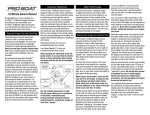
®
15
Dynamite .15S Water-Cooled
Engine
Instruction Manual
Thank you for purchasing the Dynamite .15S marine engine. We are
confident that you will enjoy many hours of exciting R/C boating
action with this engine as your power plant. Please read the
instructions carefully in order to get the most out of your
Dynamite Engine.
Water-Cooled
Because your Dynamite .15S engine is water-cooled, make sure
that you do not run the engine for an extended period of time outside of the water. Also, continually monitor the water-outlet while
operating to make sure that the water continues to circulate
through the cylinder head. If the tubing gets clogged or for some
other reason prohibits the water from circulating through the
cylinder head, the engine will overheat and fail. This could cause
permanent damage to the engine. It is very important that you
properly hookup the water pickup line to the engine to provide
the necessary cooling.
Double Taper Piston/Sleeve
Your Dynamite .15S Engine features a double-taper piston and
sleeve. Each piston and sleeve is hand matched. Replacement
piston and sleeves are sold as a set since you never want to
replace just the piston or the sleeve individually.
Crankcase Porting
Your Dynamite .15 Engine has a third port that is machined into
the crankcase to significantly enhance the intake flow, resulting in
more horsepower.
Crankshaft Balancing
The .15S provides a well-balanced crankshaft, which offers a
smoother running and more efficient engine and will help create
more horsepower and reliability.
Section 1: Using the Proper Fuel and Glow Plug
To achieve reliability and proper tuning of any 2-cycle model
engine, it is highly recommended that you use fuel and glow
plugs that are specially designed for these types of engines.
Do not use any type of airplane glow fuel. We recommend using
Blue ThunderTM First Run Break-In Fuel for the first six tanks of
running. This fuel will ensure maximum life of your new and/or
rebuilt engine. After proper break-in, switch to Blue Thunder
regular fuel or Blue Thunder Race Formula blend. These fuels are
vigorously researched and specifically formulated for excellent
power and engine protection. Blue Thunder—the #1 car fuel
in America!
The Dynamite MC-59 McCoy Power Plugs (DYN2508) will provide
the best performance and longevity for your engine.
Section 2: Pro Mix Carburetor
Your .15S comes equipped
with the Dynamite Pro Mix
Carburetor. Each Pro Mix
Carburetor is preadjusted
to make starting easier.
This setting should give
you a "rich" mixture of
fuel to your engine. This
setting is approximately
2 turns open for the highspeed and 7 turns open
for the low-speed needle.
Richer
When the engine starts, the muffler should emit excessive
white/blue smoke, and the engine should be rich to such an extent
that it is not providing horsepower or idling smoothly.
During the first tank of fuel, advance the idle via the idle adjustment screw more than normal to prevent stalling at idle due to the
rich fuel mixture for break-in.
High-Speed
Needle
Valve
For the break-in period, we recommend a slightly rich low-speed
needle setting and a very rich high-speed needle setting for the
first few tanks. Again, if the engine does not start after several
tries, refer to the Troubleshooting Guide or call the Horizon
Service Center at (217) 355-9511.
Idle
Adjustment
Screw
Higher
Idle
does not start, refer to the Troubleshooting Guide in the manual.
You may have to "blip" the throttle on the transmitter (applying
throttle on/off) while trying to start the engine. New engines are
harder to start because of the tight piston/sleeve fit. Never start
an engine to full throttle. Over-revving an engine will cause premature wear and breakage.
Low-Speed
Needle
Valve
Leaner
If you have difficulty
starting your engine,
check the factory setting. When checking the number of turns the
high-speed needle is open, screw the needle clockwise (leans out
the fuel mixture) using a straight tip Tuning Screwdriver
(DYN2775) and count the number of complete revolutions of the
needle until it stops turning. (Do not tighten down on the needle
valve.) Then unscrew the needle valve (counterclockwise, giving
more fuel to the engine) 2 turns before attempting to start the
engine again.
When checking the low-speed needle, it is critical that the
throttle barrel is closed when screwing in the low-speed needle
and that you don’t over-tighten the needle. Use the same procedure above for checking the low-speed needle.
Section 3: Breaking in Your Engine
The first start-up of your engine is the most critical moment of
your engine’s life, dictating how it will perform from that time
forward. Turn on the radio system and attach a glow driver
(DYN1925-DYN1950) to the glow plug. Start the engine with the
pull starter that is included on your engine.
Note: When using the pull-start of your engine, never pull the
rope out to its full length, as doing so may cause damage and
the rope may not retract. Quick, short pulls of the starter rope
are the best technique to use with the pull starter.
If the pull starter is very hard to pull (i.e., it will not extend out of
the pull starter assembly), the engine may be hydro-locked.
Excessive fuel between the head and piston will not let the piston
travel to TDC (Top Dead Center). Loosen the plug one turn and try
to start the engine. If the engine starts, retighten the plug with
the attached glow driver while the engine is running. If the engine
After you get the engine started, drive your boat around varying
the throttle of your transmitter on and off through one tank of
fuel, making sure that the engine is rich. Make sure that you do
not travel too far from shore at this time, as it may be necessary to retrieve it if the engine dies.
After two or three tanks of fuel, start leaning out the high-speed
needle 1/16" at a time. It generally takes about five to six tanks
before you want to lean out the engine until it supplies good
power. Do not skip this process of breaking in the engine.
If you do not follow this procedure, you could cause damage to
your engine.
Remember, be patient during your first start-ups and runs. With a
high-performance engine like the .15S, first run attempts can take
some time. Once you are through the break-in process, your
patience will be rewarded. You will have an engine that is easier to
start, tunes more consistently, and has more power.
Note: It is common for an ABC engine to go through a glow plug
or two during break-in. To test the plug, let the engine idle at a
properly adjusted low-speed needle setting with the glow driver
on. Then remove the glow driver. If the plug is good, you will not
hear a rpm change in the engine. If the engine loads up and the
rpm falls off, the glow plug will need to be replaced.
Section 4: Setting the Needle Valves
When adjusting the needle valves for maximum performance,
adjust the needles in small increments, just 1/8 of a full turn at
a time.
The worst thing you can do is to run the engine too lean—doing so
shortens the reliability of the engine. When the engine is set too
lean, it will run strong at first but will then sag, hesitate, or stall
when accelerating.
Tuning the High-Speed Needle
To check the high-speed needle, start the engine and run the boat
in the water for 1-2 minutes. Then bring the boat back in shore.
Place a few drops of water on the head. If the water immediately
evaporates, the setting is too lean. If it takes about 3-5 seconds
before the water evaporates, the settings are correct. If the water
stays on the head longer than 5 seconds without evaporating, set
the boat back in the water and run it for an additional 1-2 minutes.
If you repeat this procedure and the water is still not evaporating
within 3-5 seconds, the setting is too rich. To lean out the engine,
simply turn the high-speed needle clockwise 1/8 of a turn and run
the engine again. Continue doing this until the high-speed needle is
set correctly.
Tuning the Low-Speed Needle
It is best to tune the low-speed needle after setting the high-speed
needle. When you have achieved the proper operating temperature,
idle the engine and pinch the fuel line with you fingers at the fuel
inlet nipple of the carburetor. If the engine dies immediately, the
low end is set too lean. When you pinch the fuel line, the rpm
should increase for about 4 seconds, and then the engine should
die. To achieve the correct setting, always adjust the needle only
1/16 of a full turn, then test it before continuing.
After you have attained the correct needle settings, the engine will
have a strong sounding, high-pitched whine at full speed. A thin
trail of whitish smoke will be seen coming from the exhaust.
Idle Adjustment
The last setting on your engine is the idle screw. To obtain a higher
idle, turn the idle screw clockwise; for lower idle, turn the idle screw
counterclockwise.
Section 5: Engine Maintenance
To ensure that your engine maintains its high performance and reliability, periodic maintenance must be performed. After each day’s
use of the engine, it is important to use a high-quality "after run"
oil or fuel in the engine.
The methanol used in the fuel draws moisture that can cause
corrosion inside the engine. We highly recommend Blue ThunderTM
Final Run (DYN2255) as it is formulated specifically for protecting
your engine when it is not in use.
Follow these steps after each day’s use of the engine.
• Empty all excess fuel from the fuel tank
• Use Final Run Fuel following the Final Run instructions
• Clean and inspect the outside of the engine
Changing the Rod
With the rod having most of the stress of any other part of a
2-cycle engine, it is important to replace the rod after every
2 gallons of fuel that has been run through the engine. This is a
safe time frame for replacing the rod as it is less expensive to
install a new rod than taking the chance of having it break and
damage the engine. To replace the rod, refer to the line drawing
on the back of the manual. Study the drawing carefully and pay
close attention when removing the piston , sleeve, and rod. They
must be installed exactly in their original position in order to avoid
damaging your engine. If you have any questions about this procedure, please see your local hobby retailer or contact the Horizon
Service Center.
Section 6: Troubleshooting Guide
PROBLEM
POSSIBLE SOLUTION
Engine won’t start
Reset needles to the factory setting
Improper needle setting
Out of fuel
Improper fuel
Improper glow plug
Glow starter not charged
Dead glow plug
Engine flooded
Engine starts,
then dies
Engine runs
for partial tank,
then dies
Pressure line blocked or unhooked
Reset needles to baseline setting
Improper needle settings
Bad glow plug
Idle speed set too low
Improper needle settings
Overheated engine
Glow plug failed due to lean engine
setting
Section 7: Replacing the Pull Starter
If you need to replace the pull starter of your .15S, remove the
three screws from the pull starter case. Be very careful when
taking the pull starter case off of the engine and make sure the
recoil spring does not dislodge from the unit. The recoil spring is
very difficult to wind back onto the rope pulley and install back
into the pull starter case. In most cases, it is easier to have a
replacement Recoil Spring in your pit box (DYN6542) or Pull
Starter unit (DYN6535), which includes the recoil spring, rope/pulley, and pull starter housing. For other replacement parts for the
pull starter and disassembling guidance, refer to the line drawing in
the manual. When reassembling the pull starter, be absolutely sure
that each part is oriented in the correct manner.
• Damage due to improper disassembly or re-assembly
• Modification of any kind
• Normal engine wear
If your engine is in need of repair, please follow these steps:
1. Ship your engine in its original box (packaged in a sturdy box)
freight prepaid to:
Horizon Service Center
ATTN: Dynamite Service
4105 Fieldstone Rd.
Champaign, IL 61822
(217) 355-9511
2. Include a note containing a brief summary of the difficulty you
are experiencing and include the following information:
• Nitro content and brand of fuel
• Type of glow plug used
• Type of air filter used
• Approximately how much running time the engine had before
experiencing difficulty
Please date your correspondence and be sure your name and
address appear on this enclosure. Also include a daytime phone
number.
3. Warranty Repair: To receive warranty service, you must include
your original dated sales receipt to verify proof-of-purchase
date. Providing warranty conditions have been met, your engine
will be repaired free of charge.
4. Non-Warranty Repairs: Should your repair cost exceed $50.00,
you will be provided with an estimate advising you of your
options. Any return freight for non-warranty repairs will be billed
to you.
5. Payment Method: Please advise the Horizon Service Center of
the payment method you prefer to use. Please specify Visa or
MasterCard, or you may mail in a money order with the correct
total when repairs are completed. If you prefer to use your credit card, please include your card number and expiration date.
DYN6502
DYN6520
DYN6522
DYN6523
DYN6524
DYN6529
DYN6530
DYN6531
DYN6532
DYN6535
DYN6536
DYN6537
DYN6538
DYN6539
DYN6540
DYN6541
DYN6542
DYN6543
DYN6550
DYN6551
DYN6552
DYN6553
DYN6554
DYN6555
DYN6556
DYN6557
DYN6558
DYN6559
DYN6560
DYN6561
DYN6562
DYN6565
DYN6571
DYN6572
DYN6573
DYN6574
DYN6575
DYN6576
.15S Water-Cooled, Universal
139.95
Connecting Rod: 12S, 12SPD, 15S
19.95
Head Shims, .01, .02: 12SPD, 15S
3.95
Screw Set: 12S, 12SPD, w/o PS (8), 15S
3.95
PS Uni-Crankshaft: 12S, SPD, 15S
19.95
Flywheel Hub: 12S, 12SPD, 15S
1.95
Crankshaft Nut: 12S, 12SPD, 15S
1.95
Front Sealed Bearing: 12S, 12SPD, 15S
6.95
Rear Bearing: 12S, 12SPD, 15S
8.95
Pull Starter: 12S, 12SPD, 15S
19.95
PS Backplate: 12S, 12SPD, 15S
6.95
PS One-Way Bearing, 15S
12.95
PS Shaft: 12S, 12SPD, 15S
2.95
PS Cushion Spring: 12S, 12SPD, 15S
1.95
PS Screw Set: 12S, 12SPD, 15S
2.95
PS Handle w/Cotter & Extension: 12S, 12SPD, 15S 3.95
PS Recoil Spring: 12S, 12SPD, 15S
4.95
PS Rope/Pully: 12S, 12SPD, 15S
2.95
Carburetor: 12S, 12SPD, 15S
24.95
Carburetor Body w/Spray Bar: 12S, 12SPD, 15S 12.95
Throttle Barrel: 12S, 12SPD, 15S
5.95
Throttle Barrel Boot: 12S, 12SPD, 15S
2.95
Throttle Arm w/Nut: 12S, 12SPD, 15S
2.95
High Speed Needle Valve: 12S, 12SPD, 15S 4.95
High Speed Needle Holder: 12S, 12SPD, 15S
4.95
High Speed Assembly Washers: 12S, 12SPD, 15S 2.95
Fuel Inlet Nipple: 12S, 12SPD, 15S
2.95
Low Speed Needle Valve: 12S, 12SPD, 15S 4.95
Idle Screw w/Spring: 12S, 12SPD, 15S
2.95
Carburetor Cinch Bolt: 12S, 12SPD, 15S
3.95
Throttle Barrel Spring: 12S, 12SPD, 15S
1.95
O-Ring Set, Complete: 12S, 12SPD, 15S
2.95
Water-Cooled Head: 15S
15.95
Piston Pin w/2 Clips: 15S
2.95
Combustion Chamber: 15S
5.95
Crankcase: 15S
18.95
O Ring Set: Water-Cooled Head
3.95
Piston/Cylinder Set: 15S
34.95
DYN6523 (4)
DYN6571
DYN6575
DYN6522
DYN6573
DYN6576
DYN6572
DYN6520
DYN6550
DYN6565
DYN6574
DYN6529
DYN6530
DYN6531
DYN6561
DYN6532
DYN6524
DYN6565
DYN6555
DYN6565
DYN6556
Section 8: Warranty
Dynamite’s engines are guaranteed against workmanship and
manufacturing defects for period of 2 years from the original date
of purchase. This engine is of excellent design and materials and
will provide many hours of modeling enjoyment If properly cared
for, this engine is extremely durable. However, if normal common
sense care is not given to your engine, it will not function properly
for as long as intended. The following items can shorten its life and
will not be covered under warranty:
• Damage due to insufficient maintenance
• Damage related to over-revving the engine
• Rusted bearings
• Crash related damage
• Damage due to use of improper fuel and/or glow plug
• Damage due to lean runs
• Damage caused by foreign objects such as dirt or broken glow
plug elements
• Damage caused by unreasonable mounting or running conditions
Parts Listing:
Richer
DYN6557
DYN6558
DYN6535
Ldle
Adjustment
Screw
DYN6560
DYN6551
Higher
Idle
Low-Speed
Needle
Valve
Leaner
DYN6562
DYN6552
DYN6565
High-Speed
Needle
Valve
DYN6553
DYN6565
DYN6559
DYN6554
DYN6537
DYN6565
DYN6536
DYN6540
DYN6538
DYN6539
DYN6543
DYN6542
DYN6535
DYN6540
DYN6541