1
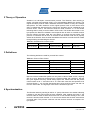
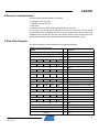
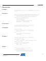
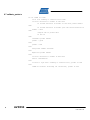
AVR350: Xmodem CRC Receive Utility for AVR®
Features
•
•
•
•
•
•
•
•
Programmable Baud Rate
Half Duplex
128-byte Data Packets
CRC Data Verification
Framing Error Detection
OverRun Detection
Less than 1K Bytes of Code Space
C High-level Language Code
8-bit
Microcontrollers
Application Note
1 Introduction
The Xmodem protocol was created years ago as a simple means of having two
computers talk to each other. With its half-duplex mode of operation, 128-byte
packets, ACK/NACK responses and CRC data checking, the Xmodem protocol has
found its way into many applications. In fact most communication packages found
in the PC today have a Xmodem protocol available to the user.
Rev. 1472D-AVR-01/08
2 Theory of Operation
Xmodem is a half-duplex communication protocol. The Receiver, after receiving a
packet, will either acknowledge (ACK) or not acknowledge (NACK) the packet. The
original Xmodem protocol used a standard checksum method to verify the 128-byte
data packet. The CRC extension to the original protocol uses a more robust 16-bit
CRC to validate the data block and is used here. Xmodem can be considered to be
receiver driven. That is, the Receiver sends an initial character “C” to the sender
indicating that it’s ready to receive data in CRC mode. The Sender then sends a 133byte packet, the Receiver validates it and responds with an ACK or a NACK at which
time the sender will either send the next packet or re-send the last packet. This
process is continued until an EOT is received at the Receiver side and is properly
ACKed to the Sender. After the initial handshake the receiver controls the flow of data
through ACKing and NACKing the Sender.
Table 2-1. XmodemCRC Packet Format
Byte 1
Byte 2
Byte 3
Bytes 4 - 131
Bytes 132 - 133
Start of Header
Packet Number
~(Packet Number)
Packet Data
16 bit CRC
3 Definitions
The following defines are used for protocol flow control.
Table 3-1. Protocol Flow Control
Symbol
Description
Value
SOH
Start of Header
0x01
EOT
End of Transmission
0x04
ACK
Acknowledge
0x06
NACK
Not Acknowledge
0x15
C
ASCII “C”
0x43
Byte one of the XmodemCRC packet can only have a value of SOH or EOT, anything
else is an error. Bytes two and three form a packet number with checksum, add the
two bytes together and they should always equal 0xff. Please note that the packet
number starts out at “1” and rolls over to “0” if there are more than 255 packets to be
received. Bytes 4 - 131 form the data packet and can be anything. Bytes 132 and 133
form the 16-bit CRC. The high byte of the CRC is located in byte 132.
4 Synchronization
The Receiver starts by sending an ASCII “C” (0x43) character to the sender indicating
it wishes to use the CRC method of block validating. After sending the initial “C” the
receiver waits for either a three second time out or until a buffer full flag is set. If the
receiver is timed out then another “C” is sent to the sender and the three second time
out starts again. This process continues until the receiver receives a complete 133byte packet.
2
AVR350
1472D-AVR-01/08
AVR350
5 Receiver Considerations
This protocol NACKs the following conditions:
1. Framing error on any byte
2. OverRun error on any byte
3. CRC error
4. Receiver timed out (didn't receive packet within one second)
On any NACK, the sender will re-transmit the last packet. Items one and two should
be considered serious hardware failures. Verify that sender and receiver are using the
samebaud rate, start bits and stop bits. Item three is found in noisy environments, and
the last issue should be self-correcting after the receiver NACKs the sender.
6 Data Flow Diagram
The data flow diagram below simulates a 5-packet file being sent.
Table 6-1. Data Flow Diagram
Sender
Receiver
<---
“C”
<---
“C”
--->
Packet OK
<---
ACK
--->
(Line Hit during Data Transmission)
<---
NACK
Times Out after Three Seconds
SOH
SOH
SOH
0x01
0x02
0x02
SOH
0x03
SOH
0x03
0xFE
0xFD
0xFD
0xFC
Data
Data
Data
Data
CRC
CRC
CRC
--->
Packet OK
<---
ACK
CRC
--->
Packet OK
<---
ACK
CRC
--->
Duplicate Packet
<---
ACK
(ACK Gets Garbled)
SOH
0x04
0xFC
0xFB
Data
Data
CRC
SOH
0x04
0xFB
Data
CRC
SOH
0x05
0xFA
Data
CRC
SOH
0x05
0xFA
Data
CRC
--->
(UART Framing Error on Any Byte)
<---
NACK
--->
Packet OK
<---
ACK
--->
(UART Overrun Error on Any Byte)
<---
NACK
--->
Packet OK
<---
ACK
EOT
--->
Packet OK
(ACK Gets Garbled)
<---
ACK
EOT
--->
Packet OK
Finished
<---
ACK
3
1472D-AVR-01/08
7 Modifications to Receive Protocol
Users may wish to count how many “C’s” were sent during synchronization and after
“n” number of tries abort the receive attempt. For embedded applications it’s not
mandatory to have a 128-byte packet. You could have 64, 32, or even a 16-byte
packet. The sender of course would have to comprehend this.
If users do not wish to use the CRC method of data verification, simply replace
sending a “C” for synchronization with a NACK instead. The sender will then send
only the simple checksum of the data packet. Of course, the buffer size decreases by
one and data errors may occur. This modification would allow communication with
equipment that supports only the checksum method of data verification.
8 Software
Routines were compiled using IAR Workbench version 4.11A with high optimization.
The software was tested using Hyperterminal at baud rates up to 115.2K. The
receiver expects 8 start bits, 1 stop bit, and no parity bits.
The STK500 starter kit is used as a test platform for an ATmega88 running from its
calibrated 8MHz internal RC oscillator. This is sufficiently accurate at room
temperature for operation up to 38.4K Baud. For higher Baud rates the on-board
3.6864MHz oscillator or a 7.3728 MHz crystal should be used, with the init routine
modified to properly set up the UART baud rate register UBRR0. Wait loops in the
sendc and the recv_wait routines would also need modification.
To verify proper operation of this code on the STK500, connect:
• PD0 to ‘RS232 SPARE’ RXD.
• PD1 to ‘RS232 SPARE’ TXD.
• PD2 to switch SW0.
Refer to the STK500 user manual for jumper locations and definitions. Connect a 9pin serial cable from a PC to the STK500 “RS232 SPARE” port, turn on power and
use SW0 as a start of reception signal. Use an ATmega48/88/168 fitted to socket
SCKT3200A2 to execute the code.
Table 8-1. Protocol Flow Control
4
Name
Size in Bytes
Function
calcrc
46
Calculates 16-bit CRC
init
36
Low-level Hardware Initialisation
purge
50
Reads UART Data Register for One Second
receive
52
Main Receive Routine
recv_wait
46
Waits until Buffer Full Flag is Set or One
Second Timeout
respond
56
Sends an ACK or a NACK to the Sender
sendc
100
Sends an ASCII “C” Character to the Sender
until the Buffer Full Flag is Set
timer1
14
Timer1 Interrupt
uart
96
Uart Receive Interrupt
validate_packet
136
Validates Senders Packet
xmodem
42
Main
AVR350
1472D-AVR-01/08
AVR350
9 Pseudo-Code
9.1 purge.c
initialize timer1 counter for a 1 second delay read uart for 1
second
9.2 receive.c
send a ’C’ character to sender until receive buffer is full
validate received packet send an ACK or a NACK to sender
if packet was bad then wait for new good packet
while not end of transmission
wait for buffer to fill
validate the packet
Act on data received or monitor errors
send an ACK or a NACK to sender
9.3 recv_wait.c
initialize timer1 counter for a 1 second delay
wait till buffer is full or timeout
9.4 respond.c
clear error flags
If packet was good or end of transmission then
Send an ACK
Else
Purge senders uart transmit buffer
Send a NACK
9.5 sendc.c
initialize timer1 counter for a 3 second delay
clear error flags
while buffer is not full
send ’C’ character to sender, signaling CRC mode
enable timer counter
wait for buffer full or timeout
if timed out clear error flags
restart timer
9.6 uart.c
check uart for framing or overrun errors
read byte from uart
verify first byte in receive buffer is valid
if buffer is full set buffer full flag
5
1472D-AVR-01/08
9.7 validate_packet.c
if not timed out then
if no uart framing or overrun errors then
if first character in buffer is SOH then
if second character in buffer is the next packet number
then
if second character in buffer plus the third character in
buffer = 0xff
then
compute CRC on packet data
if CRC ok
then
increment packet number
packet = good
else
packet = bad
else
bad packet number checksum
else
duplicate packet number
else
if first character in buffer is EOT then
end of transmission
else
at least 1 byte had a framing or overrun error, packet is bad
else
timed-out without receiving all characters, packet is bad
6
AVR350
1472D-AVR-01/08
Disclaimer
Headquarters
International
Atmel Corporation
2325 Orchard Parkway
San Jose, CA 95131
USA
Tel: 1(408) 441-0311
Fax: 1(408) 487-2600
Atmel Asia
Room 1219
Chinachem Golden Plaza
77 Mody Road Tsimshatsui
East Kowloon
Hong Kong
Tel: (852) 2721-9778
Fax: (852) 2722-1369
Atmel Europe
Le Krebs
8, Rue Jean-Pierre Timbaud
BP 309
78054 Saint-Quentin-enYvelines Cedex
France
Tel: (33) 1-30-60-70-00
Fax: (33) 1-30-60-71-11
Atmel Japan
9F, Tonetsu Shinkawa Bldg.
1-24-8 Shinkawa
Chuo-ku, Tokyo 104-0033
Japan
Tel: (81) 3-3523-3551
Fax: (81) 3-3523-7581
Technical Support
[email protected]
Sales Contact
www.atmel.com/contacts
Product Contact
Web Site
www.atmel.com
Literature Request
www.atmel.com/literature
Disclaimer: The information in this document is provided in connection with Atmel products. No license, express or implied, by estoppel or otherwise, to any
intellectual property right is granted by this document or in connection with the sale of Atmel products. EXCEPT AS SET FORTH IN ATMEL’S TERMS AND
CONDITIONS OF SALE LOCATED ON ATMEL’S WEB SITE, ATMEL ASSUMES NO LIABILITY WHATSOEVER AND DISCLAIMS ANY EXPRESS, IMPLIED
OR STATUTORY WARRANTY RELATING TO ITS PRODUCTS INCLUDING, BUT NOT LIMITED TO, THE IMPLIED WARRANTY OF MERCHANTABILITY,
FITNESS FOR A PARTICULAR PURPOSE, OR NON-INFRINGEMENT. IN NO EVENT SHALL ATMEL BE LIABLE FOR ANY DIRECT, INDIRECT,
CONSEQUENTIAL, PUNITIVE, SPECIAL OR INCIDENTAL DAMAGES (INCLUDING, WITHOUT LIMITATION, DAMAGES FOR LOSS OF PROFITS,
BUSINESS INTERRUPTION, OR LOSS OF INFORMATION) ARISING OUT OF THE USE OR INABILITY TO USE THIS DOCUMENT, EVEN IF ATMEL HAS
BEEN ADVISED OF THE POSSIBILITY OF SUCH DAMAGES. Atmel makes no representations or warranties with respect to the accuracy or completeness of the
contents of this document and reserves the right to make changes to specifications and product descriptions at any time without notice. Atmel does not make any
commitment to update the information contained herein. Unless specifically provided otherwise, Atmel products are not suitable for, and shall not be used in,
automotive applications. Atmel’s products are not intended, authorized, or warranted for use as components in applications intended to support or sustain life.
© 2008 Atmel Corporation. All rights reserved. Atmel®, logo and combinations thereof, AVR® and others, are the registered trademarks or
trademarks of Atmel Corporation or its subsidiaries. Other terms and product names may be trademarks of others.
1472D-AVR-01/08