1
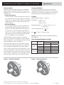
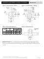
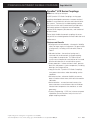
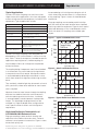
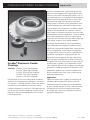
DYNAFLEX ELASTOMERIC FLEXIBLE COUPLINGS
Page 87 of 124
Powertrain component life is determined by the load
spectrum each component will experience during the
machine’s service life. Reciprocating engines, such as
spark-ignited gasoline and compression-ignited diesels,
produce alternating torque loads which, when superimposed on the steady driving torque, create alternating stresses in driveline system components which
shorten component life and reliability. High transient
start-up torques and misalignment caused by skewed
rotational axes between driver and driven in electric
motor, hydraulic and pneumatic drives also cause high
imposed forces on driven components. These unwanted
forces loosen bolted joints and cause spline fretting,
clutch disk wear, bearing failure, gear tooth fatigue and
shaft fatigue, among an array of other problems.
Elastomeric flexible couplings solve these problems.
They prolong driveline component life because they
reduce the magnitude of imposed loads, attenuate vibration in multiple planes, accommodate misalignments
in multiple planes, and act as barriers impeding noise
created by meshing gears, engaging clutches, etc.
Dynaflex® Elastomeric Flexible
Couplings
Featuring: Dynaflex® Shear-Type Couplings
Dynaflex® Spool-Type Couplings
Dynaflex® Bushing-Type Couplings
Dynaflex® LCR Series Couplings
Dynaflex® LCD Series Couplings
Efficient power transmission and driveline component
durability are among powertrain designers’ most important concerns. Increased durability and up-time are two
characteristics demanded by purchasers of today’s
complex and expensive machinery. These demands can
only be met with reliable, trouble-free, smooth-running
powertrains free from damaging loads which compromise component life.
Elastomeric flexible couplings are also maintenancefree. They require no lubrication or other maintenance
throughout their service life. Among the large variety of
coupling types available, LORD Corporation’s elastomeric couplings offer the most comprehensive package
of benefits available to the powertrain designer. LORD
Corporation’s product lines include five different elastomeric coupling styles which cover a wide range of
application requirements.
Application
Application requirements suggest the coupling style
needed to optimize powertrain performance and
component longevity. Misalignment accommodation,
torsional vibration isolation, transient shock dissipation
and required service life are important parameters
to consider when selecting a coupling to fill specific
application requirements.
A part’s listing in this catalog does not guarantee its availability.
To download/print the most current catalog, go to www.lordfulfillment.com/upload/PC7000.pdf.
Rev.1 10/08
DYNAFLEX ELASTOMERIC FLEXIBLE COUPLINGS
LORD engineers can assist you with selecting an appropriate coupling type and configuration. With extensive
analytical capability and years of experience in designing
products for powertrain vibration, shock and motion
control, LORD engineers offer everything from simple
application assistance to complex system analysis and
specialized product design.
Torsional vibration, transient shock and misalignment
load analyses require specialized computer programs
and engineering experience. LORD engineers can
analyze your system and recommend the right solution,
whether it’s a selection from the standard product line or
a custom design.
LORD Corporation’s standard product lines of elastomeric flexible powertrain couplings are presented in the
following sections. Many variations of standard products
are available, but not listed as ‘standard.’ Main drive, fan
drive, PTO and accessory drive couplings are available
in a host of custom designs and variations of standard
products. LORD engineers are ready to help you meet
your specific application requirements with custom
designs where necessary.
Product Lines
LORD offers five major lines of elastomeric flexible
couplings. Standard lines are presented on the following
pages. In addition to the standards listed, many
variations are available in each product line.
Dynaflex® Shear-Type Couplings
LORD Dynaflex Shear-Type Coupling features a durable
elastomeric flexing element bonded between two hubs.
These couplings are designed for fractional horsepower
applications requiring smooth starting transition, torsional
vibration isolation and misalignment accommodation.
Typical applications are small electric motor drives,
low-torque mechanisms, power take-offs and auxiliary
equipment drives.
Dynaflex® Spool-Type Couplings
LORD Dynaflex Spool-Type Couplings can be arranged
in a variety of configurations to create a wide range
of torque-transmitting capability. Elastomeric spool
elements can be purchased in lot sizes for customerassembled coupling designs, or LORD can provide a
complete coupling assembly to meet specific application
requirements. Typical applications are large drives
requiring high torque capacity and low torsional stiffness.
Page 88 of 124
Dynaflex® Bushing-Type Couplings
LORD Dynaflex Bushing-Type Couplings are bonded
elastomeric elements designed for use in multiple
element coupling configurations where high torque
capacity is required. Bushings are available in a
variety of stiffnesses. They can be purchased in lots for
customer-assembled designs, or LORD can provide
complete coupling assemblies designed to meet your
specific application requirements. Applications requiring
high torque/high torsional stiffness, but angular, axial and
parallel misalignment accommodation can be designed
using these bushings in a variety of configurations
including parallel and series arrangements.
Dynaflex® LCR Series Couplings
LORD Dynaflex LCR Series Couplings features an
elastomeric ring with bonded, bush-type inserts allowing
various attachment configurations. These couplings
offer a soft torsional spring rate which permits smooth
transmission of driving torque while attenuating
shock torques and providing excellent misalignment
accommodation. These couplings are used in PTO
drives where torsion and cocking flexibility are required.
They can be mated with a variety of hub configurations.
Special high-torque designs are available, as well
as custom designs to meet special application
requirements.
Dynaflex® LCD Series Couplings
LORD Dynaflex LCD Series Couplings are the ultimate
coupling for reciprocating engine drives. This coupling
features a bonded elastomeric flexing element which is
radially precompressed into a flanged outer housing.
This design produces a low torsional stiffness for
maximum isolation of engine firing-pulse-induced
torsional disturbances, torque overload slip protection,
misalignment accommodation, superior shock pulse
attenuation and fatigue life, and is adaptable to a variety
of drive attachment designs. Custom designs are
available to fit nearly every SAE flywheel configuration
available from most engine manufacturers.
A part’s listing in this catalog does not guarantee its availability.
To download/print the most current catalog, go to www.lordfulfillment.com/upload/PC7000.pdf.
Rev.1 10/08
DYNAFLEX ELASTOMERIC FLEXIBLE COUPLINGS
Page 89 of 124
Coupling Application Guide
Dynaflex
Shear-Type
Dynaflex
Spool-Type
Dynaflex
Bushing-Type
Dynaflex
LCR Series
Dynaflex
LCD Series
Horsepower
Rated: 1/50 to 1
Rated: 50 to 1000
Rated: 10 to 600
Rated: 4 to 135
Rated: 75 to 2000
Best Application
Area
Low-frequency
vibration,
multidirectional
misalignment
Low-frequency vibration, high-power drive
systems
Multidirectional
misalignment, high
capacity
Large misalignment,
safetied drive
requirements
Diesel engines, lowfrequency vibration,
multidirectional
misalignment
Outstanding
Capabilities
Effectively
accommodates
combinations of
misalignment, high
torsional resilience
Versatility in design
for exact application
requirements
(stiffness and
capacity)
High torque capacity
versus size
Angular misalignment
capability
Fits many standard
flywheels, high
torsional
Versatility Factor
Widest application
potential of all
elastomeric couplings
Capacity and resilience can be varied
by changing number
and type of spool
Numerous
combinations possible
simply by changing
flexing elements
Torsional spring rate
varied by changing
modulus or wall
thickness
Large horsepower,
high horsepower
capacity
Easily incorporated
Easily incorporated
Inherent
Inherent
Slip-torque feature
Fail-Safe
Characteristics
Dynaflex Elastomeric Flexible Couplings
A part’s listing in this catalog does not guarantee its availability.
To download/print the most current catalog, go to www.lordfulfillment.com/upload/PC7000.pdf.
Rev.1 10/08
DYNAFLEX ELASTOMERIC FLEXIBLE COUPLINGS
A part’s listing in this catalog does not guarantee its availability.
To download/print the most current catalog, go to www.lordfulfillment.com/upload/PC7000.pdf.
Page 90 of 124
Rev.1 10/08
DYNAFLEX ELASTOMERIC FLEXIBLE COUPLINGS
Page 91 of 124
Typical applications include:
• Information Systems – Motor drive, printer rollers,
indexing devices, linear actuator, drives and card
sorters
• Hospital Bed – Actuator drive
• Dynamometer – Driveline
• Tachometer – Driveline
• Pumps, Blowers, Compressors – Driveline
Features and Benefits
Dynaflex® Shear-Type Couplings
Rated: 1/50 to 1 hp at 1750 rpm
LORD Dynaflex Shear-Type Couplings are compact,
one-piece flexible couplings economically constructed to
isolate low-frequency vibration and accommodate multidirectional misalignment.
These couplings reduce the adverse effects of transient
shock torques, torsional vibration, noise and misalignment associated with small equipment drivelines. This
results in longer service life, smoother, quieter operation,
less maintenance, and lower cost for your end product.
Shear-Type flexible couplings are useful in many small
equipment driveline applications. Multi-directional
misalignment capabilities make them ideally suited for
fractional horsepower drivelines demanding noise reduction, vibration isolation and maintenance-free operation.
• High torsional deflection
• Easy installation
• Versatile application potential - fractional horsepower
couplings are available in a range of sizes to permit
matching a specific coupling to your application.
• One-piece construction – convenient for small
equipment with fractional horsepower requirements.
Specified torque rating allows 15° angular deflection
for excellent vibration isolation.
• Multi-directional misalignment accommodation – elastomeric flexibility accommodates misalignments up to
1/32 inch parallel, 2° angular.
• Vibration isolation – low torsional stiffness is achieved
with the shear-type flexible coupling because
the rubber is loaded in shear. This allows for low
system natural frequencies and excellent driveline
disturbances.
• Shock protection – torsional shock loads are attenuated by torsional deflection of the elastomer. Torsional
flexibility smooths out rotational disturbances and
protects system components from early fatigue
failure.
• Noise reduction – no metal-to-metal contact; elastomeric barrier reduces gear noise, transmission and
motor hum between shifts.
• Maintenance-free – elastomer flexibility accommodates all motion without metal-to-metal wear, eliminates the need for lubrication.
• Long service life – Dynaflex Shear-Type Couplings
have proven themselves under demanding service
conditions. Elastomers resist effects of abrasive materials, oil and grease.
• Attachment – shear-type flexible couplings are available in an assortment of bore sizes. Refer to Table 1.
• Constant velocity – inherent design properties
produce a rotational constant velocity.
A part’s listing in this catalog does not guarantee its availability.
To download/print the most current catalog, go to www.lordfulfillment.com/upload/PC7000.pdf.
Rev.1 10/08
DYNAFLEX ELASTOMERIC FLEXIBLE COUPLINGS
Page 92 of 124
Dynaflex Shear-Type Couplings
Table 1 – Specifications and Dimensions
Coupling Part
Number
Standard Bore
Diameters
A (in)
C
(in)
D Ref.
(in)
E Ref.
(in)
F
(in)
HP at
1750 rpm
Ref.
Torque
Rating
(lb-in)
Static
Torsional
Stiffness
(lb-in/deg)
±20%
Set
Screw
Size
0.44
0.56
0.36
0.81
1/50
0.8
0.053
5/40
0.63
0.81
0.56
1.38
1/16
2.50
0.17
10/24
0.75
1.00
0.72
1.75
1/8
5
0.33
10/24
0.88
1.25
0.88
2.13
1/4
10
0.66
1/4-20
1.00
1.38
0.91
2.25
1/3
13
0.87
1/4-20
1.13
1.63
1.00
2.50
1/2
20
1.33
1/4-20
1.38
1.81
1.05
2.69
3/4
30
2.00
5/16-18
1.50
2.00
1.11
2.88
1
40
2.66
5/16-18
B (in)
SK-1947-6
0.125
0.125
SK-1947
0.187
0.187
SK-1947-19
0.187
0.250
SK-1947-29
0.250
0.250
J-1211-1-2
0.187
0.187
J-1211-1-1
0.250
0.250
J-1211-2-2
0.250
0.250
J-1211-2-11
0.250
0.312
J-1211-2-6
0.250
0.375
J-1211-2-3
0.312
0.312
J-1211-2-12
0.312
0.375
J-1211-2-1
0.375
0.375
J-1211-3-4
0.312
0.312
J-1211-3-14
0.312
0.375
J-1211-3-12
0.312
0.500
J-1211-3-2
0.375
0.375
J-1211-3-8
0.375
0.500
J-1211-3-1
0.500
0.500
J-1211-4-2
0.375
0.375
J-1211-4-35
0.375
0.500
J-1211-4-11
0.375
0.625
J 1211-4-14
0.500
0.500
J-1211-4-4
0.500
0.625
J-1211-4-1
0.625
0.625
J-1211-5-3
0.500
0.500
J-1211-5-4
0.500
0.750
J-1211-5-2
0.625
0.625
J-1211-5-1
0.750
0.750
J-1211-6-12
0.500
0.500
J-1211-6-18
0.625
0.625
J-1211-6-14
0.625
0.750
J-1211-7-16
0.500
0.750
J-1211-7-9
0.625
0.625
J-1211-7-3
1.00
1.00
Notes: Maximum recommended misalignment - 1/32 inch parallel, 2° angular.
Intrusion should not exceed “E” bore length dimensions.
Standard Construction: Hubs - steel; Bores - as listed; Set Screws - one per hub furnished but
not installed; Flexing Element - neoprene.
A part’s listing in this catalog does not guarantee its availability.
To download/print the most current catalog, go to www.lordfulfillment.com/upload/PC7000.pdf.
Rev.1 10/08
DYNAFLEX ELASTOMERIC FLEXIBLE COUPLINGS
Page 93 of 124
Figure 1 – Part Dimensions
Table 2 – Standard Bore Tolerances
Bore Sizes
Tolerance
from 0.000 to 0.499
+ 0.001 - 0.000
from 0.500 to 0.749
+ 0.0015 - 0.0000
from 0.750 to 1.499
+ 0.002 - 0.000
A part’s listing in this catalog does not guarantee its availability.
To download/print the most current catalog, go to www.lordfulfillment.com/upload/PC7000.pdf.
Rev.1 10/08
DYNAFLEX ELASTOMERIC FLEXIBLE COUPLINGS
A part’s listing in this catalog does not guarantee its availability.
To download/print the most current catalog, go to www.lordfulfillment.com/upload/PC7000.pdf.
Page 94 of 124
Rev.1 10/08
DYNAFLEX ELASTOMERIC FLEXIBLE COUPLINGS
Page 95 of 124
Dynaflex® Spool-Type Couplings
Rated: 5 to 1000 hp at 2000 rpm
LORD Dynaflex Spool-Type Couplings provide excellent
protection against destructive torsional vibration in hightorque drive systems.
These couplings are customer-assembled, using
bonded flexing spools from LORD, and bolted between
customer-supplied metal hubs. Spools should be placed
around recommended bolt circle on hub. Bonded
spools can be installed or replaced with minimum effort.
Coupling assembly has torsional deflection of 2° under
rated torque.
A part’s listing in this catalog does not guarantee its availability.
To download/print the most current catalog, go to www.lordfulfillment.com/upload/PC7000.pdf.
Rev.1 10/08
DYNAFLEX ELASTOMERIC FLEXIBLE COUPLINGS
Page 96 of 124
Dynaflex Spool-Type Couplings
Table 1 – Specifications and Dimensions
Spool Part
Number
Minimum Bolt Circle Diameter for Number of Mounts (in)
A
Diameter
B
Thickness
C
Thread
Attachement
3
4
5
6
J-4624-1
1.00
0.75
0.38
1/4-20-2A
1.20
1.42
1.70
2.00
2.30
2.62
2.92
J-3424-2
2.00
2.12
0.40
1/2-13-2B
2.30
2.82
3.40
4.00
4.60
5.22
5.84
6.46
7.50
7.72
J-5425-1
3.19
3.00
1.25
1/2-13-2A
3.62
4.41
5.30
6.25
7.18
8.18
9.12
10.20
11.00
12.10
J-5682-1
4.48
2.25
1.25
1/2-20-2A
5.10
6.20
7.45
8.75
10.10
11.50
12.80
14.30
15.70
17.00
7
8
9
10
11
12
3.24
3.56
3.86
It is suggested that all designs for Spool-Type Flexible Couplings be reviewed with
LORD Corporation.
Notes: Maximum recommended misalignment - 1/32 inch parallel, 1° angular.
Coupling permits wide latitude in shaft lengths. However, sufficient spacing between
shaft ends should be provided to allow for shaft end play.
Construction: Rubber elements - LORD does not supply hubs, elements only;
Metal parts - steel; Flexing element - environmental-resistant elastomer.
Bolt Circle Diameter (in)
Table 2 – Coupling Configuration Capacity Chart
Torque (lb-in x 100)
A part’s listing in this catalog does not guarantee its availability.
To download/print the most current catalog, go to www.lordfulfillment.com/upload/PC7000.pdf.
Rev.1 10/08
DYNAFLEX ELASTOMERIC FLEXIBLE COUPLINGS
Page 97 of 124
Figure 1 – Part Dimensions - J-4624-1
Figure 2 – Part Dimensions - J-3424-2
Figure 3 – Part Dimensions - J-5425-1
Figure 4 – Part Dimensions - J-5682-1
Figure 5 – Typical Assembly with Bonded Flexing Spools
A part’s listing in this catalog does not guarantee its availability.
To download/print the most current catalog, go to www.lordfulfillment.com/upload/PC7000.pdf.
Rev.1 10/08
DYNAFLEX ELASTOMERIC FLEXIBLE COUPLINGS
A part’s listing in this catalog does not guarantee its availability.
To download/print the most current catalog, go to www.lordfulfillment.com/upload/PC7000.pdf.
Page 98 of 124
Rev.1 10/08
DYNAFLEX ELASTOMERIC FLEXIBLE COUPLINGS
Page 99 of 124
Dynaflex® Bushing-Type Couplings
Rated: 10 to 600 hp at 2000 rpm
LORD Dynaflex Bushing-Type Couplings accommodate misalignment, cushion torsional shock, and do not
generate or transmit noise. Since relative motion is taken
in the elastomer rather than sliding metal surfaces, no
lubricant is involved or ever required. Dirt and grit cannot
effect the coupling bushings. The elastomer has been
compounded to provide long service life.
Typical applications include driveline installations where
multi-directional misalignment must be accommodated
and torque loads are medium to high.
Specification, selection and dimension information
provided on the following pages facilitate design of the
coupling assembly. The bushings are standard parts,
and the flanges can be supplied by the end user or by
LORD as a special design.
A part’s listing in this catalog does not guarantee its availability.
To download/print the most current catalog, go to www.lordfulfillment.com/upload/PC7000.pdf.
Rev.1 10/08
DYNAFLEX ELASTOMERIC FLEXIBLE COUPLINGS
Page 100 of 124
Selection Guide
Torsional Flexibility
Compression bushing-type couplings are assembled
by pressing the elastomeric bushings into sockets of a
coupling flange. Once assembled, the coupling can be
used two ways:
• Parallel Arrangement
The driving shaft can be connected to all of the bushings, and the driven shaft connected to the coupling
flange. This arrangement loads all bushings in parallel
and produces maximum torque capacity and a less
resilient coupling.
• Series Arrangement
This arrangement requires an even number of bushings per flange. Mating flanges of the driving and
driven shafts are attached to alternate bushings. This
arrangement transmits the torque through the bushings in an N x N series arrangement, thereby making
the torque capacity one-half of the parallel arrangement. The coupling is also more flexible.
Bushing-type couplings are relatively stiff torsionally
compared to other elastomeric couplings. The torsional
spring rate of a coupling assembly can be calculated by
using the equation and data provided on the curves.
When high torque and small space are the controlling factors, the parallel arrangement is recommended.
When misalignment is the controlling factor, the bushings
should be applied in series arrangement.
Table 1 provides selection criteria for parallel arrangement, Table 2 provides data for the series arrangement.
Bushing selection is dependent upon torque requirements, angular, parallel and axial misalignments, as well
as bolt circle diameter, number of bushings and bushing
size. The torque values shown on the charts are nominal.
The bushings are capable of withstanding higher torques
due to the shock loads or other short duration surges.
Figure 1 – Parallel Arrangement
Example
Required torque capacity – 3400 lb-in
Misalignment – Angular – 1.75°
Axial – 1/8 in
Parallel – 1/32 in
Proposed Coupling – 7 x 7 Series, J-5737-1, (N = 7)
8 in bolt circle
Torsional Spring Rate, Kθ = N R2 KR
2
Kθ = 7 (4)2 4000 = 224,000 lb-in/rad.
2
Caution: Shaft length must be considered for potential
whirl problems.
Recommended Misalignment Limits
Misalignment
Angular
Single
Coupling
Double
Coupling
Bushing Arrangement
Parellel
Series
1°
1.75°
Parallel
1/64 in
1/32 in
Axial
±1/16 in
±1/8 in
Angular
2°
3.5°
Parallel
3/16 to 1/2 in*
3/8 to 1 in*
Axial
±1/8 in
±1/4 in
* Dependent on shaft length (10 to 30 in).
Figure 2 – Series Arrangement
A part’s listing in this catalog does not guarantee its availability.
To download/print the most current catalog, go to www.lordfulfillment.com/upload/PC7000.pdf.
Rev.1 10/08
DYNAFLEX ELASTOMERIC FLEXIBLE COUPLINGS
Page 101 of 124
Dynaflex Bushing-Type Couplings
Table 1 – Parallel Arrangement Selection
lb/in
= NR 2 K R (____)
rad
θ
Torque: T = σc • N • R • d • l (lb/in)
Torsional Rate: K
BUSHING COUPLING SELECTION
Curves Based on Compression
Stress σc = 200 psi
N=2
12
3
4
5
Where: σc = Comp. Stress (psi)
N = No. of Joints
R = Bolt Circle Radius
7
8
9
6
d = joint l.M., O.D.
l = Socket Length
10
11
12
10
Bolt Circle (in)
J-5915-58
8
RMIN =
J-5737-1
r
6
Sin ( 180˚
)
N
J-6250-2
Where r = radius of rubber joint
4
2
M
IMU
MIN
KR
lb/in
Joint
Number
ETER
IAM
LE D
CIRC
BOLT
J-6250-1†
J-5915-58 †
Minimum B.C. Dia. "D" For Number of Joints
2
6,800
12,000
1.25
2.50
3
4
5
1.43 1.77 2.13
3.00 3.54 4.26
6
7
2.50
5.00
2.89
5.76
8
9
3.27 3.68
6.52 7.32
10
11
4.05
8.08
4.45 4.85
8.90 9.68
12
0
J-6250-2
J-5915-58
4
15
8
30
12
45
16
60
20
75
24
90
Bushing Part No.
28
105
32
120
36
135
40
150
44
165
48
180
Torque (lb/in x 100)
52
195
56
210
† Non-Stock Item
Table 2 – Series Arrangement Selection
BUSHING COUPLING SELECTION — N x N SERIES
Curves Based on Compression
Stress σc = 200 psi
(N x N)
2x2
3x3
4x4
5x5
6x6
9x9
8x8
7x7
10 x 10
8
15-5
J-59
12
12 x 12
Bolt Circle (in)
10
-1
J-5737
J-6250-2
N 2
lb/in
Torsional Rate: K =
R K R (____)
rad
2
θ
N
Torque: T = σc •
R • d • l (lb/in)
2
Where: σc = Comp. Stress (psi)
d = joint l.M., O.D.
8
ER
IAMET
CLE D
6
UM
MINIM
CIR
BOLT
N = No. of Joints
R = Bolt Circle Radius
4
r
RMIN =
180º
Sin (
)
2
KR
lb/in
Joint
Number
N
Where: r = radius of rubber joint
J-6250-1
J-5915-58
6,800
12,000
l = Socket Length
Minimum B.C. Dia. "D" For Number of Joints
2
1.77
3.54
3
4
5
2.50 3.27 4.05
5.00 6.52 8.08
6
7
8
9
10
11
12
4.85 5.62 6.41 7.20 8.00 8.78 9.62
9.68 11.25 12.81 14.40 15.98 17.59 19.15
0
J-6250-2
J-5915-58
Bushing Part No.
4
15
8
30
12
45
16
60
20
75
24
90
28
105
32
120
36
135
40
150
44
165
48
180
52
195
56
210
Torque (lb/in x 100)
A part’s listing in this catalog does not guarantee its availability.
To download/print the most current catalog, go to www.lordfulfillment.com/upload/PC7000.pdf.
Rev.1 10/08
DYNAFLEX ELASTOMERIC FLEXIBLE COUPLINGS
Page 102 of 124
Figure 3 – Joint Dimensions - J-6250-2
Figure 4 – Joint Dimensions - J-5915-58
Table 3 – Typical Socket Dimensions
Figure 5 – Socket Dimensions
Part
Number
A
Socket
Dia.
C
B
Radius
mm
Chamfer x 45°
in
mm
in
mm
in
J-6250-2
1.00
25.4
0.69
17.5
0.19
4.8
in
0.13
mm
3.3
J-5915-58
2.19
55.6
1.06
26.9
0.25
6.4
0.19
4.8
LORD does not supply hubs. Rubber elements only.
Installation Instructions: Use P-80 lube or equivalent mixed to manufacturer’s specifications. Immerse rubber
bushing in P-80 solution, making sure entire bushing is wet. Insert bushing into socket by pressing with adequate
force to seat the bushing properly between the retaining lips. Appearance of top and bottom should be uniform after
assembly.
A part’s listing in this catalog does not guarantee its availability.
To download/print the most current catalog, go to www.lordfulfillment.com/upload/PC7000.pdf.
Rev.1 10/08
DYNAFLEX ELASTOMERIC FLEXIBLE COUPLINGS
Page 103 of 124
Dynaflex® LCR Series Couplings
Rated: 4 to 135 hp at 2000 rpm
LORD Dynaflex LCR Series Couplings are ring-type
couplings developed to overcome numerous torsional
problems associated with vehicular and industrial driveline systems. These easily installed couplings reduce
noise transmission and increase bearing and driveline
life through greater misalignment accommodation,
isolation of low frequency disturbances, and isolation of
torsional shock.
These highly flexible elastomeric couplings for accessory drives are also designed to eliminate lubrication and
maintenance.
Features and Benefits
• Misalignment accommodation – elastomeric flexibility
allows for large angular misalignment. For permissible
misalignments, including axial and radial, Refer to
Table 1.
• Vibration isolation – low torsional spring rate is
achieved with the elastomeric ring-type coupling
using rubber in compression. This allows for low
system natural frequencies and isolation of first mode
driveline disturbances in most driveline systems.
• Shock protection – isolates torsional shock, prevents
backlash and protects system components, including
bearings, from fatigue failure.
• Long service life – Dynaflex LCR Series Couplings
have proven themselves under demanding service
conditions.
• Maintenance-free – elastomer flexibility accommodates all motion without wear, eliminates the need for
lubrication.
• Noise reduction – no metal-to-metal contact; elastomer attenuates structure-borne noise and isolates
vibration from components that would act as noise
generators.
• Systems Engineering – LORD has in-house computer
capabilities for multi-torsional analysis to assist in
proper coupling selection.
A part’s listing in this catalog does not guarantee its availability.
To download/print the most current catalog, go to www.lordfulfillment.com/upload/PC7000.pdf.
Rev.1 10/08
DYNAFLEX ELASTOMERIC FLEXIBLE COUPLINGS
Page 104 of 124
Typical Applications
Accommodating axial misalignment along the axis of
shafts without high reaction forces is a unique feature
Dynaflex LCR Series Couplings are useful for a wide
range of rotary drive applications, from lawn and garden of ring couplings. Figure 2 shows this load deflection
tractors to large construction equipment, including U-joint relationship.
replacement. Typical applications include:
Ring-type couplings accommodate parallel misalignTrouble-Free Hydraulic Pump Devices
Lawn & Garden Tractors
Maintenance-Free Main Drive Couplings
Dynamometer
Protects Driveline from Failure
Snowmobile
Reliable Main Drive Coupling
Vibratory Rollers
Absorbs High Torsional Shock Loads in
Eccentric Drive Units
Figure 1 – Typical Load/Deflection Curves
On- & Off-Highway
Isolates and Protects Vehicles Auxiliary
Driveline Systems
2500
Industrial Machinery
Provides Inexpensive Coupling for
Maximum Angular Misalignment and
Vibration Control
2000
Agriculture Equipment
Replaces Conventional Universal Joints
and Provides Torsional Flexibility
The coupling design incorporates metal inserts bonded
in an elastomeric ring, which loads the flexing element
in compression to transmit torque. Misalignment motion
is accommodated by deflecting the elastomer in shear,
which allows extreme misalignment without high reaction
forces.
They are ideally suited for light-duty elastomeric universal
joints, particularly where noise reduction or shock attenuation is required.
Absence of metal-to-metal contact through the coupling
eliminates the need for lubrication and maintenance,
while also reducing noise transmissions. Installation
is accomplished by insertion between simple parallel
flanges. This lightweight coupling element can be
arranged in a single or double series configuration to
match specific torsional stiffness and misalignment
requirements.
Static Load Deflection Characteristics of
LCR-300-600-046A Reference Curve
Ring-type couplings isolate torsional vibration and
reduce the harmful effects of torsion shock. Torsional
resilience is one important characteristic. Figure 1 shows
the torsional spring rate.
LCR-300-600-046A
Torque Rating
1440 lb-in
1500
1000
500
0
0
2
4
6
8
10
12
Typical Angle (deg)
Figure 2 – Axial Load Deflection Curves
500
400
LCR-300-600-046A
Load (lb)
Dynaflex LCR Series Couplings were designed and
developed by LORD and have been in service since the
early 1960s. The basic concept was intended for specific
applications requiring low-cost, flexible couplings to
accommodate all forms of misalignment and provide
torsional resilience.
300
200
100
0
0
0.1
0.2
0.3
0.4
0.5
0.6
Typical Deflection (in)
Figure 3 – Typical Radial Load Deflection Curves
1200
1000
LCR-300-600-046A
800
Load (lb)
Application
Torque (lb-in)
Farm Tractor
ment with relatively low radial reaction forces imposed
on driving and driven equipment. Figure 3 shows typical
radial load deflection curves. Load deflection characteristics for other LCR couplings are available upon
request.
Typical End Product
600
400
200
0
0
A part’s listing in this catalog does not guarantee its availability.
To download/print the most current catalog, go to www.lordfulfillment.com/upload/PC7000.pdf.
0.1
0.2
0.3
0.4
0.5
0.6
Typical Load Deflection (in)
Rev.1 10/08
DYNAFLEX ELASTOMERIC FLEXIBLE COUPLINGS
Specifications
Materials: The elastomer used in Dynaflex LCR Series
Couplings is high-quality natural rubber, which meets
LORD specifications (available upon request) and
exceeds SAE standards. Natural rubber is used because
of its excellent physical properties such as tensile
strength, tear and abrasion resistance, fatigue resistance
and low temperature characteristics. Other elastomers
are available to meet special applications needs. The
elastomer-to-metal bonds are even stronger than the
elastomers.
Dynaflex LCR Series Couplings listed on the following
pages have aluminum alloy inserts. Many other
insert configurations are possible to meet attachment
requirements.
Environmental: Ring-type couplings will perform satisfactorily when exposed to the normal fluid, temperature
and other environmental conditions found in driveline systems. Special oil-resistant elastomers can be
provided where total or partial oil immersion is necessary.
For operation in ambient temperatures exceeding 170°F
(77°C), consult LORD Engineering.
Page 105 of 124
Remote Driven Units: Multiple U-joint shafts (especially
longer shafts) and the speed at which the shaft rotates
(especially higher rpm’s) can create complex stability
problems. To assure satisfactory coupling performance,
all design layouts for remote mounted driven units should
be reviewed by LORD Engineering. LORD analytical
capability is only one part of the engineering service
available on all coupling applications.
LCR ring-type couplings can be selected based on
horsepower or maximum torque requirements. The data
listed on the next page provides the necessary information to select a coupling and design it into your system.
New equipment designs and retrofits involving reciprocating engine drives and unusual driveline arrangements
should be analyzed to avoid potential vibration and
misalignment problems. Contact LORD Engineering for
assistance.
Misalignment: Misalignment capability applies for
speeds up to 3500 rpm. Operation up to 7000 rpm is
permitted with reduced misalignment (consult LORD
Engineering).
Note: For speeds above 4000 rpm, shielding is required
and/or balancing of assembly may be required.
Installation: Normal installation involves simple through
bolt attachment to flanges. For flywheel attachment applications, metal inserts can be tapped/counter-bored to
permit easy installation.
A part’s listing in this catalog does not guarantee its availability.
To download/print the most current catalog, go to www.lordfulfillment.com/upload/PC7000.pdf.
Rev.1 10/08
DYNAFLEX ELASTOMERIC FLEXIBLE COUPLINGS
Page 106 of 124
Dynaflex LCR Series Couplings
Table 1 – Specifications and Dimensions
Rated Performance Characteristics
Part Number
Torque
Rating
Per
100 rpm
lb-in
hp
N-m
Static
Torsional
Rate - Kθ
Capacity
1750 rpm
2000 rpm
3600 rpm
hp
hp
hp
kW
kW
kW
kW
lb-in/
rad
Axial Rate
- KA
Radial
Rate - KR
Permissible Misalignments
Axial
N-m/
rad
lb/in
N/mm
lb/in
N/mm
Parallel
Angular
in
mm
in
mm
LCR-275-400-004A
125
14
0.20
0.15
3.5
2.6
4.0
3.0
7.1
5.3
420
47
150
26
375
66
±5°
±1/8
3.18
±1/16
1.59
LCR-275-400-009A
290
33
0.46
0.34
8.1
6.0
9.2
6.9
16.6
12.4
530
60
350
60
850
149
±4°
±3/32
2.38
±1/16
1.59
LCR-275-400-017A
550
62
0.87
0.65
15.3
11.4
17.5
13.0
31.4
23.4
1600
181
950
166
1300
228
±3°
±3/64
1.19
±1/32
0.79
LCR-300-600-046A
1440
163
2.28
1.70
40.0
29.8
45.7
34.1
82.3
61.3
18000
2034
2300
404
4500
790
±2°
±1/16
1.59
±1/32
0.79
LCR-400-800-060A
1900
215
3.01
2.24
52.8
39.3
60.3
45.0
108.5
80.9
24000
2712
1450
254
3000
525
±2°
±1/16
1.59
±1/64
0.40
LCR-400-800-115A
3600
407
5.71
4.26
100.0
74.5
114.2
85.2
205.6
153.3
46000
5197
3600
630
6400
1121
±2°
±1/16
1.59
±1/64
0.40
LCR-400-800-135A
4200
475
6.66
4.97
116.6
87.0
133.3
99.4
239.9
178.9
63000
7118
4200
736
9000
1576
±1-1/2°
±1/16
1.59
±1/64
0.40
LCR-450-600-011A
350
40
0.56
0.42
9.6
7.1
11.1
8.3
20.0
14.9
3100
350
1000
175
420
74
±5°
±1/8
3.18
±1/16
1.59
Torque ratings as listed are maximum steady torques per
application requirements. For general applications, dynamic
torques of ±35 percent of the coupling rate torques can be
applied to the listed torque ratings. Shock torques (e.g.,
start-up torque, etc.) of up to 200 percent rated torque are
generally acceptable.
Torque Requirements:
Torque (lb-in) = 63025 x hp
rpm
Table 2 – Specifications and Dimensions
Physical Characteristics (Nominal)*
Weight
Part Number
Inertia
No. of
lbMass
kg
lb-insec2
kgmm2
A
B.C. Dia.
B
Hole Dia.
C
D
Coupling I.D.
Coupling I.D.
E
Length
F
Insert Dia.
G
Length
H
Length
in
mm
in
in
mm
in
mm
in
mm
in
mm
in
mm
in
mm
Inserts
mm
LCR-275-400-004A
0.52
0.236
0.0020
226.0
4
2.75
69.85
0.32
8.13
4.00
101.60
1.62
41.15
1.00
25.40
0.91
23.11
0.12
3.18
0.75
19.05
LCR-275-400-009A
0.52
0.236
0.0020
226.0
4
2.75
69.85
0.32
8.13
4.00
101.60
1.62
41.15
1.00
25.40
0.91
23.11
0.12
3.18
0.75
19.05
LCR-275-400-017A
1.00
0.454
0.0038
430.0
4
2.75
69.85
0.32
8.13
4.00
101.60
1.62
41.15
1.75
44.45
0.91
23.11
0.12
3.18
1.50
38.10
LCR-300-600-046A
0.91
0.413
0.0041
463.0
6
3.00
76.20
0.39
9.91
4.06
103.12
1.88
47.75
1.53
38.86
1.00
25.40
0.12
3.18
1.28
32.50
LCR-400-800-060A
1.25
0.567
0.0072
814.0
8
4.00
101.60
0.51
12.95
5.21
132.33
2.74
69.60
1.50
38.10
1.00
25.40
0.12
3.18
1.25
31.75
LCR-400-800-115A
1.25
0.567
0.0072
814.0
8
4.00
101.60
0.51
12.95
5.21
132.33
2.74
69.60
1.50
38.10
1.00
25.40
0.12
3.18
1.25
31.75
LCR-400-800-135A
1.40
0.635
0.0099
111.9
8
4.00
101.60
0.51
12.95
5.21
132.33
2.74
69.60
2.00
50.80
1.00
25.40
0.12
3.18
1.75
44.45
LCR-450-600-011A
0.78
0.354
0.0032
362.0
6
4.50
114.30
0.41
10.30
5.56
141.22
3.40
86.36
0.68
17.27
1.00
25.40
0.12
3.18
0.43
10.92
* See detail drawings by part number for tolerances.
Does not include bolts or flanges.
LORD does not supply hubs. LORD supplies ring
elements only.
A part’s listing in this catalog does not guarantee its availability.
To download/print the most current catalog, go to www.lordfulfillment.com/upload/PC7000.pdf.
Rev.1 10/08
DYNAFLEX ELASTOMERIC FLEXIBLE COUPLINGS
Page 107 of 124
Figure 4 – Part Dimensions
Figure 5 – Single Coupling Arrangement
Figure 6 – Double Coupling Arrangement
Single coupling arrangement consists of two shafts jointed by a single
coupling for maximum economy.
Double coupling/series arrangement uses two couplings separated
by a floating shaft. This provides same torque capacity as single hub
arrangement, with twice the permissible angular misalignment and half
the torsional stiffness. Superior to single coupling for control of torsional
vibration.
A part’s listing in this catalog does not guarantee its availability.
To download/print the most current catalog, go to www.lordfulfillment.com/upload/PC7000.pdf.
Rev.1 10/08
DYNAFLEX ELASTOMERIC FLEXIBLE COUPLINGS
A part’s listing in this catalog does not guarantee its availability.
To download/print the most current catalog, go to www.lordfulfillment.com/upload/PC7000.pdf.
Page 108 of 124
Rev.1 10/08
DYNAFLEX ELASTOMERIC FLEXIBLE COUPLINGS
Page 109 of 124
Features and Benefits
Dynaflex® LCD Series Couplings
Rated: 75 to 2000 hp at 2000 rpm
LORD Dynaflex LCD Series Couplings have been
developed to overcome numerous torsional problems
associated with vehicular and industrial driveline
systems. These couplings increase equipment life
by protecting against torsional vibration, shock and
misalignment.
Typical application attachments include:
• Flywheel to shaft
• Flywheel to hub (splined)
• Shaft to shaft
• Floating shaft
• Protection from torsional shock loads
• Design flexibility
• Safe for occasional severe overloads
• Vibration isolation – extremely low torsional spring
rate is achieved with the Dynaflex LCD Series
Coupling, using elastomer in shear. This allows for low
system natural frequencies and isolation of first mode
driveline disturbances.
• Damping at resonance – the elastomer used in
Dynaflex LCD Series Couplings effectively reduces
vibration at resonance.
• Shock protection – torsional shock loads are attenuated by large shear deflection of the elastomer. In
the case of severe overloads, equipment damage is
prevented by slippage between the elastomer and
the outer housing.
• Misalignment accommodation – elastomer flexibility
allows for angular, parallel and axial misalignment.
• Long service life – Dynaflex LCD Series Couplings
have proven themselves under demanding and
rugged service conditions.
• Maintenance-free – elastomer flexibility accommodates all motion without wear, eliminates the need for
lubrication.
• Noise reduction – no metal-to-metal contact; elastomer attenuates structure-borne noise and isolates
vibration from components that would act as noise
generators.
• Attachment – fits many standard SAE flywheels.
• Design flexibility – standard rubber molds are used
to produce each different size coupling shown in
this catalog. Often it is necessary to change metal
components for custom applications. This is common.
• Systems Engineering – LORD has in-house computer
capabilities for multi-mass torsional analysis to assist
in proper coupling selection.
A part’s listing in this catalog does not guarantee its availability.
To download/print the most current catalog, go to www.lordfulfillment.com/upload/PC7000.pdf.
Rev.1 10/08
DYNAFLEX ELASTOMERIC FLEXIBLE COUPLINGS
This unique concept provides low torsional spring rates
which effectively isolate critical vibratory disturbances in
driveline and accessory systems, thus prolonging equipment life. Misalignment and torsional shock loads are
absorbed by shear deflection in the elastomeric element.
The ability of the coupling to slip at the outer member
with short duration shock overloads protects the driveline and accessory components from premature failure.
The Dynaflex LCD Series Coupling has been particularly
successful for diesel driven applications.
Dynaflex LCD Series Couplings are available in 75 to
2000 hp ratings at a nominal 2000 rpm. Each size is also
available in two stiffness values. These are referred to
as the A and C stiffness values. The C stiffness parts are
normally stocked.
Torque Load (lb-in) x 000
Using the experience gained in designing and producing
special Dynaflex couplings, LORD has developed a new
standard product line of heavy-duty Dynaflex couplings.
These couplings have a specially designed elastomeric
element bonded to a metal inner member which is then
preloaded and friction-fit into an outer member.
Figure 1 – Torsional Load/Deflection Curves
Angular Deflection (deg)
Figure 2 – Axial Load Deflection Curves
Load (lb)
Standardization of Proven Concept
Page 110 of 124
Load Deflection Data
Figure 1 shows the linearity of the coupling spring rate
at (and well above) the rated capacity of 12,500 lb-in
torque. The curves also demonstrate the unique overload
slip characteristic at about 60,000 lb-in torque. It should
be noted, however, that the overload protection results
from slipping of the coupling. This slipping generates
heat, and therefore continuous running at overload could
be injurious to the coupling.
Load (lb)
Figures 1 through 3 illustrate the torque or load versus
deflection characteristics for the -A and -C stiffnesses of
Deflection (in)
the LCD-0400 size couplings. The general characteristics
of these curves are typical for all Dynaflex LCD Series
Figure 3 – Radial Load Deflection Curves
Couplings.
Figures 2 and 3 illustrate the flexibility of Dynaflex LCD
Series Couplings to accommodate axial and radial
misalignment. The -A variation is made in a softer elastomer to produce a lower torsional spring rate and therefore had the lower axial and radial spring rates. All spring
rates are ideally linear over the normal operating range of
deflection.
A part’s listing in this catalog does not guarantee its availability.
To download/print the most current catalog, go to www.lordfulfillment.com/upload/PC7000.pdf.
Deflection (in)
Rev.1 10/08
DYNAFLEX ELASTOMERIC FLEXIBLE COUPLINGS
Page 111 of 124
Dynamic Torsional Stiffness, Kθ
Typical Applications
The dynamic torsional stiffness is higher than the static
stiffness at room temperature. When the LCD Series
Couplings are attached to diesel engine flywheels, the
elastomer gets warm. At an operating temperature in the
170° to 200°F range, the dynamic stiffness is nearly the
same as the static stiffness at room temperature. The
stiffness values shown in the performance characteristics
chart are for computer modelling and in other types of
torsional analysis work.
Dynaflex LCD Series Couplings are useful for a wide
range of rotary drive applications, from off-highway truck
drivelines to auxiliary compressor drives on diesel locomotives. The soft torsional stiffness of these couplings
makes them ideally suited for diesel applications with
remotely mounted driven components. Typical applications include:
Static Load Deflection Characteristics of
LCD-0400-01-A & -C and LCD-0400-04-A & -C
Curves of other LCD parts show similar characteristics
and are available upon request.
Typical End Product
Application
Mining Dump Truck
Increases Engine and Transmission Life
Diesel Locomotive
Eliminates Accessory Driveline Failure
Portable Air Compressor
Replaces Short-Lived Gear Coupling;
Smooth Operation
4-Wheel Drive Farm
Tractor
Reduces Noise and Extends Drive Train
Life
Military Vehicle
Eliminates Accessory Shaft Breakage
Dynamometer
Prevents Driveline Failure
Mining Dump Truck
Prolongs U-Joint Life
In addition, Dynaflex LCD Series Couplings have been
used in these types of applications:
• Main Drive
Engine – Generator
Engine – Transmission
Electric Motor – Pump
• Accessories
Starters
Alternators
A part’s listing in this catalog does not guarantee its availability.
To download/print the most current catalog, go to www.lordfulfillment.com/upload/PC7000.pdf.
Engine – Compressor
Engine – Pump
Electric Motor – Compressor
Fans and Blowers
Power Take-Offs
Rev.1 10/08
DYNAFLEX ELASTOMERIC FLEXIBLE COUPLINGS
Selection Guide
This selection guide can be used to determine the size
and series coupling to suit your general requirements.
Final selection of the specific coupling to satisfy all of
the application requirements generally necessitates
a system engineering analysis. These computerized
analyses of torsional systems can be provided by LORD
Corporation’s Engineering Department.
Page 112 of 124
Figure 6 – Typical Dynaflex LCD Coupling
01 Series - Type III Housing Couplings (400 hp
and above)
Figure 4 – Typical Dynaflex LCD Coupling
X Series - Type I Housing Couplings (0075, 0150,
0200, 0300) (With Tapered Inner Member)
Note: 0400-04 has tapered inner member. 0600 and above do not have
tapered inner member.
Figure 7 – Typical Dynaflex LCD Composite
Outer Member (0075, With Tapered Inner Member)
Note: The LCD-0075-13 design is the same as the “20 Series” except
the outer member flange O.D. is very small.
Figure 5 – Typical Dynaflex LCD Coupling
XX Series - Type II Housing Couplings (0075,
0150, 0200, 0300) (With Flanged Inner Member)
Table 1 – Split Tapered Bushings
Dynaflex
LCD Series
Coupling
Part
Number
Browning Bushing
Bore Range
P/N
Type 1 Dia.
mm
in
LCD-0075
Q1
3/4 - 2-1/16
19.05 - 52.3
2-1/8 - 2-11/16
54.0 - 68.3
LCD-0150-XR
Q1
3/4 - 2-1/16
19.05 - 52.3
2-1/8 - 2-11/16
54.0 - 68.3
LCD-0200-XR
R1
1-1/8 - 2-13/16
28.16 - 71.4
2-7/8 - 3-3/4
73.0 - 95.2
LCD-0300-XR
R1
1-1/8 - 2-13/16
28.16 - 71.4
2-7/8 - 3-3/4
73.0 - 95.2
R1
1-1/8 - 2-13/16
28.16 - 71.4
2-7/8 - 3-3/4
73.0 - 95.2
LCD-0400-XX
in
Type 2 Dia.
mm
Application Note: Sustained operation at torsional resonance can
produce vibratory torques which might cause damage to the coupling
and other driveline components. Please consult LORD Engineering for
application review and approval.
A part’s listing in this catalog does not guarantee its availability.
To download/print the most current catalog, go to www.lordfulfillment.com/upload/PC7000.pdf.
Rev.1 10/08
DYNAFLEX ELASTOMERIC FLEXIBLE COUPLINGS
Page 113 of 124
Dynaflex LCD Series Couplings
Table 2 – Rated Performance Characteristics
Part Number*
Size
Figure
No.
Capacity per
100 rpm
hp
Variation
kW
Torque Rating
TN
lb-in
N-m
Approximate
Slip Torque
lb-in
N-m
Torsional Rate
Kθ
Axial Rate
KA
lb-in/rad
N-m/rad
lb/in
Radial Rate
KR
N/mm
lb/in
N/mm
LCD-0075
-XR-A
-XXR-A
4
4
4.05
3.02
2,500
282
8,000
900
11,000
1,243
875
153
5,800
1,015
LCD-0075
-XR-C
-XXR-C
4
4
4.05
3.02
2,500
282
8,000
900
21,000
2,373
2,100
368
10,000
1,750
LCD-0075
-X-C
7
4.05
3.02
2,500
282
8,000
900
21,000
2,373
2,100
368
10,000
1,750
LCD-0150
-XR-A
-XXR-A
4
5
8.09
6.04
5,000
565
20,000
2,260
22,000
2,486
1,750
306
11,500
2,012
LCD-0150
-XR-C
-XXR-C
4
5
8.09
6.04
5,000
565
20,000
2,260
40,000
4,520
4,000
700
20,000
3,500
LCD-0200
-XR-A
-XXR-A
4
5
11.11
8.29
7,000
791
28,000
3,164
35,000
3,955
2,600
455
14,000
2,450
LCD-0200
-XR-C
-XXR-C
4
5
11.11
8.29
7,000
791
28,000
3,164
60,000
6,780
5,000
875
22,000
3,850
LCD-0300
-XR-A
-XXR-A
4
5
15.87
11.84
10.000
1,130
40,000
4,520
50,000
5,650
3,500
612
11,500
2,012
LCD-0300
-XR-C
-XXR-C
4
5
15.87
11.84
10,000
1,130
40,000
4,520
90,000
10,170
8,800
1,540
20,000
3,500
LCD-0400
-X-A
-XX-A
6
6
19.83
14.79
12,500
1,412
60,000
6,780
60,000
6,780
1,750
306
12,500
2,188
LCD-0400
-X-C
-XX-C
6
6
19.83
14.79
12,500
1,412
60,000
6,780
110,000
12,430
5,700
1,000
25,000
4,375
LCD-0600
-X-A
-X-C
6
6
31.75
23.69
20,000
2,260
85,000
9,600
100,000
11,290
1,600
280
12,500
2,188
LCD-0800
-X-A
-X-C
6
6
39.67
29.58
25,000
2,825
100,000
11,300
130,000
250,000
14,690
28,250
2,000
6.500
350
1,140
14,000
30,000
2,450
5,250
LCD-1000
-X-A
-X-C
6
6
52.91
39.47
32,000
3,616
150,000
16,950
250,000
450,000
28,250
50,850
3,250
9,000
600
1,575
20,000
35,000
3,500
6,125
LCD-1500
-X-A
-X-C
6
6
79.37
59.21
50,000
5,650
200,000
22,600
360,000
650,000
40,680
73,450
4,500
13,000
788
2,275
28,000
50,000
4,900
8,750
LCD-2000
-X-A
-X-C
6
6
103.15
77.22
65,000
7,345
200,000
22,600
675,000
1,250,000
76,275
141,250
8,500
15,000
1,488
2,625
58,000
100,000
10,150
17,500
* Please consult LORD engineering for application review,
approval and availability.
Use Wood’s Sure-Grip® Bushing type SK or equivalent.
Prolonged exposure to temperatures in the 0°F range and
below produces a significantly reduced slip torque prior to
driveline warm-up. This condition may result in the coupling’s
inability to transmit adequate drive torque for applications
experiencing unusual cold temperature related parasitic
loading.
Pilot diameter tolerances are + .000/ -.005 in for -A Series
diameters and + .005/ -.000 in for -C Series diameters.
Blind assembly style with a notched periphery provides
trouble-free, sliding assembly on flywheel drive pins when
bolted access is not possible. Outer member is a composite
material.
See detail drawings by part number for tolerances.
It is advisable to refer to drawing of coupling before
ordering since it is not practical to show all details in this
catalog.
Definition of Part Numbering System
Tapered.
Refer to SAE J620c for flywheel numbers 6-1/2, 10, 11-1/2,
16; to SAE J927a for numbers 60, 80, 100, 120, 160. See
Tables 5 and 6.
Unless otherwise noted:
.xx dim ± 0.030 in (± 0.762 mm)
.xxx dim ± 0.015 in (± 0.381 mm)
Sure-Grip is a trademark of Altra Industrial Motion, Inc.
Part Type
hp Rating
Attachment
Variation
Torsional
Stiffness
Variation
LCD
-0400
-X
-XX
-A
Torque Requirements:
Torque (lb-in) = 63025 x hp
rpm
A part’s listing in this catalog does not guarantee its availability.
To download/print the most current catalog, go to www.lordfulfillment.com/upload/PC7000.pdf.
Rev.1 10/08
DYNAFLEX ELASTOMERIC FLEXIBLE COUPLINGS
Page 114 of 124
Table 3 – Specifications and Dimensions
Physical Characteristics (Nominal)
Part Number*
Size
Variation
Weight
Mass
lb
kg
Inertia
Inner
Member
Outer
Member
lb-insec2
kg-m2
lb-insec2
kg-m2
A
Pilot O.D.
B
B.C. Dia.
in
mm
in
mm
C
Dia.
E
Dia.
D
Dia.
in
mm
in
mm
F
Length
in
mm
in
mm
-XR-A
-XXR-A
6.5
8.3
2.95
3.76
0.04
0.004
0.21
0.35
0.024
0.039
8.500
12.375
215.90
314.33
7.875
11.625
200.03
295.28
2.875
73.03
3.375
85.73
No
Counter
Bore
No
Counter
Bore
2.62
66.55
-XR-C
-XXR-C
6.5
8.3
2.95
3.87
0.04
0.004
0.21
0.35
0.024
0.039
8.500
12.375
215.90
314.33
7.875
11.625
200.03
295.28
2.875
73.03
3.375
85.73
No
Counter
Bore
No
Counter
Bore
2.62
66.55
LCD-0075
-X-C
6.3
2.87
0.04
0.004
0.07
0.007
10.340
262.58
9.625
244.48
2.813
71.45
3.313
84.14
2.688
68.28
2.00
50.8
LCD-0150
-XR-A
-XXR-A
20
13.8
9.07
6.26
0.13
0.08
0.015
0.009
0.29
0.033
12.375
314.33
11.625
295.28
2.875
2.500
73.03
63.50
3.375
3.400
85.73
86.36
4.25
4.57
107.95
120.65
2.80
71.12
LCD-0150
-XR-C
-XXR-C
20
13.8
9.07
6.26
0.13
0.08
0.015
0.009
0.29
0.033
12.375
314.33
11.625
295.28
2.875
2.500
73.03
63.50
3.375
3.400
85.73
86.36
4.25
4.57
107.95
120.65
2.80
71.12
LCD-0200
-XR-A
-XXR-A
21
16
9.52
7.26
0.22
0.09
0.025
0.010
0.69
0.078
13.875
352.42
13.125
333.38
4.000
2.500
101.60
63.50
4.625
3.400
117.47
86.36
5.50
5.33
139.70
135.38
2.80
71.12
LCD-0200
-XR-C
-XXR-C
21
16
9.52
7.26
0.22
0.09
0.025
0.010
0.69
0.078
13.875
352.42
13.125
333.38
4.000
2.500
101.60
63.50
4.625
3.400
117.47
86.36
5.50
5.33
139.70
135.38
2.80
71.12
LCD-0300
-XR-A
-XXR-A
33
18
14.96
8.16
0.59
0.25
0.067
0.028
0.92
0.104
13.875
352.42
13.125
333.38
4.000
4.000
101.60
101.60
4.625
5.125
117.47
130.18
6.00
6.69
152.40
170.00
3.06
77.72
LCD-0300
-XR-C
-XXR-C
33
18
14.96
8.16
0.59
0.25
0.067
0.028
0.92
0.104
13.875
352.42
13.125
333.38
4.000
4.000
101.60
101.60
4.625
5.125
117.47
130.18
6.00
6.69
152.40
170.00
3.06
77.72
LCD-0400
-X-A
-XX-A
45
48
20.41
21.77
0.57
0.93
0.065
0.150
2.83
0.320
13.875
352.42
13.125
333.38
6.000
4.000
152.40
101.60
7.000
4.625
177.80
117.47
8.00
6.00
203.20
152.4
2.75
69.85
LCD-0400
-X-C
-XX-C
45
48
20.41
21.77
0.57
0.93
0.065
0.150
2.83
0.320
13.875
352.42
13.125
333.38
6.000
4.000
152.40
101.60
7.000
4.625
177.80
117.47
8.00
6.00
203.20
152.4
2.75
69.85
LCD-0600
-X-A
-X-C
62
28.11
1.12
0.127
5.23
0.591
15.500
393.70
14.625
371.47
6.000
152.40
7.000
177.80
8.00
203.20
3.00
76.20
LCD-0800
-X-A
-X-C
81
36.60
1.25
0.141
8.21
0.928
17.000
431.80
16.250
412.75
7.500
190.50
8.500
215.90
9.50
241.30
3.50
88.90
LCD-1000
-X-A
-X-C
105
47.62
3.51
0.397
14.57
1.647
19.000
482.60
18.125
460.37
8.825
224.16
10.125
257.18
11.52
292.61
4.00
101.60
LCD-1500
-X-A
-X-C
160
72.58
6.23
0.704
32.50
3.673
22.500
622.22
21.375
542.93
10.000
254.00
11.500
292.10
13.25
336.55
4.25
107.95
LCD-2000
-X-A
-X-C
160
72.58
7.40
0.836
31.48
3.557
22.500
622.22
21.375
542.93
11.500
292.19
13.250
336.55
15.25
387.35
4.25
107.95
LCD-0075
LCD-0075
* Please consult LORD engineering for application review,
approval and availability.
Use Wood’s Sure-Grip® Bushing type SK or equivalent.
Prolonged exposure to temperatures in the 0°F range and
below produces a significantly reduced slip torque prior to
driveline warm-up. This condition may result in the coupling’s
inability to transmit adequate drive torque for applications
experiencing unusual cold temperature related parasitic
loading.
Pilot diameter tolerances are + .000/ -.005 in for -A Series
diameters and + .005/ -.000 in for -C Series diameters.
Blind assembly style with a notched periphery provides
trouble-free, sliding assembly on flywheel drive pins when
bolted access is not possible. Outer member is a composite
material.
See detail drawings by part number for tolerances.
It is advisable to refer to drawing of coupling before
ordering since it is not practical to show all details in this
catalog.
Definition of Part Numbering System
Tapered.
Refer to SAE J620c for flywheel numbers 6-1/2, 10, 11-1/2,
16; to SAE J927a for numbers 60, 80, 100, 120, 160. See
Tables 5 and 6.
Unless otherwise noted:
.xx dim ± 0.030 in (± 0.762 mm)
.xxx dim ± 0.015 in (± 0.381 mm)
Sure-Grip is a trademark of Altra Industrial Motion, Inc.
Part Type
hp Rating
Attachment
Variation
Torsional
Stiffness
Variation
LCD
-0400
-X
-XX
-A
Torque Requirements:
Torque (lb-in) = 63025 x hp
rpm
A part’s listing in this catalog does not guarantee its availability.
To download/print the most current catalog, go to www.lordfulfillment.com/upload/PC7000.pdf.
Rev.1 10/08
DYNAFLEX ELASTOMERIC FLEXIBLE COUPLINGS
Page 115 of 124
Table 4 – Specifications and Dimensions
Physical Characteristics (Nominal)
Part Number*
Size
LCD-0075
LCD-0075
Variation
-XR-A
-XXR-A
-XR-C
-XXR-C
G
Length
in
H
Length
mm
in
mm
I
Length
in
J
Length
mm
K
Hole Dia.
in
mm
L
No. of
Holes
M
Hole Size
in (mm)
N
No. of
Holes
Fits
SAE
Flywheel
No.
in
mm
No
Counter
Bore
0.321
0.406
8.15
10.31
6
8
3/8 - 16
UNC-2B
3
P
Ref. Dia.
in
mm
6-1/2
10
6.50
165.1
0.375
9.53
0.125
3.18
0.25
6.35
No
Counter
Bore
0.375
9.53
0.125
3.18
0.25
6.35
No
Counter
Bore
No
Counter
Bore
0.321
0.406
8.15
10.31
6
8
3/8 - 16
UNC-2B
3
6-1/2
10
6.50
165.1
–
–
0.75
19.1
–
–
–
–
0.710
18.03
6
0.330 (8.38)
3
8
6.80
172.7
8
3/8-16 UNC-2B
0.394 (10.00)
3
6
10
8.50
215.9
LCD-0075
-X-C
LCD-0150
-XR-A
-XXR-A
0.1875
4.76
0.1875
4.76
0.125
3.18
0.75
2.31
19.05
58.72
0.406
10.31
LCD-0150
-XR-C
-XXR-C
0.1875
4.76
0.1875
4.76
0.125
3.18
0.75
2.31
19.05
58.72
0.406
10.31
8
3/8-16 UNC-2B
0.394 (10.00)
3
6
10
8.50
215.9
LCD-0200
-XR-A
-XXR-A
0.0625
1.59
0.1875
4.76
–
–
0.75
2.56
19.05
65.07
0.406
10.31
16
3/8-16 UNC-2B
0.394 (10.00)
3
6
11-1/2 OR
60/80/100
9.38
238.3
LCD-0200
-XR-C
-XXR-C
0.0625
1.59
0.1875
4.76
–
–
0.75
2.56
19.05
65.07
0.406
10.31
16
3/8-16 UNC-2B
0.394 (10.00)
3
6
11-1/2 OR
60/80/100
9.38
238.3
LCD-0300
-XR-A
-XXR-A
0.125
3.18
0.1875
4.76
0.25
6.35
0.75
2.56
19.05
65.07
0.406
10.31
16
3/8-16 UNC-2B
0.660 (16.76)
3
6
11-1/2 OR
60/80/100
11.38
289.1
LCD-0300
-XR-C
-XXR-C
0.125
3.18
0.1875
4.76
0.25
6.35
0.75
2.56
19.05
65.07
0.406
10.31
16
3/8-16 UNC-2B
0.660 (16.76)
3
6
11-1/2 OR
60/80/100
11.38
289.1
LCD-0400
-X-A
-XX-A
0.125
3.18
0.50
12.70
–
–
0.88
0.75
22.23
19.05
0.406
10.31
12
1/2-13 UNC-2B
3/8-16 UNC-2B
6
3
60/80/100
–
–
LCD-0400
-X-C
-XX-C
0.125
3.18
0.50
12.70
–
–
0.88
0.75
22.23
19.05
0.406
10.31
12
1/2-13 UNC-2B
3/8-16 UNC-2B
6
3
60/80/100
–
–
LCD-0600
-X-A
-X-C
–
–
0.50
12.70
–
–
1.00
25.40
0.406
10.31
12
1/2-13 UNC-2B
6
120
–
–
LCD-0800
-X-A
-X-C
–
–
0.50
12.70
–
–
1.00
25.40
0.406
10.31
8
1/2-13 UNC-2B
8
–
–
–
LCD-1000
-X-A
-X-C
0.125
3.18
0.25
6.35
–
–
1.00
25.40
0.406
10.31
12
5/8-11 UNC-2B
8
14 or 140 with
Adapter
–
–
LCD-1500
-X-A
-X-C
0.125
3.18
0.50
12.70
0.50
12.70
1.50
38.10
0.644
16.36
6
5/8-11 UNC-2B
8
18 or 180
–
–
LCD-2000
-X-A
-X-C
0.125
3.18
0.50
12.70
0.50
12.70
1.50
38.10
0.644
16.36
6
3/4-10 UNC-2B
8
18 or 180
–
–
–
* Please consult LORD engineering for application review,
approval and availability.
Use Wood’s Sure-Grip® Bushing type SK or equivalent.
Prolonged exposure to temperatures in the 0°F range and
below produces a significantly reduced slip torque prior to
driveline warm-up. This condition may result in the coupling’s
inability to transmit adequate drive torque for applications
experiencing unusual cold temperature related parasitic
loading.
Pilot diameter tolerances are + .000/ -.005 in for -A Series
diameters and + .005/ -.000 in for -C Series diameters.
Blind assembly style with a notched periphery provides
trouble-free, sliding assembly on flywheel drive pins when
bolted access is not possible. Outer member is a composite
material.
See detail drawings by part number for tolerances.
It is advisable to refer to drawing of coupling before
ordering since it is not practical to show all details in this
catalog.
Definition of Part Numbering System
Tapered.
Refer to SAE J620c for flywheel numbers 6-1/2, 10, 11-1/2,
16; to SAE J927a for numbers 60, 80, 100, 120, 160. See
Tables 5 and 6.
Unless otherwise noted:
.xx dim ± 0.030 in (± 0.762 mm)
.xxx dim ± 0.015 in (± 0.381 mm)
Sure-Grip is a trademark of Altra Industrial Motion, Inc.
Part Type
hp Rating
Attachment
Variation
Torsional
Stiffness
Variation
LCD
-0400
-X
-XX
-A
Torque Requirements:
Torque (lb-in) = 63025 x hp
rpm
A part’s listing in this catalog does not guarantee its availability.
To download/print the most current catalog, go to www.lordfulfillment.com/upload/PC7000.pdf.
Rev.1 10/08
DYNAFLEX ELASTOMERIC FLEXIBLE COUPLINGS
Dynaflex LCD Series Couplings
Installation Guide
Specifications
Materials: The elastomer used in the Dynaflex LCD
Series Coupling is a high-quality natural rubber which
meets LORD specifications (available upon request) and
exceeds SAE standards. Natural rubber is used because
of its excellent physical properties, such as tensile
strength, tear and abrasion resistance, fatigue resistance
and low temperature characteristics. The elastomer-tometal bonds are even stronger than the elastomers.
Standard LCD catalog parts are all made in two stiffnesses of natural rubber. The A elastomer is per LORD
Spec MAP092, having a durometer of approximately
45. The C elastomer is LORD Spec MAP094, having a
durometer of approximately 57. The metal parts for this
series are of alloy steel or ductile iron.
Environmental: Extensive experience with similar
parts indicates that heavy-duty Dynaflex couplings will
perform satisfactorily when exposed to the normal fluid,
temperature and other environmental conditions found in
driveline systems. For operation in ambient temperatures
exceeding 170°F (77°C), consult LORD Corporation.
Dynaflex LCD Series Couplings are often recommended
for use in applications where the temperature is above
170°F (77°C). Temperatures above 200°F (93°C) could
present problems. Customers should know what the
ambient operating temperature is and whether additional air circulation can be provided. Consultation with
LORD Corporation engineers is necessary if the ambient
temperature is above 170°F (77°C).
Page 116 of 124
Misalignment: Misalignment capability applies to
speeds up to 2500 rpm. Operation up to 3500 rpm
is permitted with reduced misalignment. (Consult
LORD when a potential application requires special
consideration).
At normal rated operating conditions, the Dynaflex
LCD Series Couplings are designed to accommodate
misalignment.
Angular: 1-1/2° maximum
Parallel: 1/64 inch
Axial:
+1/16 inch dynamic
+1/8 inch static
Testing/Performance: Periodic load deflection tests are
run to assure consistency of torsional spring rate and slip
torque characteristics.
Damping Coefficient, Cθ: The natural rubber elastomer
used in LCD couplings offer hysteresis damping which
dissipates energy at resonance.
The “damping coefficient” is a function of many variables. Among them are dynamic strain, frequency,
elastomer type and stiffness, temperature and torque
loading. Damping coefficients for this series have been
determined and can be provided for torsional analysis
work by contacting LORD.
A part’s listing in this catalog does not guarantee its availability.
To download/print the most current catalog, go to www.lordfulfillment.com/upload/PC7000.pdf.
Rev.1 10/08
DYNAFLEX ELASTOMERIC FLEXIBLE COUPLINGS
Installation
For engine applications, the outer member is usually
bolted directly to the flywheel; for other applications, to
a suitable adaptor. The inner member normally attaches
to the driven shaft. The smaller LCD couplings generally
have a tapered bore, which accommodates a standard
split tapered bushing which grips the drive shaft. (Refer
to Table 1 - Split Tapered Bushings). This configuration
provides easy installation.
Figures 15 and 16 on the next page show typical
installations involving universal joints.
Figure 8
Page 117 of 124
Table 5 – Flywheels for Engine Mounted Torque
Converters - SAE J927 Nov 88
Converter
Flywheel
No.
B
in
C
mm
in
8.750
Tapped Holes
mm
No.
Size
222.25
12
5/16-18
20
9.50
241.30
40
10.375
263.52
9.625
244.48
12
5/16-18
60
13.875
352.42
13.125
333.38
12
3/8-16
80
13.875
352.42
13.125
333.38
12
3/8-16
100
13.875
352.42
13.125
333.38
12
3/8-16
120
15.500
393.70
14.625
371.48
12
3/8-16
140
18.375
466.72
17.250
438.15
12
1/2-13
160
20.375
517.52
19.250
488.95
12
1/2-13
180
22.500
571.52
21.375
542.92
12
5/8-11
210
26.500
673.10
25.250
641.35
12
5/8-11
240
28.875
733.42
27.250
642.15
12
3/4-10
Table 6 – Flywheels for Industrial Engines with
Industrial Power Take-Offs - SAE J620 Oct 88
Clutch
Size
This arrangement must not be used. Suitable bearing
supports are required to react cardan-induced cocking
loads. Consult LORD Engineering for application review.
Figure 9 – Flywheel Drawing for Tables 5 and 6
B
in
C
mm
mm
No.
Size
7.875
200.02
6
5/16-18
241.30
8.750
222.25
8
5/16-18
10.375
263.52
9.625
244.48
6
3/8-16
255
(10)
12.375
314.32
11.625
295.28
8
3/8-16
290
(11-1/2)
13.875
352.42
13.125
333.38
8
3/8-16
355
(14)
18.375
466.72
17.250
438.15
8
1/2-13
405
(16)
20.375
517.52
19.250
488.95
8
1/2-13
460
(18)
22.500
571.50
21.375
542.92
6
5/8-11
530
(21)
26.500
673.10
25.250
641.35
12
5/8-11
610
(24)
28.875
733.42
27.250
692.15
12
3/4-10
165
(6-1/2)
8.500
215.90
190
(7-1/2)
9.500
200
(8)
A part’s listing in this catalog does not guarantee its availability.
To download/print the most current catalog, go to www.lordfulfillment.com/upload/PC7000.pdf.
in
Tapped Holes
Rev.1 10/08
DYNAFLEX ELASTOMERIC FLEXIBLE COUPLINGS
Page 118 of 124
Typical Installations
Figure 10 – Engine Flywheel to Keyed
Shaft - Direct
Figure 11 – Flywheel to Flanged Shaft - Direct
(LCD -25 Series)
Figure 12 – Flywheel to Flanged Shaft - Direct
(LCD -01 Series)
Figure 13 – Flywheel to Internally Splined Shaft
- Free Floating Splined Connection
Figure 14 – Flywheel to Adapter to Coupling and
Through an Internally Splined Connection
Figure 15 – Stationary Engine to Load by Use
of a Pillow Block on a Common Frame - Permits
Large Drive Angles
A part’s listing in this catalog does not guarantee its availability.
To download/print the most current catalog, go to www.lordfulfillment.com/upload/PC7000.pdf.
Rev.1 10/08
DYNAFLEX ELASTOMERIC FLEXIBLE COUPLINGS
Page 119 of 124
Figure 16 – Vehicle Engine with Large Angle
Drive Requirements
Figure 17 – Flywheel to Flanged Hub to Splined
Shaft - Free Floating Splined Connection
Figure 18 – Stationary Equipment Having a
Tapered Shaft Connection
Figure 19 – Shaft to Shaft Arrangement Using
Split Taper Bushings at Both Sides
Figure 20 – Two Dynaflex LCD Couplings in
Series for Increased Flexibility in All Directions
Figure 21 – Stationary Equipment Having Input
Shaft Attached to Coupling Inner Member
A part’s listing in this catalog does not guarantee its availability.
To download/print the most current catalog, go to www.lordfulfillment.com/upload/PC7000.pdf.
Rev.1 10/08
DYNAFLEX ELASTOMERIC FLEXIBLE COUPLINGS
Dynaflex LCD Series Couplings
Torsional System Analysis Input
Requirements
Dynaflex couplings offer unique advantages with the
soft torsional spring rate that isolates torsional vibration,
mitigates shock and reduces noise transmission. In order
to benefit from these advantages, an analysis must be
made of the application and a coupling selected which
meets the specific requirements. The following checklist
sets forth the information required to initiate the analysis:
Application Data
• What is the driving unit, driven unit? Include enough
information to determine disturbing frequencies
(e.g., type of engine, number of cylinders, number of
cycles).
Page 120 of 124
Remote Driven Units
Multiple U-joint shafts (especially longer shafts) and
the speed at which the shaft rotates (especially higher
rpm’s) can create complex stability problems. To assure
satisfactory coupling performance, all design layouts
for remote mounted driven units should be reviewed
by LORD Engineering. LORD analytical capability is
only one part of the engineering service available on all
coupling applications.
What Else?
If your application is unique or unusual, include any
information that you believe will have an effect on the
coupling design or selection. If you have any questions
as you prepare this data, call us. See following page for
data form.
• What is the operating torque (normal, maximum)?
Reference Literature from Lord Corporation
• What is the operating speed (range, at normal torque
and at maximum torque)?
Design Monograph 1107
Understanding Torsional Vibration
• What are the environmental conditions (temperature,
oil type and amount of exposure, corrosive factors,
other factors)?
Coupling Requirements
• What are the primary functions of the coupling
(torsional vibration isolation, torsional shock
mitigation, noise attenuation, shaft misalignment
accommodation – angular, parallel, axial)?
• If known, what torsional spring rate should the
coupling have?
• If the required torsional spring rate is not known, what
are the rotational moments on inertia of the driving
and driven masses?
• How much misalignment must the coupling
accommodate (angular, parallel, axial)?
• How much, if any, axial thrust will be on the coupling?
Design Parameters
• What space is available for the coupling (maximum
length, diameter)?
• What is the maximum weight the coupling can be, if
weight is limited?
• What are the shaft diameters and method of
attachment (keyway, spline, set screws, flange)?
• What special features are required? (Inner member
design – hubs, flanges, splines, etc. Outer member
design – pilot diameter bolt pattern, etc.)
A part’s listing in this catalog does not guarantee its availability.
To download/print the most current catalog, go to www.lordfulfillment.com/upload/PC7000.pdf.
Rev.1 10/08
DYNAFLEX ELASTOMERIC FLEXIBLE COUPLINGS
Page 121 of 124
Data Required for LORD Coupling Recommendation
Toll Free Number (in United States and Canada): +1 877 ASK LORD (275 5673)
All Information in This Box is Required Data.
Date _____________________________________________
LORD Recommended P/N __________________________
Company Name ___________________________________
Field Engineer ____________________________________
Address __________________________________________
Discussed With ___________________________________
__________________________________________________
Title ______________________________________________
General description of problem and equipment____________________________________________________________
Retrofit
New System
APPLICATION
Driving Unit
* Description __________________________________________________________________________________________
* Model No. _______________________________________
*
2-Stroke/Cycle
* Manufacturer ____________________________________
4-Stroke/Cycle
* Rotational Inertia and Torsional Spring Rate Data (attach tabulated data)
* Radial Support Needed:
Yes
No
Driven Unit
* Description __________________________________________________________________________________________
* Model No. _______________________________________
* Manufacturer ____________________________________
* Rotational Inertia and Torsional Spring Rate Data (attach tabulated data)
* Parasitic Torque required __________lb-ft
SYSTEM DYNAMICS
* Mass elastic schematic of entire system (please attach sketch)
Test data (attach if available)
Speeds of Driving Unit: Idle ________ RPM
% Time: @ Idle ____________
Normal _________ RPM
@ Normal ____________
Maximum ________ RPM
@ Maximum _____________
Speed Ratio Driving to Driven Unit: __________________________ to ______________________________
* Torque: Normal ___________ lb-ft
Maximum _________ lb-ft (@ ___________ RPM)
Present Vibration: Peak-to-Peak Response Maximum __________lb-ft @ ____________ CPM
* Transient Shock: Magnitude: __________________lb-ft
Duration: ____________________milliseconds
How Often: __________________times per hour
* Briefly describe any peculiarities or special circumstances of the dyanmic system ____________________________
* Required data
A part’s listing in this catalog does not guarantee its availability.
To download/print the most current catalog, go to www.lordfulfillment.com/upload/PC7000.pdf.
(OVER)
Rev.1 10/08
DYNAFLEX ELASTOMERIC FLEXIBLE COUPLINGS
Page 122 of 124
COUPLING REQUIREMENTS
Primary Function
Shaft Misalignment
Specific Requirements
__________________Axial
_______________Inches
__________________Angular
_______________Degrees
__________________Parallel
_______________Inches
__________________Torsional Vibration Isolation
_______________% Isolation @ _________RPM
__________________Torsional Shock Loads
_______________Maximum Amplitude
__________________Noise Attenuation
Parameters
* System Operating Temperature:
Normal _______ °F
Maximum _______ °F
Minimum _______ °F
* Environment: Oil Immersion _______________________
Oil Splash ________________________________________
Other ______________________________
Mil Spec _________________________________________
* Space Envelope: Maximum Length ________________
Maximum Diameter ________________________________
* Attachments: Driving
Spline
Flange
Keyways
Set Screws
* Shaft Diameters: Driving _____________
Fail-Safe Feature Required:
Yes
Driven
Spline
Flange
Keyways
Set Screws
Driven ___________________
No
Maximum Allowable Weight:___________________________
* Minimum Hours Life Required: _______________________
Please attach the following:
1. A layout of the available space envelope and other pertinent drawings showing connecting driveline components.
2. A system mass-elastic diagram including all rotational mass moments of inertia and torsional
stiffnesses.
Remarks ______________________________________________________________________________________________
* Required data
Please return to: LORD Corporation
2000 West Grandview Blvd.
P.O. Box 10038
Erie, PA 16514-0038
Fax: 814 866 1773
A part’s listing in this catalog does not guarantee its availability.
To download/print the most current catalog, go to www.lordfulfillment.com/upload/PC7000.pdf.
Rev.1 10/08