1
PRESENTS YOUR
BALDOR GENERATORS
3815 OREGON STREET OSHKOSH WI 54902
PHONE: 920–236–4200 FAX: 920–236–4219
REVISED/EFFECTIVE MAY 1, 2003
FORM#: S–PSG–002–48
C:\ISO9001\FORMS\SPSG–002–48msw
TOWABLES
OPERATOR’S MANUAL
Table of Contents
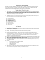
ACCESSORIES AND EQUIPMENT WITH THIS GENERATOR SET INCLUDES:
ITEM
PAGE
SAFETY RECOMMENDATIONS: These recommendations must be read and followed
to safely operate your generator set.
1
VOLTAGE RATINGS: This informational page describes features and specifications for
all Towable Units.
7
ELECTRICAL CONNECTION INFORMATION: This information explains how to interface
your generator with the AC loads and other standard and optional accessories.
9
CONTROL PANEL: This includes a drawing of the control panel and a description of
the components associated with it.
11
PRE–START PROCEDURE: This described a pre–start check that should be performed
prior to initial start–up.
14
OPERATION GUIDE: Information on how to start, stop, and operate the generator set
is included here. Included also is information in regards to the operation of the
genset/ engine control device and the different fault shutdown circuits designed to
protect the generator set from potential engine operational problems.
15
TROUBLESHOOTING GUIDE: Included in this guide are basic instructions to help
troubleshoot most problems with your generator set. For more troubleshooting
help please contact the service department at Baldor Generators
18
HIGHWAY TRAILER: This includes information in regards to safe operation, proper
utilization, and recommended guidelines for using and operating the trailer.
23
BALDOR GENERATORS WARRANTIES: this details the warranty provided by Baldor
Generators for coverage for electrical generator end of the generator set.
27
OTHER MANUALS AND ACCESSORIES THAT SHOULD ACCOMPANY YOUR TOWABLE
GENERATOR:
ENGINE OPERATOR’S MANUAL: This operator’s manual includes information in regards to
the operation and maintenance of the engine utilized in this generator set.
AC GENERATOR, ACCESSORIES, AND LOAD CONNECTION DIAGRAMS / ENGINE
CONTROLS, ACCESSORIES, AND REMOTE CONNECTION DIAGRAMS: These diagrams contain information in regards to the internal wiring of the generator set, specifically the AC and
Engine Control circuits. These diagrams will also include information for any optional AC
or DC powered accessories that are included.
PARTS LIST: This is a listing of all parts used by Baldor Generators to build this specific generator set.
SAFETY WARNINGS
z Place protective covers and guards over the rotating parts, if rotating parts such as the drive shaft, pulley,
belt, etc. are left exposed, they are potentially hazardous.
z When cleaning, repairing or inspecting, make sure all moving parts have stopped.
z Prior to working on the generator set, disconnect the spark plug and battery to prevent accidental starting.
z Use only original equipment or authorized replacement parts. Use of correct parts will assure the operator
of the safety integrity that was designed into the unit.
z Unauthorized modifications to the generator set may impair the function and/or safety of the unit.
z Do not operate the generator set without a muffler. Inspect periodically and replace if necessary.
z Do not touch the hot exhaust components or the high voltage spark plug and coil terminals. While Spark
Plug Voltages are not normally lethal, an involuntary jerk of the hand caused by a hot surface or by
an electrical shock can result in injury.
z Repair of electrical generating equipment requires specialized skills. Repair personnel must have a
thorough understanding of generator and small engine repair procedures.
z Never inhale exhaust gases. They contain carbon monoxide; a colorless, odorless and extremely
dangerous gas that can cause unconsciousness or death. Symptoms of carbon monoxide poisoning
can include: dizziness, nausea, headaches, sleepiness, vomiting or incoherency. If you or anyone else
experiences any of these symptoms, get out into the fresh air immediately. Shut the unit down and
do not operate it until it has been inspected and, if necessary, repaired.
z Never Operate the generator set indoors or in a poorly ventilated area such as a tunnel or cave.
z CALIFORNIA PROPOSITION 65 WARNING: engine exhaust from this product contains chemicals known
to the state of California to cause cancer, birth defects or other reproductive harm.
z Know how to stop the engine quickly and understand the operation of all controls.
Revised: 8/13/02
Effective: 2/27/98
Page 1 of 4
1
FORM#: S–PSG–001–3
C:\ISO9001\FORMS\SPSG0013.msw.bbk
SAFETY WARNINGS
z Never permit anyone to operate the generator set without proper instructions.
z Never allow children to operate the generator set.
z Children and pets must be kept away from the area of operation due to the possibility of burns from hot
engine components or injury from any equipment the generator set is powering.
z Always wear eye protection and Hearing protection when working near the generator set.
z Operate the generator set only with the guards, shields and other safety items in place and working
properly.
z Do not put hands, feet, tools or other objects near rotating parts.
z Use reasonable care when moving or lifting the unit. The generator set may move around inside the wrap
frame creating ”Pinch Points”.
z Do not run the generator set while it is being moved.
z Do not support the generator set from the top of the wrap frame.
z Do not operate the generator set while under the influence of alcohol, drugs or medication.
z When transporting or using a generator set with the wheel option, secure the unit to prevent it from moving
around.
z Do not tamper with or change the engine speed as it has been preset at the factory for proper operation.
z Keep hands and face away from the carburetor when the air cleaner is being moved. A sudden backfire
can cause serious burns.
z Be careful of hot parts. The muffler and other generator parts become very hot while the engine is running.
z Do not ”jump start” the generator set.
z Sulfuric acid can cause severe injury and can give off gases, which are corrosive and potentially explosive.
Avoid contact with skin, eyes, and clothing. In case of contact, flush area immediately with water.
z When transporting a generator set, secure it to prevent it from moving or shifting.
z Know how to stop the engine quickly and understand the operation of all controls.
z Do not operate electrical equipment while standing in water, on wet ground or with wet hands or shoes.
z Use extreme caution when working on electrical components. Potentially dangerous voltage is present
when the engine is running.
Revised: 8/13/02
Effective: 2/27/98
Page 2 of 4
2
FORM#: S–PSG–001–3
C:\ISO9001\FORMS\SPSG0013.msw.bbk
SAFETY WARNINGS
z Always treat the electrical circuits as if they were energized.
z Disconnect all leads plugged into the unit Prior to working on it.
z Have the electrical circuits serviced only by qualified technicians.
z Inspect wiring frequently and replace frayed, broken or poor leads.
z Do not connect this unit to any building’s electrical system unless you utilize an approved transfer switch or
the main service entrance switch has been disconnected and locked open.
z Circuit overload protection must be provided in accordance with national electrical codes and local
regulations.
z Check GFCI Receptacles monthly by using the ”Test” and ”Reset” buttons designed into them.
z Depending on your application it may be mandatory to ground or not ground this unit to earth ground.
Comply with local electrical codes.
````
FOR GASOLINE OR DIESEL POWERED GENERATOR SETS ````
z Operate the generator set on a level surface. If the generator set is tilted, fuel spillage may result.
z Handle fuel with care. It is highly flammable. Use only clean, properly marked and approved safety
containers for refueling and storing fuel.
z Stop the engine and allow it to cool before refueling.
z Do not overfill the fuel tank. Only fill the tank to within 1/2” of the top of the tank to allow space for fuel
expansion.
z If fuel is spilled, wipe it up carefully and wait until the fuel has dried before starting the engine.
z Make sure the fuel cap is properly closed after refueling.
z Never operate the generator set while smoking.
z Never operate the generator set near an open flame.
z Never store the generator set with fuel in the tank indoors or in an enclosed, poorly ventilated enclosure
where fuel fumes may reach an open flame, electrical spark or pilot light as on a furnace, water heater,
clothes dryer, etc.
z When transporting over long distances or rough roads, drain the fuel tank to prevent leakage and spillage.
Revised: 8/13/02
Effective: 2/27/98
Page 3 of 4
3
FORM#: S–PSG–001–3
C:\ISO9001\FORMS\SPSG0013.msw.bbk
SAFETY WARNINGS
```` FOR GASOLINE OR DIESEL POWERED GENERATOR SETS ````
z Check all fuel supply piping and their connections on a monthly basis for fuel leaks.
z Use only approved piping and componentry in your fuel supply system.
z A professional, experienced technician should only install the fuel supply system.
z Do not run the fuel line up against any sharp objects.
z Comply with NFPA regulations and your local codes in regard to shut–off valves, regulators, etc. and any
other recommendations or requirements they may have.
z Keep the generator set at least three feet away from buildings or other structures.
z Keep the generator set away from flammable and other hazardous materials (trash, rags, lubricants,
explosives, paints, etc.)
z Keep the generator set free of grass, leaves and excessive grease and oils.
z Allow the generator set to cool before transporting it or storing it indoors.
z Have fire extinguisher accessible and nearby while operating the generator set.
z This generator set must not be used on or near any forest covered brush covered or grass covered land
unless the engine’s exhaust system is equipped with a spark arrester and it must be maintained
in effective working order by the operator.
z Operation inside an enclosed compartment or building is a potential fire hazard and should not be done
unless approval is obtained from Baldor Generators. Engine/Generator overheating can cause severe
damage due to restricted, obstructed or improper air–flow that is necessary for the proper cooling of the
unit.
z Hot exhaust gases being discharged by the engine must never be directed toward anything that could
catch fire or explode.
Revised: 8/13/02
Effective: 2/27/98
Page 4 of 4
4
FORM#: S–PSG–001–3
C:\ISO9001\FORMS\SPSG0013.msw.bbk
FORWARD
This manual contains the information you need to safely and efficiently operate your generator
set. During the preparation of this manual every effort was made to ensure the accuracy of its
contents.
Never operate this generator set without first carefully reading this manual and observing all the
safety warnings it presents. While safety is built into every Baldor Pow’R Gard generator set,
careless or improper operation could possibly result in mechanical failure, property damage, severe injury or death.
Note that this manual covers only very basic information in regards to the engine. A separate
owner’s manual for the engine is supplied with this unit for your use. Please refer to this manual
for information relative to engine operation, maintenance, recommendations and additional
safety warnings.
As soon as you receive your generator set, inspect it closely for shipping damage. If you find
some damage, notify the transportation company immediately and file a freight damage claim.
Think of this manual as a tool to help you get the most out of your generator set. We strongly
suggest that you keep this manual with your generator set and refer to it when questions arise
in regards to its operation.
Baldor Generators, formerly Pow’R Gard Generator Corporation has been in business since
1965. The generator sets we manufacture have earned the reputation of being of high quality
and a dependable product. We take pride in this fact and continue to keep our quality standards
high on our list of priorities. We are also constantly researching new technological ideas to determine if they could be used to make our generator sets even better.
Thank you for purchasing your Baldor Pow’R Gard Generator Set.
Effective: February 26, 1998
Revised 2/01/02
Form#: S–CSD–003–7
C:\ISO9001\FORMS\SCSD0037.MSW
5
Effective: February 26, 1998
Revised 2/01/02
Form#: S–CSD–003–7
C:\ISO9001\FORMS\SCSD0037.MSW
6
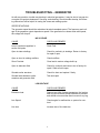
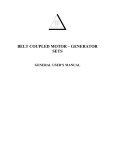
Features & Specifications
Model
Standby output–
(KVA/KW):
G
E
N
E
R
A
T
O
R
TS25
TS45
TS80
TS130
TS175
1500C Rise
3 PH @ 480 Volt
25/20
48/38
81/65
134/107
175/140
3 PH @ 208/240 Volt
25/20
46/37
72/58
131/105
169/135
1 PH @ 240 Volt
Continuous Output–
1250C Rise (KVA/KW):
18/18
27/27
45/45
70/70
80/80
3 PH @ 480 Volt
23/18
44/35
75/60
121/97
169/135
3 PH @ 208/240 Volt
23/18
44/35
69/55
119/95
156/125
1 PH @ 240 Volt
18/18
25/25
43/43
66/66
75/75
Voltage – 3 PH Adjustable
208/220/240/
416/440/460/480
208/220/240/
416/440/460/480
208/220/240/
416/440/460/480
208/220/240/
416/440/460/480
208/220/240/
416/440/460/480
Voltage – 1 PH Adjustable
120/127/139/
240/254/277
120/127/139/
240/254/277
120/127/139/
240/254/277
120/127/139/
240/254/277
120/127/139/
240/254/277
Amperage (Continuous):
3 PH 480 Volt
27.1
52.6
90.2
145.8
203.0
3 PH 208 Volt
62.5
121.4
190.8
329.6
433.7
3 PH 240 Volt
54.1
105.3
165.4
285.7
375.9
1 PH 240 Volt/120 Volt
75.0/150.0
104.2/208.3
179.2/358.3
275/550
312.5/625.0
120 Volt, 15 Amp GFCI
4
6
6
6
6
120/240 Volt, 50 Amp,
CS6369 Twistlock
Voltage Regulation 1/2%
2
3
3
3
3
1/2%
1/2%
1/2%
1/2%
1/2%
Power Factor – 3 Phase
0.8
0.8
0.8
.08
.08
Frequency
50 or 60 Hertz
50 or 60 Hertz
50 or 60 Hertz
50 or 60 Hertz
50 or 60 Hertz
Receptacles:
E
N
G
I
N
E
Total Harmonic Distortion
<5%
<5%
<5%
<5%
<5%
Insulation
Class F
Class F
Class F
Class F
Class F
Engine Make/Model
Isuzu
4LE
Isuzu
4BG1
John Deere
TO4045T
John Deere
TO6068
John Deere
RG6081T
Design
Water Cooled
4 Cycle Diesel
Water Cooled
4 Cycle Diesel
Water Cooled
4 Cycle Diesel
Water Cooled
4 Cycle Diesel
Water Cooled
4 Cycle Diesel
Starting System
12 VDC
12 VDC
12 VDC
12 VDC
12 VDC
Displacement (cid)
133.0
264.2
276.0
414.0
498.0
Cylinders
4
4
4
6
6
HP @ Rated Speed
34.5
64.0
100.0
166.0
211.0
RPM
1800
1800
1800
1800
1800
High Temperature
Std.
Std.
Std.
Std.
Std.
Low Oil
Std.
Std.
Std.
Std.
Std.
Overspeed
Std.
Std.
Std.
Std.
Std.
Overcrank
Std.
Std.
Std.
Std.
Std.
Fuel Capacity
50
80
80
160
160
1/2 Load
1.3
2.0
2.7
4.2
5.6
Full Load
2.0
3.4
4.9
8.1
10.5
1/2 Load
38
40
30
38
29
Full Load
25
24
16
20
15
750
900
900
(2) 750
(2) 750
With Trailer
123” x 62” x 70”
139” x 60” x 81”
139” x 60” x 81”
163” x 66” x 94”
163” x 66” x 94”
Without Trailer
74” x 38” x 52”
84” x 38” x 61”
84” x 38” x 61”
108” x 42” x 74”
108” x 42” x 74”
2265
1790
3540
2829
3848
3053
5600
4610
6200
5205
Safety Shutdowns:
Fuel Consumption (GPH):
Approx. Run Time (Hrs.):
Battery Recommendation Min. Cold
Cranking Amps
(Battery not included)
Dimensions (L x W x H):
Weight (Lbs.):
Without Fuel
Without Fuel & Trailer
7
8
SWITCHABLE
ELECTRICAL CONNECTION INFORMATION
WARNING:
High voltage may be present at receptacles and load studs while engine is
operating – DANGER of electrical shock is present. Use extreme care.
LOAD RECEPTACLES
1.
2.
Voltage is present in 120/240 volt switch position only.
Load wires may be brought into receptacle compartment through access door at control station.
HARD WIRE LOAD TERMINAL BLOCK
1.
2.
3.
4.
5.
Voltage available at load block is outlined in chart below.
Cables must be brought into load block compartment through access hole in base of trailer.
Opening load block door will cause load disconnect to trip.
Do not start engine with load turned “on”. Allow engine to come up to speed and warm up (1).
If left unattended, lock all doors to prevent tampering or injury.
AVAILABLE VOLTAGE:
SWITCH POSITION
277/480
120/240
120/208
STUD
1–2–3 = 480 VAC, 3 Phase
1–N, 2–N, 3–N = 277 VAC, 1 Phase
1–2–3 = 240 VAC, 3 Phase
2–3 = 240 VAC, 1 Phase
2–N, 3–N = 120 VAC, 1 Phase
1–N = 180 – 200 VAC, Wild Leg
1–2–3 = 208 VAC, 3 Phase
2–3 = 208 VAC, 1 Phase
1–N, 2–N, 3–N = 120 VAC, 1 Phase
NOTE:
To prevent damage to loads and generator, select voltage switch position prior to starting
engine.
NOTE:
Upon switching voltage selector switch, adjust voltage and adjust rheostat (located on engine
control panel) for proper voltage.
Revised: October 3, 2002
Effective: April 23, 1999
Form#: S–PSG–001–15
D:\ISO9001\FORMS\MSW’98bbk
9
CONNECTION INFORMATION
Your new Baldor Generator has all interconnecting wiring terminated at a junction box. All wiring will be
clearly labeled as being load; remote start contacts and AC input terminals and are to be connected as
described below.
Load – These connections are rated and sized according to the KW of the generator. Proper lead
wire from these points to the automatic transfer switch (or load switching device) is mandatory.
See enclosed transfer switch information for corresponding generator input terminals.
Remote Start Contacts – This two–wire connection, once connected to an appropriate switch,
will start the generator and perform as described in the remote start/stop literature. These
contacts are connected to the “Engine Start Contacts” of the automatic transfer switch.
A Two Pole normally open, closed to operate switch may also be used to start the generator.
AC Input – These connections are for units with float type battery chargers or engine block
heater combinations. A Constant supply of 120 volts AC (or as specified) is needed at these
terminals to power these devices.
NOTE: Power is not required when the unit is in operation. Internal battery charging and radiant heat
during operation eliminate the need for these devices.
NOTE: It is recommended that units utilizing an automatic transfer switch with adjustable time delays
have the initial adjustments made prior to start–up.
Factory recommendations are; allow a 2 second delay on start–up, 15–second delay on emergency to
normal.
Revised: March 20,2001
Effective: April 23, 1999
Form#: S–PSG–001–19
D:\ISO9001\FORMS\MSW’98bbk
10
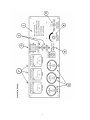
CONTROL PANEL OPERATION
AND FUNCTION
A. MASTER CONTROL SWITCH – This switch controls the starting and stopping of the engine via
the engine control logic circuitry.
With this switch in the “Manual” mode, the engine will start and run immediately after a
10 – 20 second time delay.
CAUTION: Please note that once the engine has been told to start, the gen set
should be treated as though it is operational, even though the start
delay has not yet allowed the engine to crank.
With this switch in the “Automatic” mode, the engine can be started and stopped from a remote
contact. (Standard switch, transfer switch, etc.) There is a time delay, to cool down, of 60–90
seconds when the unit is shut down from the remote contacts while the Master Control Switch is in
the “Automatic Mode.
With this switch in the “Off” position, the engine will immediately stop. The position must also be
utilized to clear fault shut–down conditions.
B. PANEL LIGHTS – By turning on the panel light switch, the panel lights will be energized and will
illuminate the control panel. The fuse next to the switch is to protect this circuit from damage due to
excessive current.
C. FIELD AND CONTROLLER FUSES – These fuses protect the internal workings of the generator
set.
D. GAUGES – These gauges monitor some of the more critical operating parameters of the engine as
well as the run time of the generator set.
The Voltmeter displays the charging rate that is currently being produced by the engine’s alternator to
facilitate the charging of the battery. This gauge should normally be above 12.5V whenever the unit is
running. If you ever notice the gauge is reading below 12V while the engine is running please contact
the service department at Baldor Generators.
The Temperature Gauge monitors and displays the operating temperature of the engines coolant. The
point at which a fault shut–down will occur is approximately 230°F.
The Oil Pressure Gauge displays and monitors the current operating pressure of the engine’s oil
system. The trip point at which a fault shutdown will occur is approximately 15 PSI or below.
Fuel level is checked by the owner or is usually a separately supplied fuel tank.
The Hour Meter accumulates and displays the total running time of the generator set.
11
E. VOLTAGE ADJUST – The rheostat allows the user to “fine tune” the generator set’s voltage
output. It is normally used to adjust output voltage after switching the output of the generator set to a
different voltage.
F. METERS – These meters monitor and display the current operating parameters of the generator set.
The Voltmeter monitors and displays the current operating AC output of the generator set.
The Hertz Meter monitors and displays the current operating frequency of the generator set.
The ammeter monitors and displays the amount of current that is being delivered by the generator set.
This meter works in conjunction with the Voltmeter Switch (Item G) in determining which output leg
to monitor.
G. AMMETER SWITCH – The switch allows the user to switch between L1, L2 and L3 to monitor the
current in each output leg of the generator.
H. PANEL LIGHT – By turning on the panel light switch, the panel lights (Not pictured on diagram)
will be energized and will illuminate the control panel.
I – SYSTEM FAULT INDICATORS – These lights will come on when a fault condition or a warning
condition develops.
The “Low Oil Pressure” light will come on when the engine’s oil pressure drops below 15 PSI. This
condition will trigger a fault shut–down and the unit will stop.
The “Over–crank” light will come on when the engine has failed to start after four attempted crank
cycles. Each crank cycle consists of a 12 second time period followed by a 12 second rest time
period.
The “Over–speed” light will come on when the engine’s operating speed rises above it’s normal
operating parameters. This condition will trigger a fault shut–down and the engine will stop.
High Temperature light will come on when the engine’s operating temperature exceeds the safety
set–point.
12
13
OPERATION – PRE–START PROCEDURE
1. Fill system fuel tank with clean, fresh diesel fuel.
CAUTION: Wipe up any and all fuel spillage.
2. Fill engine crankcase to full mark with clean, fresh lubricating oil per attached engine operating guide.
3. Radiator coolant should be checked at the beginning of each day and filled in compliance with the engine
manufacturer’s guidelines.
4. Secure the generator for operation.
Skid mounted – the power generating system should be mounted to a smooth,
hard surface suitable for supporting the system under all stress conditions.
Trailer mounted – block wheels to prevent accidental movement.
Adequate clearance must be provided for access doors to fully open.
NOTE: The generating system exhaust also exits radiator end. When
positioning a generator system ensure position does not cause a
concentration of toxic emissions.
14
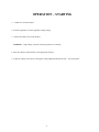
OPERATION – STARTING
1. Conduct ‘Pre–start Procedures.
2. Switch the generator set to the applicable voltage setting.
3. Connect the load(s) to the circuit breaker.
WARNING:
High voltage is present when the generator set is running.
4. Move the ‘Master Control Switch” to the appropriate position.
5. Adjust the voltage if necessary by turning the voltage adjustment knob located on
15
the control panel.
OPERATION
The prime mover utilized in this power generating system is controlled via an engine control module.
Starting is accomplished by commanding the control to ”start” the engine. This command can be
given by a number of controls.
? The operator control mounted on the front panel.
? The remote controls via the transfer switch or remote start terminal closure.
Initially, the system may be started and operated by placing the operator control in the ”manual/run”
position. To cease operation, return the switch to the ”off” position.
NOTE: Clear unit of all loose objects and perform all ”pre–start” procedures before operating
generator system.
ENGINE CONTROL MODULE:
The engine control module (ECM) is a microprocessor– based module that monitors the control and
safety inputs and provides all the required START and STOP functions automatically.
The following front panel controls and instruments are wired into the microprocessor through the
ECM terminal blocks:
1.
Run–Off–Auto Switch
a. * ”Run” – run position causes the generator set to start and run immediately.
b. * ”Auto” – auto position allows unit to be controlled via any remote single–pole ”dry” contact
(transfer switch, etc.). Contact closure causes the unit to start and run, while contact opening causes
unit to shut down after a preset cool down period.
c. ”Off” – unit operation is terminated.
* – units equipped with Isuzu engines may have a time delay glow plug cycle before starting.
2.
Lamp Test
Push button energizes all alarm lights simultaneously. This feature is disabled with the
run–stop–auto switch in the ”stop” position, and has no other effect on unit operation.
SAFETY INPUTS
1. Low Oil Pressure Shutdown – (LOP)
Monitoring of oil pressure begins for a preset time after unit starts and remains in effect until
unit is shut down (except as noted in ”loss of frequency input” below). The LOP signal is derived
from an oil pressure switch gauge mounted on the control panel
2.
High Temperature Shutdown – (HT)
The engine temperature monitoring begins immediately with the start signal. However, if engine
temperature is excessive prior to start (i.e., heat soak after shutdown), the unit is permitted to
start.
The high temperature condition is permitted to exist for up to 60 seconds after the unit is running
before shutdown when alarm occurs. If the excessive temperature condition is corrected within
that time period, the HT circuit reverts to normal monitoring. The HT signal is derived from a
monitoring device located on the prime mover.
16
3. Over–speed Adjustment – (OS) – Over Frequency
Over–speed protection is provided by a frequency sensing network within the controller. The trip
point of the frequency network is adjustable via a rheostat located on the top of the controller at
the right hand side. Clockwise (CW) rotation increases the trip frequency and, thereby, raises the
shutdown speed.
CRANKING CONTROL
1. Over–crank Protection
This feature provides a preset second crank cycle. Failure of the engine to start by the end of the
crank period results in an ”Over–crank” shutdown and alarm indication.
2. Cranking Disconnect Adjustment (CDS Adjustment)
The cranking disconnect signal is obtained by a frequency network within the controller. The trip
point of the frequency network is not adjustable.
LOSS OF FREQUENCY
Internal protection against loss of frequency input to the cranking disconnect circuit is programmed in
after the unit has started normally. In the event the frequency goes to zero (engine runs out of fuel,
frequency signal source fails, etc.) the LOP shutdown circuit is bypassed and a 12–second wait
period is initiated. If frequency returns within this time period, LOP monitoring resumes and operation
continues normally. If frequency has not returned at the end of this time period, the engine oil
pressure status is observed to determine whether the engine is actually running or stopped. If the
engine has stopped (i.e., air in fuel, etc.), the cranking cycle will begin in an effort to restart the
engine. If the engine has not stopped (loss of input signal, etc.), the unit is shutdown with an
”Over–crank” indication and alarm.
WARNING:
Over–crank indication can mean a loss of crank–disconnect signal during the
previous run period. Attempting to restart the engine with no crank–disconnect signal can
destroy the starter motor, which can cause serious personal injury.
This is of particular note since the tendency is to pursue only cranking and start related faults. The
cranking disconnect signal source is a key component in this system and must be checked out
thoroughly whenever an ”Over–crank” shutdown occurs.
NOTE:
The controller does not provide protection against loss of signal during start–up. A
shutdown with alarm, due to any of the above conditions, will prevent any subsequent
operation of the generator set. The run–stop–auto selector switch on the control panel
must be momentarily placed in the stop position to reset these functions.
CAUTION: If a dead battery is suspected, remove controller fuse, charge battery (or replace), and
then attempting starting. Damage to engine control may result from jump starting.
17
TROUBLESHOOTING – GENERATOR
As with any machine, trouble may develop in electrical generators. It may be due to long service
or neglect of regular maintenance. Servicing, and checking. Should trouble develop, the following instructions will be helpful in tracing the cause and making repairs.
SPEED DEVIATIONS:
The generator speed should be maintained at rated nameplate speed. The frequency and voltage of the generator output depends on speed. If the generator runs slower than rated speed,
the voltage will drop off.
NO VOLTAGE
CAUSE
CHECK AND REMEDY
Loss of residual magnetism in
exciter field poles.
Flash Field.
Open in stator windings
Check for continuity in windings. Return to factory
for repair if open
Open or short in rotating rectifiers.
Check rectifiers.
Short Circuited.
Clear lead to restore voltage build–up.
Open in alternator field
Check for continuity and return rotor to factory for
repair if field coils are open.
Shorted exciter armature
Check for short and replace if faulty.
Shorted leads between exciter
armature and generator field.
Test and repair
LOW VOLTAGE
CAUSE
CHECK AND REMEDY
Excessive load.
Reduce load. With 3 phase generators, the load on
each leg should be as evenly balanced as possible
and should not exceed the rated current on any leg.
Low Speed.
Check engine for malfunction or system for overload.
Line loss.
Increase size of line lead wire.
18
LOW VOLTAGE (Continued)
CAUSE
CHECK AND REMEDY
High resistance connections–
Connections will be warm or hot
Make better connection electrically and
mechanically.
Shorted field.
Test field coils for possible short by checking resistance with an ohmmeter or resistance bridge. Return rotor assembly to factory for repair if alternator
field coils are shorted.
Low power factor
Reduce inductive (motor) load. Some AC motors
Draw approximately the same current regardless of
load. Do not use motors of larger horsepower rating
than is necessary to carry the mechanical load.
FLUCTUATING VOLTAGE
(May be indicated by flickering lights.)
CAUSE
CHECK AND REMEDY
Irregular speed of engine.
Check engine for malfunction or load for fluctuation.
Fluctuating speed.
Stabilize load. The addition of a lamp load (resistance load) may compensate partially for load
changes caused by intermittent motor operation.
Do not overload.
Loose terminal or load connections.
Make better connection mechanically and electrically.
Defective bearing causing uneven air gap. Replace worn bearing.
HIGH VOLTAGE
CAUSE
CHECK AND REMEDY
Excessive speed.
Check engine for malfunction.
OVERHEATING
CAUSE
CHECK AND REMEDY
Generator overloaded.
Reduce load. (Check with ammeter and compare
with nameplate rating.)
Clogged ventilating screens.
Clean air passages.
19
OVERHEATING (continued)
CAUSE
CHECK AND REMEDY
High room temperature.
Improve ventilation.
Insufficient circulation.
Provide cross–ventilation.
Low power factory.
Reduce inductive loads or install power factor improvement capacitors.
Unbalanced load
The load on each leg should be as evenly balanced
as possible and should not exceed the rated current on any leg.
Dry bearing.
Replace bearing.
MECHANICAL NOISE
CAUSE
CHECK AND REMEDY
Defective bearing.
Replace bearing.
Rotor scrubbing on stator.
Bad bearing; replace. Bent shaft, return to factory.
Loosen end bell, tighten; loose drive discs, tighten.
Loose laminations.
Return to factory.
Loose or misaligned coupling.
Tighten or align.
GENERATOR FRAME PRODUCES SHOCK WHEN TOUCHED
CAUSE
CHECK AND REMEDY
Static charge.
Ground generator frame.
Grounded armature or field coil.
Return to factory for repair.
20
TROUBLESHOOTING – ENGINE
CODE LIST OF POSSIBLE CAUSES
1. Battery capacity low.
2. Bad electrical connections.
3. Fault in starter motor.
4. Fault in starter motor.
5. Wrong grade of lubricating oil.
6. Low engine speed from starter motor.
7. Stop control fault.
8. Restriction in fuel lift pipe.
9. Fault in fuel lift pump.
10. Dirty fuel filter element.
11. Restriction in air filter or induction system.
12. Air in fuel system.
13. Fault in fuel injection pump.
14. Fault in atomizers or not correct type.
15. Cold start equipment not used correctly.
16. Fault in cold start equipment.
17. Broken fuel injection pump drive.
18. Fuel injection pump timing not correct.
19. Valve timing not correct.
20. Bad compression.
21. restriction in fuel tank vent.
22. Type or grade of fuel not correct.
23. Restriction of engine speed control movement.
24. Restriction in exhaust pipe.
25. Cylinder head gasket leaks.
26. Engine temperature too high.
27. Engine temperature too low.
28. Valve tip clearances not correct.
29. Valves not free.
30. Wrong high pressure pipes.
31. Worn cylinder bores.
32. Valves and seats do not seal correctly.
33. Piston rings not free or are worn or broken.
34. Valve stems and/or guide worn.
35.West type air cleaner too full or wrong oil used.
36. Crankshaft bearings worn or damaged..
37. Not enough lubricating oil in the pump.
38. Gauge not correct.
39. Lubricating oil pump worn.
40. Relief valve not free to close.
41. Relief valve not free to open.
42. Relief valve spring broken.
43. Fault in suction pipe of lubricating oil pump.
44. Dirty lubricating oil filter element.
45. Piston damaged.
46. Piston height not correct.
47. Fan damaged.
48. Fault in engine mounting (housing).
49. Flywheel housing or flywheel not aligned
correctly.
50. Fault in thermostat or wrong type.
51. Restriction in coolant passages.
52. Water pump drive belt loose.
53. Restriction in radiator.
54. Fault in water pump.
55. Restriction in breather pipe.
56. Damaged valve stem oil seals (where used).
57. Not enough coolant in system.
58. Restriction in sump strainer.
59. Valve spring broken.
60. Fault in exhaust or vacuum pipe leakage.
61. Turbo charger impeller damage, or dirty impeller.
62. Turbo charger lubricating oil seal leaks.
63. Induction system leaks (turbo charged engines.)
21
22
MAGNAPLUS GENERATOR
280 -- 430 Frame
Installation, Operation and Maintenance
Manual
Marathon Electric
A Subsidiary of Regal-Beloit Corp.
100 East Randolph Street
P.O. Box 8003
W ausau, W I 54402-8003
Phone: (715) 675 3311
Fax:
(715) 675 6361
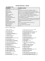
TABLE OF CONTENTS
SAFETY ..............................................................................................................................................................................................4
4
RECEIVING AND STORAGE .........................................................................................................................................................4
4
UNPACKING AND HANDLING ...................................................................................................................................................4
4
STORAGE........................................................................................................................................................................................4
4
PRINCIPLES OF OPERATION ......................................................................................................................................................5
5
5
FIGURE 1 -- MAGNAPLUS CIRCUIT DIAGRAM ...............................................................................................................................5
5
FIGURE 2 -- TYPICAL MAGNAPLUS LAYOUT DIAGRAM.................................................................................................................5
6
VOLTAGE REGULATION .....................................................................................................................................................................6
MOTOR STARTING .......................................................................................................................................................................6
6
PARALLEL OPERATION ..............................................................................................................................................................6
6
NONLINEAR LOADING ................................................................................................................................................................6
6
INSTALLATION................................................................................................................................................................................6
6
PREPARATION FOR USE .............................................................................................................................................................6
6
GENERATOR MOUNTING ...........................................................................................................................................................7
7
Single Bearing Units. ...................................................................................................................................................................7
7
Two Bearing Generators -- Direct Drive .....................................................................................................................................7
7
Two Bearing Units -- Belt Driven.................................................................................................................................................7
7
END PLAY TESTING .....................................................................................................................................................................7
7
TORSIONAL VIBRATION.............................................................................................................................................................7
7
ENVIRONMENTAL CONSIDERATIONS .....................................................................................................................................8
8
WIRING CONNECTIONS................................................................................................................................................................8
8
OPERATION ....................................................................................................................................................................................1
11
PRE-START INSPECTION ..........................................................................................................................................................1
11
START-UP .....................................................................................................................................................................................1
11
SHUTDOWN PROCEDURE.........................................................................................................................................................1
12
MAINTENANCE .............................................................................................................................................................................1
12
DRYING WINDINGS ...................................................................................................................................................................1
13
Space Heaters .............................................................................................................................................................................1
13
Forced Air ..................................................................................................................................................................................1
13
TESTING ..........................................................................................................................................................................................1
13
13
VISUAL INSPECTION ........................................................................................................................................................................1
13
CONSTANT EXCITATION TEST .........................................................................................................................................................1
13
CONTINUITY / RESISTANCE TEST.....................................................................................................................................................1
14
INSULATION TEST ............................................................................................................................................................................1
DIODE TESTING ..........................................................................................................................................................................1
14
SERVICE ..........................................................................................................................................................................................1
14
GENERAL .....................................................................................................................................................................................1
14
FIELD FLASHING ........................................................................................................................................................................1
14
15
BEARING REMOVAL ........................................................................................................................................................................1
Opposite Drive End Bearing Bracket Removal. .........................................................................................................................1
15
Drive End Bearing Bracket Removal, ........................................................................................................................................1
15
Two Bearing Units......................................................................................................................................................................1
15
BEARING REPLACEMENT ........................................................................................................................................................1
15
15
RECTIFIER ASSEMBLY REMOVAL ....................................................................................................................................................1
15
DIODE REPLACEMENT .....................................................................................................................................................................1
2
RETURNED GOODS ......................................................................................................................................................................1
16
TROUBLESHOOTING ...................................................................................................................................................................1
16
GENERATOR PRODUCES NO VOLTAGE ................................................................................................................................1
17
GENERATOR PRODUCES LOW VOLTAGE, NO LOAD .........................................................................................................1
17
GENERATOR PRODUCES LOW VOLTAGE WHEN LOAD APPLIED ..................................................................................1
18
GENERATOR PRODUCES FLUCTUATING VOLTAGE ..........................................................................................................1
18
GENERATOR PRODUCES HIGH VOLTAGE............................................................................................................................1
18
GENERATOR BUILDS VOLTAGE FROM STARTUP, THEN GOES TO LOW (RESIDUAL) VOLTAGE ...........................1
19
GENERATOR IS OVERHEATING ..............................................................................................................................................1
19
GENERATOR PRODUCES MECHANICAL NOISE ..................................................................................................................1
19
EQUIPMENT RUNS NORMALLY ON UTILITY POWER, BUT WILL NOT RUN ON GENERATOR.................................1
19
SPECIFICATIONS ..........................................................................................................................................................................2
20
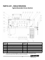
PARTS LIST – SINGLE BEARING...............................................................................................................................................2
21
Typical Generator Cross Section ...............................................................................................................................................2
21
PARTS LIST – DUAL BEARING ..................................................................................................................................................2
22
Typical Generator Cross Section ...............................................................................................................................................2
22
3
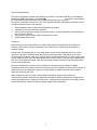
W hen in doubt, ask. Questions are much easier to handle
t h a n m i s t a k e s c a u s e d b y a m i s u n d e rs t a n d i n g o f t h e
i n f o rm a t i o n p re s e n t e d i n t h i s m a n u a l .
SAFETY
PLEASE REMEMBER SAFETY FIRST. If you are not sure
o f t h e i n s t ru c t i o n s o r p ro c e d u re s c o n t a i n e d h e re i n , s e e k
q u a l i f i e d h e l p b e f o re c o n t i n u i n g .
RECEIVING AND STORAGE
RECEIVING AND STORAGE
This service manual emphasizes the safety precautions
n e c e s s a ry d u ri n g t h e i n s t a l l a t i o n , o p e ra t i o n , a n d
maintenance of your MagnaPLUS generator. Each section
of this manual has caution and warning messages. These
messages are for your safety, and the safety of the
equipment involved. If any of these cautions or warnings is
n o t re a d i l y u n d e rs t o o d , s e e k c l a ri f i c a t i o n f ro m q u a l i f i e d
p e rs o n n e l b e f o re p ro c e e d i n g .
Upon receipt of the generator, it is recommended that it be
carefully examined for possible shipping damage. The
generator was given to the freight carrier in good condition;
t h u s , t h e c a rri e r i s re s p o n s i b l e f o r t h e p ro d u c t f ro m t h e
factory dock to the destination. Any damage should be
noted on the freight bill before accepting the shipment. Any
claims for damage must be promptly filed with the delivering
c a rri e r.
Before any service work is done, disconnect all power
sources and lock out all controls to prevent an unexpected
start-up of the generator set driver. Proper grounding
(earthing) of the generator frame and distribution system in
compliance with local and national electrical codes and
specific site requirements must be provided. These safety
precautions are necessary to prevent potential serious
personal injury, or even death.
UNPACKING AND HANDLING
Carefully read all instruction tags shipped with the unit.
W hen lifting, attach an overhead crane to the lifting lug(s) on
the generator frame. Apply lifting forces in a vertical
d i re c t i o n . W h e n t ra n s p o rt i n g s i n g l e b e a ri n g g e n e ra t o rs , t h e
generator’s rotor must be adequately supported to prevent
dam age.
The hazards associated with lifting or moving your
MagnaPLUS generator are pointed out in the installation and
maintenance sections. Incorrect lifting or moving can result
i n p e rs o n a l i n j u ry o r d a m a g e t o t h e u n i t .
Prior to start-up of the unit ensure that all generator leads
a re p ro p e rl y c o n n e c t e d t o t h e g e n e ra t o r l i n k b o a rd l o c a t e d
inside the connection box. Always assume that there will be
voltage present at the generator terminals whenever the
generator's shaft is rotating, and proceed accordingly.
Residual voltage is present at the generator terminals and at
the automatic voltage regulator panel connections even with
the regulator fuse removed. Caution must be exercised, or
s e ri o u s i n j u ry o r d e a t h c a n re s u l t .
WARNING
THE LIFTING LUG (S) ON THE GENERATOR ARE
DESIGNED TO SUPPORT THE GENERATOR ONLY.
DO NOT LIFT A COMPLETE GENERATOR AND
DRIVER ASSEMBLY BY MEANS OF LIFTING LUG (S)
ON THE GENERATOR. PERSONAL INJURY OR
EQUIPMENT DAMAGE MAY RESULT.
This manual is not intended to be a substitute for properly
t ra i n e d p e rs o n n e l . I n s t a l l a t i o n a n d re p a i rs s h o u l d o n l y b e
attempted by qualified, trained people. The cautions and
warnings point out known conditions and situations that are
potentially hazardous. Each installation may well create its
own set of hazards
STORAGE
In the event that the generator is not immediately installed
on its prime mover, it is recommended that the unit be stored
indoors in a clean, dry area, which is not subject to rapid
changes in temperature and humidity. If the generator is
s t o re d f o r a l o n g p e ri o d o f t i m e , t h e g e n e ra t o r s h o u l d b e
t e s t e d , c l e a n e d a n d d ri e d a s re q u i re d b e f o re b e i n g p u t i n t o
service. See the maintenance section of this manual for
f u rt h e r i n f o rm a t i o n . I f t h e u n i t h a s b e e n s t o re d i n a n a re a
where it has been subject to vibration, it is recommended
that the bearing(s) be inspected and replaced as necessary.
4
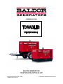
PRINCIPLES OF OPERATION
PMG (optional)
PMG Field
(rotor)
Rotating Assembly
Exciter Field
(stator)
Main Field
(rotor)
Exciter Armature
(rotor)
Main Armature
(stator)
L1
N
S
(+)
(+)
DC
(in)
DC
(in)
(-)
L2
(-)
3 Phase AC (out)
3 Phase AC (out)
PMG
Armature
(stator)
Rotating Rectifier Assembly
3 Phase -- Full Bridge
Exciter Field Power
(DC out)
PMG Input Power (optional)
(1 phase, 300/250 hertz)
Input Power -- Single Phase
(shunt powered regulator)
Automatic
Voltage
Regulator
Sensing Input -- Single Phase
3 phase (optional)
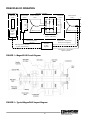
FIGURE 1 -- MagnaPLUS Circuit Diagram
FIGURE 2 -- Typical MagnaPLUS Layout Diagram
5
L3
generators generally supply .3 to .4 horsepower per
generator kW in motor starting capability. For specific data
contact Marathon Electric.
PRINCIPLE OF OPERATION
MagnaPLUS generators are a brushless, self excited, and
externally voltage regulated, synchronous AC generator.
The generator is made up of six major components: main
stator (armature), main rotor (field), exciter stator (field),
exciter rotor (armature), rectifier assembly, and voltage
regulator. In understanding the above terminology, note the
following: stators are stationary, rotors rotate, a field is an
e l e c t ri c a l i n p u t , a n d a n a rm a t u re i s a n e l e c t ri c a l o u t p u t .
These system components are electrically interconnected as
shown in figure 1 and physically located as shown in
f i g u re 2 .
PARALLEL OPERATION
All MagnaPlus generators are built with 2/3 pitch main stator
windings and full amortisseur (damper) windings. These
features make the MagnaPlus generators suitable for parallel
operation when equipped with the proper voltage regulators
and voltage regulator accessories. Consult with the factory
for further information relative to parallel operations.
The generator’s exciter consists of a stationary field and a
rotating armature. The stationary field (exciter stator) is
d e s i g n e d t o b e t h e p ri m a ry s o u rc e o f t h e g e n e ra t o r’ s re s i d u a l
magnetism. This residual magnetism allows the exciter rotor
(armature) to produce AC voltage even when the exciter
stator (field) is not powered. This AC voltage is rectified to
DC by the rotating rectifier assembly and fed directly to the
main rotor (field). As the generator shaft continues to rotate,
the main rotor (field) induces a voltage into the generator's
main stator (armature). At rated speed, the main stator’s
voltage produced by the residual magnetism of the exciter
allows the automatic voltage regulator to function. The
regulator provides voltage to the exciter resulting in a buildup of generator terminal voltage. This system of using
re s i d u a l m a g n e t i s m e l i m i n a t e s t h e n e e d f o r a s p e c i a l f i e l d
flashing circuit in the regulator. After the generator has
established the initial residual voltage, the regulator provides
a controlled DC field voltage to the exciter stator resulting in
a controlled generator terminal voltage.
NONLINEAR LOADING
Solid state electronic control devices (variable frequency
drives, precision motor controls, battery chargers, etc.) utilize
electronic switching circuits (thyristors, SCRs, Diodes, etc.).
These switching circuits introduce high frequency harmonics,
which distort the normal waveform of the generator. This
creates additional heat in the generator windings and may
cause the generator to over-heat. Problems that can occur
are not limited to the generator. Poor wave shape may
adversely effect various loads connected to the generator.
Consult Marathon Electric for further information relative to
nonlinear loads .
INSTALLATION
Voltage Regulation
PREPARATION FOR USE
In the standard configuration (shunt excited), the automatic
voltage regulator receives both its input power and voltage
sensing from the generator's output terminals (See Figure 1).
W ith the optional PMG configuration, the regulator receives
input power from the PMG. The regulator automatically
monitors the generator's output voltage against an internal
reference set point and provides the necessary DC output
voltage to the exciter field required to maintain constant
generator terminal voltage.
Adjusting the regulator's
reference set point changes the generator's terminal voltage.
Consult the regulator manual for specific adjustment and
o p e ra t i n g i n s t ru c t i o n s .
Although the generator has been carefully inspected and
tested in operation prior to shipment from the factory, it is
re c o m m e n d e d t h a t t h e g e n e ra t o r b e t h o ro u g h l y i n s p e c t e d .
Check all bolts for tightness and examine the insulation on
lead wires for chafing prior to proceeding with installation.
Remove all shipping tapes, bags, skids and rotor support
blocking. For two bearing units, rotate the shaft by hand to
ensure that it rotates smoothly without binding.
MOTOR STARTING
W hen a motor is started, the motor draws a large surge of
current. This starting current is equivalent to the motors
l o c k e d ro t o r o r s t a l l c u rre n t a n d i s 5 t o 1 0 t i m e s ' n o rm a l f u l l
l o a d c u rre n t . W h e n t h e g e n e ra t o r s u p p l i e s t h i s i n -ru s h o f
starting current, the generator voltage dips temporarily. If
t h e m o t o r i s t o o l a rg e f o r t h e g e n e ra t o r, t h e g e n e ra t o r’ s
voltage dips greater than 30 percent. This may result in the
motor starter de-energizing or the motor stalling. MagnaPlus
6
driver and the generator's shaft. Aligning the generator and
its driver as accurately as possible will reduce vibration,
increases bearing life, and ensure minimum coupling wear.
I t m a y b e n e c e s s a ry t o s h i m t h e g e n e ra t o r f e e t f o r p ro p e r
support and alignment. Secure the feet of the generator with
grade 5 or greater bolts through the holes provided in the
m o u n ti n g fe e t.
Consult the coupling manufacturer's
i n s t ru c t i o n s f o r a l i g n m e n t s p e c i f i c a t i o n s a n d p ro c e d u re s .
WARNING
DISABLE AND LOCKOUT ANY ENGINE CRANKING
DEVICES BEFORE ATTEMPTING TO INSTALL OR
SERVICE THE GENERATOR.
FOR ELECTRIC
START SETS, DISCONNECT THE CRANKING
BATTERY. FOR AIR START, DISCONNECT THE AIR
SUPPLY. FOR MOTOR GENERATOR SETS, OPEN
THE POWER SUPPLY TO THE DRIVE MOTOR.
FAILURE TO COMPLY WITH THESE SAFETY
PROCEDURES COULD RESULT IN SEVERE
PERSONAL INJURY OR EQUIPMENT DAMAGE.
GENERATOR MOUNTING
Two Bearing Units -- Belt Driven
Two bearing MagnaPLUS generators can be belt driven
provided belts are sized and applied correctly. Please refer
to your supplier of belts and sheaves for correct sizing and
t e n s i o n i n g s p e c i f i c a t i o n s . A b e a ri n g l i f e c a l c u l a t i o n s h o u l d
be performed. Marathon Electric recommends a minimum
B-10 life of 40,000 hours. If cog type belts are used, a
vibration may be introduced which could lead to premature
f a i l u re o f t h e b e a ri n g s .
NEVER "BAR OVER" THE ENGINE GENERATOR
SET USING THE GENERATOR'S FAN. THE FAN IS
NOT DESIGNED FOR THIS PURPOSE. BARRING
OVER THE SET WITH THE FAN COULD DAMAGE
THE FAN AND RESULT IN PERSONAL INJURY OR
EQUIPMENT DAMAGE.
GENERATOR MOUNTING
END PLAY TESTING
Single Bearing Units.
Refer to the engine manual for recommended endplay
s p e c i f i c a t i o n s a n d m e a s u re m e n t p ro c e d u re s . I f e n d p l a y i s
n o t t o s p e c i f i c a t i o n , i t i s a n i n d i c a t i o n t h a t t h e g e n e ra t o r s h a f t
is not moving freely in the assembly, and normal life of the
thrust bearing could be impaired. Probable causes of this
p ro b l e m a re :
Single bearing units are provided with an SAE flywheel
housing adapter flange and flexible drive discs. Coupling the
generator's shaft to the engine flywheel is accomplished with
special steel drive discs bolted to the shaft. In addition to the
drive discs, there may be a hub spacer, spacer discs, or a
c o m b i n a t i o n o f h u b s p a c e r a n d s p a c e r d i s c s i n s e rt e d
between the drive discs and the shaft to achieve the proper
shaft extension ("G" dimension per SAE J620c). Holes are
provided in the periphery of the coupling discs, which
correspond to tapped holes in the prime mover's flywheel.
The outside diameter of the drive discs fit in a rabbet in the
flywheel so that concentricity is assured.
1. Improper seating of drive discs in the flywheel resulting in
m i s a l i g n m e n t.
2. Improper mating of generator frame to engine flywheel
h o u s i n g re s u l t i n g i n m i s a l i g n m e n t .
3. Improper "G" dimension per SAE J620c on either the
e n g i n e o r g e n e ra t o r.
Grade 8 place bolts and hardened washers are
recommended to mount the drive discs to the flywheel. DO
NOT USE SPLIT TYPE LOCK W ASHERS. Split lock
washers when biting into the drive disc cause stress risers,
which may result in the disc fracturing.
TORSIONAL VIBRATION
The SAE flywheel housing adapter ring and the engine
flywheel housing are designed to match each other with no
further alignment necessary.
Use grade 5 or greater
m o u n ti n g b o l ts .
MagnaPLUS generator frames are
constructed with two or three boltholes per foot. The feet
should be shimmed where necessary to obtain solid contact
with the sub-base. W ith the frame securely bolted to the
engine flywheel housing, there is no side thrust or pull on the
generator frame, thus no real need to secure the feet with
m o re t h a n o n e b o l t p e r f o o t .
Torsional vibrations are generated in all rotating shaft
systems. In some cases, the amplitude of these vibrations
a t c ri t i c a l s p e e d s m a y c a u s e d a m a g e t o t h e g e n e ra t o r, i t s
driver, or both. It is therefore necessary to examine the
torsional vibration effect on the entire rotating system. IT IS
THE RESPONSIBILITY OF THE GENERATOR SET
ASSEMBLER
TO
ASSURE
THE
TORSIONAL
COMPATIBILITY OF THE GENERATOR AND ITS DRIVER.
Drawings showing pertinent dimensions and weights of the
rotating assembly will be supplied by Marathon Electric upon
re q u e s t .
GENERATOR MOUNTING
Two Bearing Generators -- Direct Drive
Two bearing generators are provided with a keyed shaft
extension.
For direct drive generators, the assembler
furnishes a flexible coupling, which is installed between the
7
with the conduit. To minimize the transmission of vibration, it
is essential that flexible conduit be used for all electrical
entrance to the generator conduit box.
ENVIRONMENTAL
CONSIDERATIONS
All MagnaPLUS generators are equipped with link boards
(terminal strips) for both internal and external connections.
All connections made to the studs of the link board should be
made with high quality ring terminals. Ring terminal sizes
are 6 mm (280 Series Frames) and 10 mm (360 and 430
Series Frames). Torque link board connections to the
following specifications: 280 frame -- 5.4 NM (4 Ft LB); 360 &
430 frame -- 27 NM (20 Ft LB).
The MagnaPLUS generator is designed for heavy-duty
industrial applications; however, dirt, moisture, heat and
vibrations are enemies of rotating electrical machinery.
Excessive exposure to the elements may shorten generator
life. The temperature of the cooling air entering the intake
openings of the generator should not exceed the ambient
temperature shown on the generator’s nameplate.
Generators intended for outdoor application should be
protected with housings having adequate ventilation.
Although the standard insulation systems are moisture and
h u m i d i t y re s i s t a n t , s p a c e h e a t e rs a re re c o m m e n d e d f o r
extreme conditions. If the generator is to be installed in an
area where blowing sand and dust are present, the
enclosure should be fitted with filters. Filters reduce erosion
on the generator's insulation by blocking high velocity
abrasive particles generated by the flow of cooling air
through the generator. Consult the factory for appropriate
f i l t e rs a n d g e n e ra t o r d e ra t i n g s re q u i re d .
Refer to the connection diagram supplied with the generator
and / or the proper diagrams shown in this manual. Install all
inter-component and external wiring in accordance with
national and local electrical codes. The neutral in the
following connection diagrams shown below may be either
grounded (earthed) or left above ground potential (floating).
See national and local codes and / or the system distribution
wiring schematic diagram for the proper connection of the
n e u t ra l .
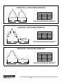
The following connection diagrams are shown for twelve
lead generators. Ten lead generators have the same
terminal designations except for leads T10, T11, and
T12. These three leads are internally connected inside
the generator and brought out as a single lead (T0). Ten
lead generators can only be connected in a wye
configuration
WIRING CONNECTIONS
Wiring of the generator and accessories should be
done in accordance with good electrical practices.
Follow government, industry and association
standards.
The generator conduit box construction allows cable entry
f ro m m u l t i p l e s i d e s . A h o l e s a w o r o t h e r a p p ro p ri a t e t o o l
may be used to provide for conduit entrance. Protect the
interior of the generator from shavings when drilling or
sawing. An approved connector must be used in conjunction
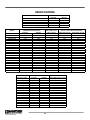
HIGH WYE CONNECTION
L1
T1
VOLTAGE (HIGH WYE)
Hz
L-L
L-N
60
480
277
460
266
440
254
416
240
380
219
50
416
240
400
231
380
219
T4
T7
T12
T6
T3
L3
T9
L-L
T10
T11
T8
T5
L-N
T2
L2
8
LOW WYE CONNECTION
L1
T7
T1
T10
T4
T12
VOLTAGE (LOW WYE)
Hz
L-L
L-N
60
240
139
230
133
220
127
208
120
190
110
50
208
120
200
115
190
110
L-L
T5
T9
T2
T6 T11
L3
T3
L2
T8
L-N
HIGH DELTA CONNECTION
T12
L1
T1
`
T6
L-L
T7
T3
L3
VOLTAGE (HIGH DELTA)
Hz
L-L
L-N
60
277
139
240
120
50
240
120
220
110
200
100
T4
T9
T10
T11
T8
T5
L2
T2
L-N
LOW DELTA CONNECTION
L1
T12
T1
T9
T3
L3
T4
T10
T11
VOLTAGE (LOW DELTA)
Hz
L-L
L-N
60
120
NA
110
NA
50
110
NA
100
NA
L-L
T6 T7
T8
T5
T2
L2
L-L
9
DOUBLE DELTA -- SINGLE PHASE CONNECTION
T3
T5
T6
L2
T11
T9
T2
T1
T8
T12
T4
VOLTAGE (DOUBLE DELTA)
Hz
L-L
L-N
60
240
120
220
110
50
220
110
T7
T10
L1
L-N
L-N
Note: Single-phase KW /KVA ratings are approximately
e q u a l t o 5 0 % o f t h e g e n e ra t o r’ s t h re e p h a s e ra t i n g s .
L-L
LOW ZIG ZAG -- SINGLE PHASE CONNECTION
T6
T2
VOLTAGE (LOW ZIGZAG)
Hz
L-L
L-N
60
240
120
220
110
50
220
110
200
100
T12 T8
T3
T9
T5
T11
L2
L-N
T4
T1
T10
T7
L1
Note: Single-phase KW /KVA ratings are approximately
e q u a l t o 5 0 % o f t h e g e n e ra t o r’ s t h re e p h a s e ra t i n g s .
L-N
L-L
HIGH ZIG ZAG -- SINGLE PHASE CONNECTION
T12
T1
T4
T9
T6
VOLTAGE (HIGH ZIGZAG)
Hz
L-L
L-N
60
480
240
460
220
50
415
208
380
190
T7
T3
T10
T11
T8
T5
L2
T2
L1
L-N
L-N
Note: Single-phase KW /KVA ratings are approximately
e q u a l t o 5 0 % o f t h e g e n e ra t o r’ s t h re e p h a s e ra t i n g s .
L-L
10
DEDICATED SINGLE PHASE CONNECTION
L1
T1
T2
T3
T4
VOLTAGE (DEDICATED)
Hz
L-L
L-N
60
240
120
220
110
50
220
110
200
100
L2
L-N
L-N
L-L
8.
Review all prime mover prestart-up instructions, and
e n s u re t h a t a l l re c o m m e n d e d s t e p s a n d p ro c e d u re s
have been followed.
9.
Remove any masking materials affixed during painting.
Inspect the generator, prime mover, and any accessory
e q u i p m e n t t o e n s u re t h a t n a m e p l a t e s , a n d a l l s a f e t y
warning / caution signs and decals provided with the
equipment are in place and clearly visible.
OPERATION
PRE-START INSPECTION
Before starting the generator for the first time, the following
i n s p e c t i o n c h e c k s a re re c o m m e n d e d :
1.
A visual inspection should be made for any loose parts,
b a d c o n n e c t i o n s , o r f o re i g n m a t e ri a l s .
2.
Bar the set over by hand for at least 2 revolutions to be
s u re t h a t t h e re i s n o i n t e rf e re n c e a n d t h a t t h e s e t t u rn s
freely. If the set does not turn freely, check for
clearance in the generator and exciter air gap.
3.
Check all wiring against the proper connection
d i a g ra m s , a n d e n s u re t h a t a l l c o n n e c t i o n s a n d
t e rm i n a t i o n s a re t i g h t a n d p ro p e rl y i n s u l a t e d .
Note: It is strongly recommended that the authority
having jurisdiction over the installation site be
consulted to determine if any additional warning or
caution notices, or additional safety devices are
required by local codes / standards. Any such
required notices or devices should be installed prior
to initial startup.
START-UP
WARNING
The following procedure should be followed when starting
t h e g e n e ra t o r s e t f o r t h e f i rs t t i m e .
MAGNAPLUS GENERATORS MAY HAVE VOLTAGE
PRESENT AT THE LEAD TERMINALS WHEN THE
SHAFT IS ROTATING.
DO NOT PERMIT
OPERATION OF THE GENERATOR UNTIL ALL
LEADS HAVE BEEN CONNECTED AND INSULATED.
FAILURE TO DO THIS MAY RESULT IN PERSONAL
INJURY OR EQUIPMENT DAMAGE
4.
Verify that all equipment is properly grounded (earthed).
5.
Clear the surrounding area of any materials that could
be drawn into the generator.
6.
Check all fasteners for tightness.
7.
Check all access plates, covers, screens and guards. If
they have been removed for assembly or inspection,
reinstall and check for security.
11
1.
The generator output must be disconnected from the
load. Be sure that the main circuit breaker or fused
d i s c o n n e c t i s i n th e o p e n p o s i ti o n .
2.
Open the input power to the automatic voltage regulator.
Remove the fuse or disconnect and insulate one of the
regulator input power leads. (See separate regulator
m anual)
3.
Verify that all prime mover start-up procedures have
been followed.
4.
If the unit is provided with space heaters, ensure that
they are de-energized. In some installations, a set of
auxiliary contacts on the main circuit breaker or transfer
switch will automatically open the space heater circuit
when the generator is connected to the load.
5.
Start the prime mover, and adjust it for proper speed.
See generator nameplate.
6.
The purpose of this initial test with the regulator out of
the circuit is to detect any wiring mistakes without
exposing the unit to undue risk. Check all line to line
and line to neutral voltages for balanced voltage. If
voltages are balanced shut down the set and reconnect
the regulator. If voltages are unbalanced, shut down the
equipment and check for improper wiring. If the problem
persists, consult the factory.
3.
MAINTENANCE
The following maintenance procedures should be followed to
e n s u re l o n g e q u i p m e n t l i f e a n d s a t i s f a c t o ry p e rf o rm a n c e .
Maintenance intervals will depend upon operating conditions.
W ith the regulator de-energized, the residual voltage
should be 10 - 25% of rated value. It is recommended
that this residual voltage and driver RPM be recorded for
u s e a s a f u t u re t ro u b l e s h o o t i n g b e n c h m a rk .
1.
Routinely check intake and exhaust air screens to
ensure that they are clean and free of debris. Clogged
intake air screens will reduce cooling airflow and result
in higher operating temperatures. This will reduce
g e n e ra t o r l i f e a n d m a y re s u l t i n g e n e ra t o r d a m a g e .
2.
All MagnaPLUS generators are equipped with double
s h i e l d e d b a l l b e a ri n g s l u b ri c a t e d f o r t h e l i f e o f t h e
bearing. Every 1,000 hours check the bearing(s) for
s m o o t h , q u i e t o p e ra t i o n .
Fo r c o n ti n u o u s d u ty
g e n e ra t o rs , re c o m m e n d e d p ra c t i c e i s t o re p l a c e t h e
bearing during major overhauls of the engine.
3.
Periodically inspect the unit for any buildup of
contamination (dirt, oil, etc.) on the windings. If the
wound components have become coated with heavy
c o n c e n t ra t i o n s o f o i l a n d g ri m e , t h e u n i t s h o u l d b e
disassembled and thoroughly cleaned. This operation is
not one that can be accomplished effectively on site, but
rather one that should be conducted by an authorized
service center equipped with the appropriate apparatus
and solvents necessary to properly clean and dry the
g e n e ra t o r.
WARNING
QUALIFIED ELECTRICAL PERSONNEL MUST
CONDUCT THE FOLLOWING TEST.
LETHAL
VOLTAGE MAY BE PRESENT AT BOTH THE
GENERATOR
AND
VOLTAGE
REGULATOR
TERMINALS DURING THIS PROCEDURE. CAUTION
MUST BE EXERCISED NOT TO COME INTO
PERSONAL CONTACT WITH LIVE TERMINALS,
LINKS, OR STUDS. SERIOUS INJURY OR DEATH
COULD RESULT.
7.
Start the set and adjust the terminal voltage to the
desired value by means of the regulator voltage
adjustment. If the regulator is equipped with a stability
a d j u s t m e n t , f o l l o w t h e i n s t ru c t i o n s i n t h e re g u l a t o r
manual to adjust the stability. Again, check all line to
line and line to neutral voltages for balance. It is
recommended practice to record the no load excitation
(DC voltage to the exciter stator), generator terminal
voltage, and driver speed as a benchmark for future
t ro u b l e s h o o t i n g .
8.
Close the main circuit breaker to the load.
9.
Monitor the generator output current to verify that it is at
or below nameplate value.
WARNING
QUALIFIED ELECTRICAL PERSONNEL MUST
CONDUCT THE FOLLOWING TEST.
LETHAL
VOLTAGE MAY BE PRESENT AT BOTH THE
GENERATOR
AND
VOLTAGE
REGULATOR
TERMINALS DURING THIS PROCEDURE. CAUTION
MUST BE EXERCISED NOT TO COME INTO
PERSONAL CONTACT WITH LIVE TERMINALS,
LINKS, OR STUDS. SERIOUS INJURY OR DEATH
COULD RESULT.
10. Check generator speed (frequency) under load. Adjust
as necessary. (Refer to prime mover or governor
m anuals )
SHUTDOWN PROCEDURE
4.
Every 2,000 operating hours or in conjunction with
scheduled engine maintenance check the DC no load
excitation voltage per item #7 in the startup procedure.
Compare this voltage with the value recorded during
initial startup. If this value of no load excitation voltage
i s m a rk e d l y h i g h e r t h a n t h e b e n c h m a rk re a d i n g , i t i s a n
indication of problems in the exciter, main field, or the
rotating rectifier assembly. Ensure that RPM is the
s a m e a s i n i ti a l te s t.
5.
Monitor and record insulation resistance with a 500 volt
mega-ohm meter. The minimum acceptable reading is
2 m e g a -o h m s . I f t h e re a d i n g d ro p s b e l o w t h e m i n i m u m ,
t h e g e n e ra t o r s h o u l d b e c l e a n e d a n d d ri e d a t a n
authorized service shop. Consult Marathon Electric for
m o re i n f o rm a t i o n .
There are no specific instructions for shutting down the
generator; however, several good practices should be
observed to prolong equipment life.
1.
2.
If the unit is equipped with space heaters, verify that the
heater circuit is energized.
It is advisable to disconnect all loads (open main circuit
breaker or disconnect) prior to shutdown. This is
e s p e c i a l l y i m p o rt a n t i f l o a d s c a n b e d a m a g e d b y l o w
voltage or low frequency conditions during generator
"coast down".
Isolate all conditions that could apply voltage to the
generator terminals while the generator is at rest.
F a i l u re t o c o m p l y c o u l d re s u l t i n p e rs o n n e l i n j u ry o r
equipm ent dam age.
12
DRYING WINDINGS
Generators in service may inadvertently have their windings
exposed to splashing or sprayed water. Units that have
b e e n i n t ra n s i t o r s t o ra g e f o r l o n g p e ri o d s o f t i m e m a y b e
subjected to extreme temperature and moisture changes
causing excessive condensation. Regardless of the source
of moisture, wet windings should be thoroughly dried out
b e f o re o p e ra t i n g t h e u n i t . I f t h i s p re c a u t i o n i s n o t t a k e n ,
serious damage to the generator can result. The following
procedures may be utilized in drying the generator’s
windings. W inding wetness and situation limitations will
i n fl u e n c e th e m e th o d s e l e c te d .
WARNING
QUALIFIED ELECTRICAL PERSONNEL MUST
CONDUCT THE FOLLOWING TEST.
LETHAL
VOLTAGE MAY BE PRESENT AT BOTH THE
GENERATOR
AND
VOLTAGE
REGULATOR
TERMINALS DURING THIS PROCEDURE. CAUTION
MUST BE EXERCISED NOT TO COME INTO
PERSONAL CONTACT WITH LIVE TERMINALS,
LINKS, OR STUDS. SERIOUS INJURY OR DEATH
COULD RESULT.
Space Heaters
An electric heater may have been supplied with the
generator. W hen energized from a power source other than
the generator, the heater will gradually dry the generator.
Enclosing the unit with covering and inserting additional
h e a t i n g u n i t s c a n a c c e l e ra t e t h i s p ro c e s s . A h o l e s h o u l d b e
left at the top of the covering to permit the escape of
moisture. Care should be taken not to overheat various
accessory equipment mounted with the generator.
Constant Excitation Test
(12V BATTERY TEST)
The generator “no load” voltage is dependent on exciter
input voltage and generator speed. W ith the generator
operating at rated speed and 12 volts dc applied to the
exciter field, the generators terminal voltage will be near
rated value.
Forced Air
Another method to dry the generator is to run the set with no
excitation (see startup procedure item #2). The natural flow
of ambient air through the generator will tend to dry the
windings. This method can be accelerated by adding a
source of heat at the air intake to the generator. Heat at
point of entry should not exceed 80 C (180° F).
TESTING
Visual Inspection
1.
Shutdown the generator set and connect a voltmeter on
t h e g e n e ra t o r t e rm i n a l s .
2.
Disconnect the regulator’s F+ (F1) and F- (F2) leads
and connect them to a 12V battery. Caution should be
taken to ensure that the battery is not exposed to any
p o t e n t i a l a rc i n g .
3.
W i t h n o l o a d o n t h e g e n e ra t o r (m a i n b re a k e r o p e n ) ru n
the generator at rated speed. Measure the generator’s
terminal voltage and compare this value with values
re c o rd e d d u ri n g i n s t a l l a t i o n .
If voltage readings are normal, the main generator and
excitation are operating properly. Troubleshooting should
continue with the regulator. If readings are not normal the
problem is in the generator. Continue testing diodes, surge
suppressor, and windings.
Remove covers and look for any obvious problems: burnt
windings, loose connections, broken wires, frayed insulation,
cracked brackets, missing hardware, etc. Check for foreign
objects that may have been drawn into the generator. Verify
that the generator’s air gaps (main rotor and exciter) are free
f ro m o b s t ru c t i o n s . I f p o s s i b l e , ro t a t e t h e g e n e ra t o r m a n u a l l y
to ensure free rotation. Never “bar over” the engine
g e n e ra t o r s e t u s i n g t h e g e n e ra t o r f a n .
Continuity / Resistance Test
The generator has four components that can be checked
using an ohmmeter: exciter stator, exciter rotor, main stator
and main rotor. Each of these components is comprised of
various windings that form a complete electrical path of
relatively low resistance. Using an ohm meter measure the
l o o p re s i s t a n c e o f e a c h c o m p o n e n t .
Compare these
measured values with the values listed in the specification
section of this manual. Note that very small resistance
values require precision equipment to make accurate
measurements; however, a standard ohmmeter will provide
a good indication of winding continuity.
13
W hen the positive test probe is connected to the diode's
anode and the negative test probe is connected to the
diode's cathode (forward biased), the diode will switch on
and conduct electricity (figure 3). This is observed by a low
resistance reading when using an ohm meter or the lighting
of the bulb when using a battery light continuity tester.
Reversing the test leads (reverse biased) will result in the
diode switching off and no electricity will be conducted. The
re s u l t s o f t h e s e t e s t s s h o u l d i n d i c a t e o n e o f t h re e c o n d i t i o n s :
Insulation Test
I n s u l a t i o n re s i s t a n c e i s a m e a s u re o f t h e i n t e g ri t y o f t h e
insulating materials that separate the electrical windings
from the generator’s steel core. This resistance can degrade
over time or be degraded by contaminants: dust, dirt, oil,
grease, and especially moisture. Most winding failures are
due to a breakdown in the insulation system. In many cases,
l o w i n s u l a t i o n re s i s t a n c e i s c a u s e d b y m o i s t u re c o l l e c t e d
when the generator is shutdown
Insulation resistance is measured with a megger (mega-ohm
m e t e r). A m e g g e r m e a s u re s i n s u l a t i o n re s i s t a n c e b y p l a c i n g
500 volts between the winding and the frame of the
generator. Caution must be taken to remove all electronic
devices (regulators, diodes, surge protectors, capacitors,
protective relays, etc.) from the winding circuit before
c h e c k i n g th e i n s u l a ti o n . W i n d i n g i n s u l a ti o n c a n b e c h e c k e d
on the main stator, main rotor, exciter stator, and exciter
rotor. Minimum resistance is 2 mega-ohms. If the winding
re s i s t a n c e i s l o w i t m u s t b e d ri e d (s e e m a i n t e n a n c e s e c t i o n )
o r re p a i re d .
1.
Good diode: W ill have a much greater resistance in
one direction than the other. Typical reverse biased
resistance will be 30,000 ohms or greater, while forward
biased resistance will be less than 10 ohms. The
battery-light tester will have the light "on" in one
d i re c t i o n a n d " o f f " i n t h e o t h e r.
2.
Shorted condition: Ohmmeter reading will be zero, or
very low in both directions. The continuity tester will
have the light "on" in both directions.
3.
Open condition: Ohmmeter will have a maximum
(infinity) reading in both directions. Continuity tester
light will be off in both directions.
Diode failure after a 25 hour "run-in" period is generally
traceable to external causes such as a lightning strike,
reverse current, line voltage spikes, etc. All 6 diodes are
e s s e n t i a l l y i n t h e s a m e c i rc u i t . W h e n a d i o d e i s s t re s s e d t o
f a i l u re , t h e re i s n o e a s y m e t h o d t o d e t e rm i n e re m a i n i n g l i f e
in the other diodes. To avoid possible continued failures, it
i s re c o m m e n d e d t h a t t h e e n t i re re c t i f i e r a s s e m b l y b e
replaced rather than replacing individual diodes.
DIODE TESTING
I f t h e g e n e ra t o r i s c l o s e c o u p l e d t o a n e n g i n e , i t m a y b e
necessary to "bar over" the engine in order to gain access to
a given area of the rectifier assembly. NEVER use the
generator's fan as a fulcrum to accomplish this. Use the
engine manufacturer's recommended practice to manually
turn over the engine.
To prevent possible injury to
p e rs o n n e l , a n d d a m a g e t o t h e e q u i p m e n t , e n s u re t h a t t h e
e n g i n e c a n n o t s t a rt d u ri n g t h i s p ro c e d u re .
SERVICE
Remove the two main rotor leads and the three exciter rotor
leads from the rectifier assembly (figure 4). The rectifier
a s s e m b l y i s n o w e l e c t ri c a l l y i s o l a t e d f ro m t h e g e n e ra t o r.
The diodes remain mounted and the diode leads remain
connected to the terminal posts. Using an ohmmeter or a
b a t t e ry l i g h t c o n t i n u i t y t e s t e r, p l a c e o n e t e s t p ro b e o n t h e
d i o d e l e a d t e rm i n a l p o s t . I n s u c c e s s i o n , t o u c h t h e o t h e r t e s t
probe to the lead screw hole in each heat sink. Reverse the
probes and repeat the procedure. You have now tested the
t h re e d i o d e s c o n n e c t e d t o t h i s t e rm i n a l p o s t i n b o t h t h e
forward and reverse direction. Repeat the procedure using
t h e o t h e r d i o d e t e rm i n a l p o s t .
GENERAL
The service procedures given in this section are those which
can reasonably be conducted on-site with a minimum
n u m b e r o f s p e c i a l to o l s a n d e q u i p m e n t.
Qualified
maintenance personnel should conduct all service
procedures. Replacement parts may be ordered through an
authorized service center or directly from the factory.
FIELD FLASHING
Forward
Terminal End
Anode Cathode
(+)
(-)
Restoring Residual Magnetism
(not applicable on PMG equipped generators)
Reverse
To restore residual magnetism to the generator, connect a
12 volt battery to the exciter field while the generator using
the following procedure:
Stud End
Cathode
Anode
(-)
(+)
1. Shutdown the generator set. Remove the exciter field
l e a d s F + a n d F - f ro m t h e re g u l a t o r.
FIGURE 3: DIODE POLARITY
14
Continue to pull the bracket free from the bearing. Visually
inspect the bearing bore for damage or wear. If worn or
damaged, sleeve or replace prior to reassembly.
CAUTION:
Failure to remove the exciter field leads from the
automatic voltage regulator during flashing
procedures may destroy the regulator.
Reassembly note: Before the bearing bracket is seated
a g a i n s t t h e f ra m e , a t h re a d e d ro d m a y b e u s e d t o h e l p a l i g n
the inner bearing cap with the bearing bracket.
2. Connect the F+ and F- leads to the battery’s
corresponding positive and negative terminals. This
should be done using an appropriate length of lead wire
t o s e p a ra t e t h e b a t t e ry f ro m t h e p o i n t o f c o n n e c t i o n
(batteries may explode when exposed to an electric arc).
After 3 to 5 seconds, remove the F- lead. An inductive
arc should result. If no arc is drawn, repeat the
p ro c e d u re .
BEARING REPLACEMENT
Using a bearing puller, remove the existing bearing. It is
s t ro n g l y re c o m m e n d e d t h a t t h e b e a ri n g b e re p l a c e d a n y t i m e
it is removed from the shaft. ALWAYS install the same type
and size bearing that was supplied as original equipment.
Order by part number from the parts list, and include the unit
serial number and part number when ordering. Heat the
bearing to a maximum of 100oC (212oF) in an oven. Apply
a t h i n c o a t o f c l e a n l u b ri c a t i n g o i l t o t h e p re s s -f i t a re a o f t h e
rotor shaft. Using suitable heat resistant gloves, install the
bearing over the end of the shaft until it seats against the
shaft shoulder. The bearing should slide on the shaft and be
seated without excessive force. Should the bearing bind on
t h e s h a f t p ri o r t o b e i n g s e a t e d a g a i n s t t h e s h o u l d e r, a p i e c e
o f t u b i n g s l i g h t l y l a rg e r t h a n t h e p re s s f i t a re a c a n b e u s e d t o
drive the bearing to its final position. Using light taps with a
soft mallet, apply pressure to the inner race only.
3. Reconnect the F+ and F- leads to the regulator. Restart
the generator and verify that terminal voltage is
developed. If terminal voltage does not develop, repeat
t h e f i e l d f l a s h i n g p ro c e d u re a n d / o r c o n s u l t t h e t ro u b l e
s h o o ti n g s e c ti o n .
Bearing Removal
Prior to performing this operation, it is suggested that the
alternator's shaft be rotated until two of the main rotor poles
are in a vertical position. Once the bearing bracket is
backed out, the rotor will drop on the main stator core.
Having the rotor in this position will limit the amount of rotor
drop to that of the air gap. Visually inspect the bearing bore
for damage or wear. If worn or damaged, replace prior to
re a s s e m b l e .
Rectifier Assembly Removal
Opposite Drive End Bearing Bracket Removal.
The rectifier assembly cannot be removed until the opposite
drive end bearing bracket and bearing have been removed
(see bearing removal procedure). Remove the three exciter
rotor leads from the heat sinks and the two main rotor leads
from the main rotor posts (see Figures 4). Remove the
screws securing the rectifier assembly and pull the assembly
f re e f ro m t h e s h a f t .
Prior to proceeding with bracket removal, disconnect exciter
field leads F+ and F- from the automatic voltage regulator
and ensure that they are free to move when the bearing
bracket is removed. Remove the bearing bracket retaining
bolts. Using a pair of screw drivers, wedge the bracket off
the frame. After approximately 1/8 inch, the bracket will
clear the locating register on the frame and will drop until the
rotor is resting on the main stator core. Continue to pull the
bracket free from the bearing. Visually inspect the bearing
bore and o-ring (if equipped) for damage or wear. If worn or
damaged, repair or replace prior to reassembly.
Diode Replacement
Drive End Bearing Bracket Removal,
Two Bearing Units.
Prior to installing a replacement diode on the heat sink,
apply a thin film of conductive heat sink compound around
t h e b a s e o f t h e d i o d e (d o n o t c o a t t h e t h re a d s ). W h e n
i n s t a l l i n g a d i o d e o n t h e h e a t s i n k , c a re s h o u l d b e t a k e n n o t
to over torque the retaining nut, which could cause damage
to the device. Torque to 28 pound-inches. If not damaged,
the existing diode lead wire may be unsoldered from the
f a i l e d d i o d e , a n d re s o l d e re d o n t h e re p l a c e m e n t .
Remove any drive arrangement from the generator shaft
extension. Remove the bearing lock ring retaining screws.
There is no o-ring in the drive end bearing bracket. The
shaft extension must be supported before proceeding
f u rt h e r. A h o i s t a n d s l i n g , j a c k , o r s o m e o t h e r m e a n s o f
support with a capacity of 2 tons should be used.
Remove the bearing bracket retaining cap screws. Using a
flat bladed screw driver or chisel, pry the bracket back from
the frame. After approximately 1/8 inch, the bracket will
clear the locating register on the frame. Lower the shaft
extension until the rotor is resting on the main stator core.
15
430 FRAME
280 / 360 FRAME
A - Exciter Rotor Lead, B - Main Rotor Lead, C - Red (+) Suppressor Lead, D - Black (-) Suppressor Lead
FIGURE 4: ROTATING RECTIFIER ASSEMBLY
checks first and prevent further
t ro u b l e s h o o t i n g a d i s a b l e d m a c h i n e .
RETURNED GOODS
dam age
when
The first step of troubleshooting is to gather as much
i n f o rm a t i o n a s i s p o s s i b l e f ro m o p e ra t i n g p e rs o n n e l a n d
individuals present during the failure. Typical information
includes: how long the unit had been operating; what loads
were on line; weather conditions; protective equipment that
d i d o r d i d n o t f u n c t i o n . I n a d d i t i o n , i n f o rm a t i o n a s t o t h e
operating condition of the generator's prime mover is vital.
Has the prime mover been maintaining constant speed? If
not, have there been extended periods of under speed
operation? Has the prime mover experienced an over-speed
condition? If yes, what was the maximum speed, and how
long did the unit operate at that elevated speed?
Contact Marathon Electric Manufacturing Corporation for
authorization before returning any product. W e can not be
responsible for any items returned without authorization.
CAUTION
Single bearing generators must have their rotor
assembly properly secured to prevent damage during
transit to the factory, or to an authorized service center.
TROUBLESHOOTING
The generator speed should be maintained at rated
nameplate value during all operating tests. The frequency of
t h e g e n e ra t o r d e p e n d s u p o n ro t a t i o n a l s p e e d .
Most
regulators used with MagnaPLUS generators have built in
u n d e r f re q u e n c y p ro t e c t i o n s u c h t h a t i f t h e s p e e d i s re d u c e d
more than 5%, the voltage will drop off rather rapidly with
f u rt h e r re d u c t i o n s i n s p e e d .
This section is intended to suggest a systematic approach to
locating and correcting generator malfunctions. The section
is arranged according to the symptoms of the problem. The
steps have been arranged in an attempt to do the easy
16
WARNING
HIGH VOLTAGES MAY BE PRESENT AT THE GENERATOR’S TERMINALS WHEN THE UNIT IS RUNNING.
SOME ACCESSORY EQUIPMENT SUCH AS SPACE HEATERS MAY BE ENERGIZED FROM AN OUTSIDE
POWER SOURCE WHEN THE UNIT IS AT REST. TOOLS, EQUIPMENT, CLOTHING AND YOUR BODY MUST
BE KEPT CLEAR OF ROTATING PARTS AND ELECTRICAL CONNECTIONS. SPECIAL PRECAUTIONS MUST
BE TAKEN DURING TROUBLESHOOTING SINCE PROTECTIVE COVERS AND SAFETY DEVICES MAY BE
REMOVED OR DISABLED TO GAIN ACCESS AND PERFORM TESTS. BE CAREFUL. SERIOUS PERSONAL
INJURY OR DEATH CAN RESULT FROM THESE HAZARDS. CONSULT QUALIFIED PERSONNEL WITH ANY
QUESTIONS.
GENERATOR PRODUCES NO VOLTAGE
CAUSE
CHECK AND REMEDY
Voltmeter off or defective
Check voltage with a separate meter at the generator terminals.
Incorrect or defective connections
Verify generator connections. See drawings supplied with the generator or lead
connection diagrams in this manual. Inspect all wiring for loose connections, open
c i rc u i t s , g ro u n d s , a n d s h o rt c i rc u i t s .
L o s s o f re s i d u a l
Flash the field. Refer to field flashing in the service section. If the generator is equipped
with a PMG, field flashing is not necessary -- check regulator fuse and input power from
the PMG.
Defective diodes, suppressor, or
windings
Test the generator using the 12 volt battery test as specified in the testing section. If the
results indicate generator problems, perform insulation, continuity, and diode tests as
s p e c i fi e d i n th e te s ti n g s e c ti o n .
Regulator protection operating
Adjust regulator. Consult regulator manual.
Regulator inoperative
Adjust or replace regulator. Consult regulator manual.
GENERATOR PRODUCES LOW VOLTAGE, NO LOAD
CAUSE
CHECK AND REMEDY
Underspeed operation
Check speed using a tachometer or frequency meter.
Voltmeter off or defective
Check voltage with a separate meter at the generator terminals.
Incorrect or defective connections
Verify generator connections. See drawings supplied with the generator or lead
connection diagrams in this manual. Inspect all wiring for grounds, open circuits and short
c i rc u i t s .
Loss of regulator power
Check regulator fuse and input power. Input power is produced by the generator’s
residual voltage or from an optional PMG.
Regulator adjustment
Adjust regulator settings. Consult regulator manual.
Regulator incorrectly connected
Review the generator connection diagram or reference the regulator manual.
Defective diodes, suppressor, or
windings
Test the generator using the 12 volt battery test as specified in the testing section. If the
results indicate generator problems, perform insulation, continuity, and diode tests as
s p e c i fi e d i n th e te s ti n g s e c ti o n .
Regulator inoperative
Adjust or replace regulator. Consult regulator manual.
17
GENERATOR PRODUCES LOW VOLTAGE WHEN LOAD APPLIED
CAUSE
CHECK AND REMEDY
Excessive load
Reduce load. The load on each leg should be evenly balanced, and rated current should
not be exceeded on any leg.
L a rg e m o t o r s t a rt i n g o r l o w l o a d
power factor
Motor starting currents are too large for the generator. W hen starting multiple motors,
sequence the motors and start the largest motors first. Reduce lagging power factor load.
Driver speed droop or belt slip
Check driver. If belt driven, check belt tension. Check under frequency setting on
regulator. Under frequency voltage roll-off may be activated.
Reactive droop
If the generator is equipped for parallel operation, some droop is normal as reactive load
increases. W hen operating as a single unit, the parallel CT can be shorted to eliminate this
effect. Refer to Regulator manual.
L i n e d ro p
If voltage is proper at generator terminals but low at load terminals, increase external wire
size.
Defective diodes, suppressor, or
windings
Test the generator using the 12 volt battery test as specified in the testing section. If the
results indicate generator problems, perform insulation, continuity, and diode tests as
s p e c i fi e d i n th e te s ti n g s e c ti o n .
GENERATOR PRODUCES FLUCTUATING VOLTAGE
CAUSE
CHECK AND REMEDY
Fl u c tu a ti n g e n g i n e s p e e d
Check engine and governor systems for malfunctions. Check load for fluctuation.
Regulator stability
Adjust Regulator stability. Refer to Regulator manual.
Regulator external rheostat
Replace defective or worn rheostat. Use shielded cable to minimize electrical noise.
Defective rectifier assembly
Check assembly for loose connections. Test the diodes as specified in the test section.
L o o s e t e rm i n a l o r l o a d c o n n e c t i o n s
Improve connections both mechanically and electrically.
Defective regulator
Replace regulator.
GENERATOR PRODUCES HIGH VOLTAGE
CAUSE
CHECK AND REMEDY
F a u l t y m e t e ri n g
Check voltage with separate meter at generator terminals.
I n c o rre c t c o n n e c t i o n s
Verify generator connections. Refer to drawings supplied with the generator or connection
d i a g ra m s i n t h i s m a n u a l .
Regulator adjustments
Adjust regulator. Consult regulator manual.
Leading power factor
Check the power factor of the load. If power factor is leading, change load configuration.
Excessive leading power factor (capacitors) can cause voltage to climb out of control.
I n c o rre c t re g u l a t o r c o n n e c t i o n
Verify regulator voltage sensing is connected correctly. Consult regulator manual.
Defective regulator
Replace regulator.
18
GENERATOR BUILDS VOLTAGE FROM STARTUP, THEN GOES TO LOW (RESIDUAL)
VOLTAGE
CAUSE
Regulator protective circuit operating
CHECK AND REMEDY
Check indicators on regulator. Correct problems and adjust regulator as is required. Refer
t o re g u l a t o r m a n u a l .
GENERATOR IS OVERHEATING
CAUSE
CHECK AND REMEDY
Generator is overloaded
Reduce load. Check with ammeter and compare with nameplate rating.
Clogged ventilating screens
Clean air passages.
High room temperature or altitude
Improve ventilation or reduce load.
I n s u f f i c i e n t c i rc u l a t i o n o f c o o l i n g a i r
Generator location and enclosure design must provide adequate airflow and minimize
re c i rc u l a t i o n o f h o t a i r.
Unbalanced load
The load on each leg should be as evenly balanced as possible and should not exceed
ra t e d c u rre n t o n a n y o n e l e g .
GENERATOR PRODUCES MECHANICAL NOISE
CAUSE
CHECK AND REMEDY
Defective bearing
Replace bearing.
Loos e or m is aligned c oupling
Tighten, realign, or replace coupling.
Belt slap or loose guards
Check belt tensioning. Check belt guard fasteners.
EQUIPMENT RUNS NORMALLY ON UTILITY POWER, BUT WILL NOT RUN ON GENERATOR
CAUSE
CHECK AND REMEDY
Distorted voltage waveform
Analyze load. Excessive SCR (thyristor) loading will cause distortion. Some equipment
may be sensitive to distorted waveforms. Refer to Marathon Electric.
Improper generator voltage or
f re q u e n c y
Check nameplates of devices comprising the load. Compare required voltage and
frequency with that of the generator. Adjust driver speed and/or generator voltage as
n e c e s s a ry t o m a t c h g e n e ra t o r o u t p u t t o l o a d re q u i re m e n t s .
CAUTION: Compare required voltage, frequency, and kVA with generator nameplate to ensure adequate generator
capacity. If in doubt, consult Marathon Electric for information regarding generator capacity.
19
SPECIFICATIONS
MODEL / FRAME SIZE
281, 282, 283, 284
3 6 1 , 3 6 2 , 3 6 3 -- t h re e p h a s e
3 6 1 , 3 6 2 , 3 6 3 -- d e d i c a t e d s i n g l e p h a s e
4 3 1 , 4 3 2 , 4 3 3 -- t h re e p h a s e
4 3 1 , 4 3 2 -- d e d i c a t e d s i n g l e p h a s e
EXCITER RESISTANCE
STATOR
ROTOR
2 3 .0
.1 2 0
2 3 .5
.1 2 0
2 3 .0
.1 3 5
2 0 .3 3
.0 7 6
1 8 .0
.1 0 5
EXCITER FIELD
GENERATOR RESISTANCE
NO LOAD VOLTS
STATOR*
ROTOR
480 V / 60 HZ
281PSL1500
4 .2 0
.4 0 0
1 1 .0
281PSL1501
4 .1 5
.4 0 0
1 1 .0
281PSL1502
3 .2 0
.4 3 9
9 .0
282PSL1503
2 .0 0
.4 7 0
1 0 .4
282PSL1504
1 .5 1
.5 1 2
1 1 .3
282PSL1505
1 .0 0
.5 7 5
1 0 .1
283PSL1506
.6 8 1
.6 5 4
1 1 .0
283PSL1507
.4 8 0
.7 5 8
1 2 .0
284PSL1508
.3 4 6
.8 7 5
1 2 .0
361PSL1600
.3 8 1
.7 5 0
1 1 .8
361PSL1601
.2 6 4
.8 1 0
1 2 .5
361PSL1602
.1 8 1
.9 9 0
1 4 .1
362PSL1604
.1 3 8
1 .0 5
1 2 .2
362PSL1606
.0 9 8 0
1 .2 0
1 0 .8
363PSL1607
.0 6 9 2
1 .3 7
1 2 .2
431PSL6202
.0 2 1 4
.8 1 1 4
1 5 .1
431PSL6204
.0 4 7 7
.6 3 7 3
1 3 .6
431PSL6206
.0 3 7 1
.6 7 9 3
1 3 .8 2
431PSL6208
.0 1 3 3
.7 1 5
1 2 .2 0
432PSL6210
.0 2 1 4
.8 1 1 4
1 5 .1
432PSL6212
.0 2 2 6
.8 6 5 6
1 4 .1
433PSL6216
.0 1 2 1 5
1 .0 6 7 2
1 6 .2
433PSL6220
.0 1 2 1 4
.9 7 4 3
1 5 .6
* Stator resistance measured line to line in a high wye connection.
MODEL
DEDICATED
SINGLE PHASE
281PSL1511
281PSL1512
281PSL1513
282PSL1514
282PSL1515
283PSL1516
284PSL1517
284PSL1518
361PSL1611
361PSL1612
361PSL1613
362PSL1615
363PSL1617
431PSL1811
431PSL1813
432PSL1814
432PSL1815
GENERATOR RESISTANCE
STATOR
ROTOR
1 .4 2 0
.3 8 1
1 .1 0 6
.3 9 5
.6 3 2
.4 3 0
.4 3 6
.4 5 0
.2 4 0
.5 2 0
.1 6 0
.6 2 0
.0 9 1 8
.7 6 0
.0 6 1 0
.8 5 7
.0 6 9 5
.7 5 0
.0 4 3 4
.8 5 7
.0 3 6 9
.9 2 6
.0 1 9 1
1 .2 0
.0 1 1 9
1 .3 5
.0 2 4 8
.5 1 6
.0 1 2 9
.6 1 5
.0 0 9 3 1
.6 4 3
.0 0 7 2 3
.8 5 2
20
NO LOAD TERMINAL VOLTAGE
W ITH 12 VDC FIXED EXCITATION
HIGH W YE / 60 HZ HIGH W YE / 50 HZ
485
400
490
404
528
435
500
415
490
400
515
415
495
400
480
390
480
375
485
400
475
385
460
370
480
380
500
405
475
380
440
360
455
385
455
370
475
390
440
360
445
385
425
345
430
350
EXCITER FIELD
NO LOAD VOLTS / 60 HZ
8 .3
8 .1
8 .7
9 .2
9 .7
1 3 .3
1 2 .2
1 6 .6
1 7 .5
1 6 .1
1 3 .6
1 7 .0
2 3 .0
9 .9
1 3 .8
1 5 .1
1 1 .2
PARTS LIST – SINGLE BEARING
Typical Generator Cross Section
Reference
Number
1
2
3
4
5
6
7
8
9
10
Note:
Part Name
Reference
Number
11
12
13
14
15
16
17
18
19
20
End Bracket (under end cover 360 & 430 frames)
Bearing
O-ring (280 frame only)
Rectifier Assembly
Air Intake Screen (280 frame only)
Exciter Rotor
Exciter Stator
Link Board (terminal block)
Conduit Box
Generator Frame
Part Name
Main Stator
Main Rotor
Rotor Integral Keyway
Fa n
Mounting Adapter (SAE)
Shaft
Drive Hub
Drive Disk (SAE)
Exhaust Screen (drip cover not shown)
Mounting Base
Illustration above is a 280 frame MagnaPlus. Other Frame sizes are typical. Optional PMG not shown.
The generator model and serial numbers are required when ordering parts.
21
PARTS LIST – DUAL BEARING
Typical Generator Cross Section
Reference
Number
1
2
3
4
5
6
7
8
9
10
Note:
Part Name
Reference
Number
11
12
13
14
15
16
17
18
19
20
End Bracket (under end cover 360 & 430 frames)
Bearing (nondrive end)
O-ring (280 frame only)
Rectifier Assembly
Air Intake Screen (280 frame only)
Exciter Rotor
Exciter Stator
Link Board (terminal block)
Conduit Box
Generator Frame
Part Name
Main Stator
Main Rotor
Rotor Integral Keyway
Fa n
End Bracket (drive end)
Bearing (drive end)
Shaft
Key
Exhaust Screen (drip cover not shown)
Mounting Base
Illustration above is a 280 frame MagnaPlus. Other Frame sizes are typical. Optional PMG not shown.
The generator model and serial numbers are required when ordering parts.
22
SB 504 2/94 (Revised 8/98)
RULES FOR SAFE TRAILER OPERATION
CAUTION – Before you start:
S
S
S
S
S
S
S
Make sure vehicle is capable of towing the load.
Be sure hitch capacity is equal to or greater than the load when mounted on the vehicle.
See that hitch ball rated capacity is equal to or greater than the load.
Make sure your safety chain(s) is rated equal to or greater than twice the maximum
gross trailer weight rating of your trailer.
It is against the law to carry passengers in the back of any trailer.
Reduce weight in car trunk and rear seat areas by the amount of tongue weight of your trailer.
Any alterations or changes made to the trailer void any express or implied warranties on the trailer or towing equipment.
SELECTING THE PROPER TOWING EQUIPMENT
When selecting the proper towing equipment, the two most important factors that must be considered are
the M.G.T.W. (Maximum Gross Trailer Weight) and the Tongue Weight. The M.G.T.W. is the total weight of
the trailer plus the payload in the trailer. The tongue weight is the downward pressure exerted at the coupler.
The easiest way to measure the gross trailer weight is to place the loaded trailer on a vehicle scale making sure that the scales are supporting the entire weight of the loaded trailer.
The easiest method for measuring tongue weight (up to 300 lbs.) is to place the trailer tongue on a set of
bathroom scales making sure the trailer is level. For heavier tongue weights, place a board across the
bathroom scales and a solid object of the same thickness as the scales with a piece of pipe between
each. The trailer tongue should be level and in its normal towing position. Multiply the scale reading by
three (3) to obtain the tongue weight. Tongue weight should be 10% of trailer weight and not over 10% of
M.G.T.W.
TOWING VEHICLE
Make sure the vehicle you are using to tow the trailer is capable of towing the weight. Check the vehicle
Owner’s Manual for towing capability of the towing vehicle or contact the car dealer for this information.
Hitch
Class
Sub Class I
Table 1 – Hitch Towing Capacity
Maximum
Maximum
Towing Cap.
Tongue Wt.
1000 Lbs.
100 Lbs
Class I
Class II
2000 Lbs.
3500 Lbs.
200 Lbs.
300 Lbs.
Class III
5000 Lbs. Plus
500 Lbs. Plus
23
Normally
Installed
Foreign or U.S. Sub–
compact vehicles
Compact Vehicles
Mid–size & Full Size
Vehicles
Full Size Vehicles,
Pick–up Truck
ELECTRICAL TRAILER WIRING
All trailers must have taillights, brake lights and turn signals connected in with the towing vehicle’s electrical system. It is also recommended that a heavy–duty turn signal flasher be
installed since the trailer lights place an extra load on the car flashers.
TOWING HEAVY TRAILER LOADS
1.
Trailer brakes – In all cases refer to your Vehicle Owner’s Manual and the Trailer Operating Manual
to be certain you have an adequate braking system to handle the vehicle/trailer combination. Also,
state requirements, road and weather conditions and grade of road, etc. should be taken into consideration when assessing the need for trailer brakes.
2.
Additional equipment – the following items may be helpful for towing heavy loads. Consult your vehicle Owner’s Manual for recommended towing accessories.
(A)
(B)
(C)
(D)
(E)
(F)
(G)
(H)
Overload Springs
Overload or air shocks
Transmission Oil Cooler
Engine Oil Cooler
Coolant recovery System
Heavy Duty Fan
Side View Mirrors
Sway Control
SAFE DRIVING
(1) Loading Trailer – The trailer should be loaded so that the downward tongue weight is approximately
10% of the gross trailer weight.
(2) Driving – The following precautions should be taken when towing a trailer:
(A) Following and stopping distance – the rule of thumb for the minimum distance that should be
maintained between you and the preceding car is one car and trailer length for every 10 MPH you
are traveling. The distance should be increased accordingly depending on road and weather
conditions. Avoid sudden stops if possible.
(B) Passing – Accelerating and passing should be done slowly to allow extra distance for passing. Signal
well in advance when passing and returning to the proper lane.
(C) Turning – Drive slightly beyond normal turning power to avoid running over curbs and soft shoulders.
(D) Uphill and Downhill Grades – Reduces speed and use a lower transmission gear for steep or long
up or down hill grades.
(E) Parking –
S
Avoid parking on uphill or downhill grades
S
Place transmission in “PARK”
S
Apply parking brake.
S
Use wheel chucks.
(F) Trailer Sway – If trailer sways, reduce speed; apply trailer brakes rather than car brakes to control
sway. If excessive sway persists, consult your local dealer for help.
24
SAFETY CHECKS
The following items should be checked before each use and once every 100 miles of towing:
(1) Check lighting to be sure stop, tail and turn signals are working properly. Replace any broken lenses,
reflectors or bulbs.
(2) Check wires for good connections and possible fraying or wearing of insulation.
(3) Check and properly maintain the trailer, hitch, ball and coupler.
(4) Inspect hitch and ball for damage in every day use. Ball or hitch can be damaged in parking, hitting
curbs, dragging when crossing ditches or railroad tracks.
(5) Check and properly tighten all bolts on trailer, hitch, ball and coupler (including wheels).
(6) Check safety chains for wear and do not allow them to drag on ground.
(7) Towing vehicle tires – check tires for wear and proper inflation (Consult Vehicle Owner’s Manual for
proper level of inflation of tires for towing a trailer).
(8) Trailer Tires– Check tires for wear and proper inflation. If it becomes necessary to change a tire,
replace only with a tire of the same size rating and capacity.
(9) Carry emergency flares and fire extinguisher (required in some states).
(10) Carry extra light bulbs and fuses.
(11) Wheel bearings should be checked and replaced after the first 100 miles, and every 4000 miles
thereafter or at least once a year. Wheel bearing grease or a good grade of multi–purpose grease
should be used for packing wheel bearings. If you don’t know how to repack your wheel bearing,
take your trailer to a garage for advice.
(12) Vehicle maintenance – For proper vehicle maintenance while towing a trailer, refer to your Vehicle
Owner’s Manual and manufacturer’s specifications.
25
TRAILER LIGHT KIT
WIRING INSTRUCTIONS
Connect the wires of the short trunk connector to the vehicle wiring. Connect the brown wire to
the tail light wire, the yellow wire to the left–hand stop and turn, and the green wire to the
right–hand stop and turn wire. Attach the white ground wire to the vehicle frame. If vehicle has
rear turn signals separated from stoplights, you will need an Anderson 5403 electronic
converter.
TRAILER LIGHT MOUNTING AND CONNECTION
Mount the light with license window on the left rear of the trailer with side marker to the outside
of the trailer. Mount the light without license window on the right rear of the trailer with side
marker to the outside. Mount the license bracket with the left–hand light.
Using frame clips, mount each half of the harness down each side of the trailer, with yellow and
brown wires down left side and green and brown wires down right side. Connect yellow and
brown wires to left side and green and brown wires down right side. Connect yellow and brown
wires to left–hand light by stripping harness ends $” and inserting yellow wire into hole marked
“Stop and Turn (yellow)”. Insert brown wire into hole marked “Tail (brown)”. (Extra holes are
spares for auxiliary use.) Connect green and brown harness ends to the right–hand light in the
same manner. Attach white ground wire to trailer tongue or frame.
Mount the front side marker lights in the area shown. Attach wire to brown harness wire with 3M
Scotchlok connector. (Kits 540,545, 547).
Mount the three red marker lights to rear of trailer making sure that the lamps are no less than
6” and no more than 12” from center of lamp to center of lamp. (Kit 547)
After lamps are mounted, use 3M Scotchlok connectors to connect all three leads together and
then plug into the extra hole marked brown in the back of taillight (either side).
NOTE: Smaller holes above or below circuit holes on all lights are relief holes to be used for
removal of wires. By inserting nail or paper–clip into these small holes the strain on the wires
can be relieved so they can be moved.
Connect harness plug to trunk connector plug. Turn on car headlights – both tail and all four
side markers should come on. The brighter stoplights should come on only when the brake
pedal is depressed, or when turn signal is activated, (Key must be in “on” position.) If lights do
not light, check all ground connections. If turn signals do not operate properly, check
connections between vehicle wiring and trunk connector.
NOTE: All lights used in these kits comply with D.O.T. standards. Some kits do not contain all
of the lights needed to meet vehicle requirements.
26
Limited Warranty
Unless otherwise provided, Baldor generators are warranted against defects in Baldor workmanship
and materials for a period of time as set forth in the Warranty Period chart below. If a Baldor product is
defective due to Baldor workmanship or materials and the defect occurs during the warranty period,
then Baldor will either repair the product or replace it with a new one, whichever Baldor believes to be
appropriate under the circumstances. Service for warranty issues regarding any Baldor Generators
Products Warranty is available by contacting Baldor Generators’ Customer Service Department in
Oshkosh, Wisconsin. A list of Baldor’s generator repair facilities may be obtained by contacting Baldor Generators at: Customer Service, Baldor Generators, 3815 Oregon Street, Oshkosh, Wisconsin
54902, 920–236–4200 (telephone), 920–236–4219 (facsimile). All Baldor products requiring warranty service shall be transported or shipped freight pre–paid, at the risk of the party requiring warranty service, to a Baldor Generator repair facility, or to Baldor Generators’ Customer Service Department in Oshkosh, Wisconsin. Written notification of the alleged defect in addition to a description of
the manner in which the Baldor generator is used, and the name, address and telephone number of
the party requiring warranty service must be included. Baldor is not responsible for removal and shipment of the Baldor product to the service center or for the reinstallation of the Baldor product upon its
return to the party requiring warranty service. Customers who are unable to take or ship the Baldor
product to a Baldor Generator repair facility, or who desire a repair to be made by other than a Baldor
Generator repair facility, should contact Baldor Generators’ Customer Service Department at
920–236–4200. Baldor, in advance of such service, must approve a repair by anyone other than a
Baldor Generator repair facility in writing. Problems with Baldor products can be due to improper
maintenance, faulty installation, non–Baldor additions or modifications, or other problems not due to
defects in Baldor workmanship or materials. If a Baldor Generator repair facility determines that the
problem with a Baldor product is not due to defects in Baldor workmanship or materials, then the party
requesting warranty service will be responsible for the cost of any necessary repairs. Parties requiring warranty service not satisfied with a determination that a problem is outside of warranty coverage
should contact Baldor Generators’ Customer Service Department at 920–236–4200 for further consideration. EXCEPT FOR THE EXPRESSED WARRANTY SET FORTH ABOVE, BALDOR GENERATORS DISCLAIMS ALL OTHER EXPRESSED AND IMPLIED WARRANTIES INCLUDING THE
IMPLIED WARRANTIES OF FITNESS FOR A PARTICULAR PURPOSE AND MERCHANTABILITY.
NO OTHER WARRANTY, EXPRESSED OR IMPLIED, WHETHER OR NOT SIMILAR IN NATURE
TO ANY OTHER WARRANTY PROVIDED HEREIN, SHALL EXIST WITH RESPECT TO THE
GOODS SOLD UNDER THE PROVISIONS OF THESE TERMS AND CONDITIONS. ALL OTHER
SUCH WARRANTIES ARE HEREBY EXPRESSLY WAIVED BY THE BUYER. UNDER NO CIRCUMSTANCES SHALL BALDOR GENERATORS BE LIABLE OR RESPONSIBLE IN ANY MANNER WHATSOEVER FOR ANY INCIDENTAL, CONSEQUENTIAL OR PUNITIVE DAMAGES, OR
ANTICIPATED PROFITS RESULTING FROM THE DEFECT, REMOVAL, REINSTALLATION, SHIPMENT OR OTHERWISE. This is the sole warranty of Baldor Generators and no other affirmations or
promises made by Baldor Generators shall be deemed to create an expressed or implied warranty.
Baldor Generators has not authorized anyone to make any representations or warranties other than
the warranty contained herein.
Warranty Period
Generator Series
Labor*
Parts
Portable Products
(Premier, Powerchief, DG Series, K Series)
Towable Products (TS)
1 Year
3 Years
1 Year or 3,000 Hours
Whichever comes first
1 Year or 1,000 Hours
Whichever comes first
1 Year or 3,000 Hours
Whichever comes first
1 Year or 1,000 Hours
Whichever comes first
1 Year or 1,000 Hours
Whichever comes first
1 Year or 1,000 Hours
Whichever comes first
3 Years or 3,000 Hours
Whichever comes first
3 Years or 1,000 Hours
Whichever comes first
3 Years or 3,000 Hours
Whichever comes first
2 Years or 1,000 Hours
Whichever comes first
1 Year or 1,000 Hours
Whichever comes first
1 Year or 1,000 Hours
Whichever comes first
3600 RPM Standby Systems
(Some AE Models)
1800 RPM Standby Systems
(Some AE Models, DLC, GLC)
Industrial Standby Systems
Industrial Prime Power Systems
International
27
Limited Warranty Continued
Notes for Warranty Period:
1. Labor coverage for warrantable repairs is provided for the applicable period
not to exceed published rates as contained in the Baldor Generators
Warranty Policy. Mileage is allowed only for permanent installations not to
exceed published rates as contained in the Baldor Generators Warranty
Policy.
2. Proof of purchase date is required for all Portable and Towable products to
qualify for any warranty consideration. Serial number and model number
will be required for all warranty work.
3. For all other products, a Start–up Inspection Form / Warranty Registration
must be completed in its entirety and submitted to Baldor Generators within
30 days of start–up to qualify for any warranty consideration.
Owner’s Responsibilities:
The owner is obligated to operate and maintain the generator in accordance with the
recommendations published by Baldor Generators in the Operator’s Manual for the
generator. The owner is responsible for the costs associated with maintenance and
any adjustments that may be required.
The owner is responsible for payment of any of the following expenses that might be
incurred as a result of a failure under the terms of this warranty:
1. Rental equipment used to replace the equipment being repaired.
2. Telephone or other communication expenses.
3. Living and travel expenses of persons performing service, except as
specifically included within the terms of specific warranty.
4. The premium costs for overtime labor requested by the owner.
5. All parts transportation costs.
All warranty claims must be submitted to a Baldor Generator repair facility prior to the
expiration of the warranty period. Baldor Generators shall have no responsibility or
liability for any defect, latent or otherwise, discovered after the expiration of the
warranty period provided herein. Extended warranties are available for certain
Baldor products. These warranties are described in Baldor’s catalog and other sales
literature. Extended warranties are subject to the terms and conditions of this Limited
Warranty as modified by the additional terms of the extended warranty.
Limitations:
Baldor Generators is not responsible for the repair of generators required because of
normal wear, accident, misuse, abuse, improper installation, lack of maintenance,
unauthorized modifications or improper storage.
Normal Wear: This warranty will not cover repair where normal use has exhausted
the life of a part or generator. It should be remembered that the service life of any
generator is dependent on the care it receives and the conditions under which it has
to operate. Some applications are very often used in dusty or dirty conditions, which
can cause what appears to be excessive wear. Such wear, when caused by dirt, dust,
grit or other abrasive material, which has entered the generator because of improper
maintenance, is not covered by Warranty.
For all product lines, the engine manufacturer warrants engine systems.
Contact Baldor Generators for current engine warranties.
28
Owner’s Responsibilities:
The owner is obligated to operate and maintain the generator in accordance with the recommendations
. The owner is responsible for
published by Baldor Generators in the Operator
the costs associated with maintenance and any adjustments that may be required.
The owner is responsible for payment of any of the following expenses that might be incurred as a result
of a failure under the terms of this warranty:
1.
2.
3.
4.
5.
Rental equipment used to replace the equipment being repaired.
Telephone or other communication expenses.
Living and travel expenses of persons performing service, except as specifically included within the
terms of specific warranty.
The premium costs for overtime labor requested by the owner.
All parts transportation costs.
Limitations:
Baldor Generators is not responsible for the repair of generators required because of normal wear,
accident, misuse, abuse, improper installation, lack of maintenance, unauthorized modifications or
improper storage.
Normal Wear: This warranty will not cover repair where normal use has exhausted the life of a part or
generator. It should be remembered that the service life of any generator is dependent on the care it
receives and the conditions under which it has to operate. Some applications are very often used in dusty
or dirty conditions, which can cause what appears to be excessive wear. Such wear, when caused by dirt,
dust, grit or other abrasive material, which has entered the generator because of improper maintenance,
is not covered by Warranty.
No person is authorized to give any other warranties or to assume any other liabilities on Baldor
Generators’ behalf unless made or assumed in writing by an officer of Baldor Generators and no person is
authorized to give any warranties or assume any other liability on behalf of the seller unless made or
assumed in writing by the seller.
Major components, such as engines, used in Baldor Generators’ generator sets that are not
manufactured by Baldor Generators are specifically excluded from Baldor Generators coverage and are
covered separately by their respective manufacturers. Warranty terms and policies of excluded products
are included with their owners information package supplied with each product.
29
WARNING:
CALIFORNIA PROPOSITION 65 WARNING:
Engine exhaust from this product contains chemicals known
to the state of California to cause cancer, birth defects and
other reproductive harm.
WARNING:
CALIFORNIA PROPOSITION 65 WARNING:
Diesel engine exhaust and some constituents are known to the
state of California to cause cancer, birth defects and other
reproductive harm.
WARNING:
CALIFORNIA PROPOSITION 65 WARNING:
Battery posts, terminals and related accessories are known to
the state of California to cause cancer, birth defects and other
reproductive harm.
30