1
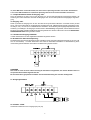
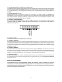
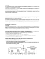
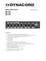
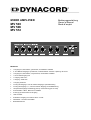
MIXER AMPLIFIER
MV 503
MV 506
MV 512
Bedienungsanleitung
Owner’s Manual
Mode d’emploi
Merkmale:
•
•
1 Eingang für 6,3mm Klinke, symmetrisch, umschaltbar Line/Mikro
•
1 Eingang für 6,3mm Klinke, unsymmetrisch, umschaltbar Line/Mikro
•
1 Cinch-Stereoeingang Line
•
1 Ausgang “PRE OUT”
•
1 Ausgang “TAPE OUT”
•
•
1 Eingang “MAIN IN”
•
•
Vorrang der Eingänge 1, 2, 3 auf die anderen Eingänge, Kontaktaktivierung
•
Summensteller Höhen, Bässe und Lautstärke
•
Schutz gegen Kurzschluss am Ausgang
•
LED-VU-Meter
•
Zusätzlicher Ausgang für Funktion “Music on hold”
•
•
Netzbetrieb 115/230V umschaltbar
2 XLR-Mikrofoneingänge, symmetrisch, mit abschaltbarer “Phantom”-Speisung mit 24V dc.
Vorrang des Eingangs 1 auf die anderen Eingänge, Sprachaktivierung
Lautsprecherausgänge niederohmig (4Ohm) und hochohmig (25-70-100V)
Batteriebetrieb 24V
Inhaltsverzeichnis
Bedienungselemente und Funktionen . . . . . . . . . . . . . . . . . . . . . . . . . . . . . . . . . . . . . .
Frontseite . . . . . . . . . . . . . . . . . . . . . . . . . . . . . . . . . . . . . . . . . . . . . . . . . . . . . . . . . . . .
Rückseite . . . . . . . . . . . . . . . . . . . . . . . . . . . . . . . . . . . . . . . . . . . . . . . . . . . . . . . . . . . .
Speisung mit Wechselstrom . . . . . . . . . . . . . . . . . . . . . . . . . . . . . . . . . . . . . . . . . . . . . .
Speisung mit Gleichstrom. . . . . . . . . . . . . . . . . . . . . . . . . . . . . . . . . . . . . . . . . . . . . . . .
Technische Daten. . . . . . . . . . . . . . . . . . . . . . . . . . . . . . . . . . . . . . . . . . . . . . . . . . . . . .
Anschlußbeispiele . . . . . . . . . . . . . . . . . . . . . . . . . . . . . . . . . . . . . . . . . . . . . . . . . . . . .
Blockdiagramm. . . . . . . . . . . . . . . . . . . . . . . . . . . . . . . . . . . . . . . . . . . . . . . . . . . . . . . .
Garantie . . . . . . . . . . . . . . . . . . . . . . . . . . . . . . . . . . . . . . . . . . . . . . . . . . . . . . . . . . . . .
3
3
4
7
7
8
25
26
28
WICHTIGE SICHERHEITSHINWEISE
Das Blitzsymbol innerhalb eines gleichseitigen
Dreiecks soll den Anwender auf nicht isolierte
Leitungen und Kontakte im Geräteinneren hinweisen, an denen hohe Spannungen anliegen,
die im Fall einer Berührung zu lebensgefährlichen Stromschlägen führen können.
1. Lesen Sie diese Hinweise bitte aufmerksam.
2. Bewahren Sie diese Hinweise auf, so daß Sie diese
gegebenenfalls später nochmals lesen können..
3. Beachten Sie alle Warnhinweise am Gerät und in der
Bedienungsanleitung.
4. Betreiben Sie dieses Gerät nicht in der Nähe von Wasser.
5. Verdecken Sie keine Ventilationsöffnungen.
Installieren Sie das Gerät gemäß den Hinweisen des
Herstellers.
6. Wenden Sie sich bei Reparaturen und Serviceleistungen
an einen qualifizierten Servicetechniker.
2
Das Ausrufezeichen innerhalb eines gleichseitigen Dreiecks soll den Anwender auf wichtige
Bedienungs- sowie Servicehinweise, in der
zum Gerät gehörenden Literatur, aufmerksam
machen.
FRONTSEITE
BEDIENUNGSELEMENTE UND FUNKTIONEN
1. Lautstärkesteller für die Eingänge
Diese Drehknöpfe erlauben die unabhängige Einstellung der Lautstärke der an die Eingänge “IN1", ”IN2", “IN3,
IN4", “AUX IN” angeschlossenen Schallquellen. Durch die Rechtsdrehung jedes Knopfes wird die Lautstärke
erhöht. Es wird empfohlen, den Knopf auf 0 zu stellen, wenn der betreffende Eingang nicht verwendet wird.
2. Summen-Klangsteller BÄSSE
Der Drehknopf verstärkt die tiefen Frequenzen (Rechtsdrehung) oder schwächt sie ab (Linksdrehung). Wenn sich
der Drehknopf in der Mittelstellung befindet, wird der Frequenzgang nicht beeinflußt.
3. Summen-Klangsteller HÖHEN
Der Drehknopf verstärkt die hohen Frequenzen (Rechtsdrehung) oder schwächt sie ab (Linksdrehung). Wenn sich
der Drehknopf in der Mittelstellung befindet, wird der Frequenzgang nicht beeinflußt.
4. Summen-Lautstärkesteller MASTER
Der Drehknopf dient zur Einstellung der Lautstärke am Lautsprecherausgang “OUTPUT” .
Es wird empfohlen, extreme Einstellungen zu vermeiden, bei denen die allgemeine Lautstärke auf das Maximum
und die Bedienungselemente der einzelnen Eingänge auf das Minimum gestellt sind, oder umgekehrt.
5. Kontrolleuchte ON
Die Kontrolleuchte leuchtet auf, wenn der Verstärker eingeschaltet ist.
6. Schalter “POWER”
Ein- und Ausschalten des Gerätes.
7. LED-VU-Meter
Zeigt den Signalausgangspegel an. Für eine korrekte Verwendung des Verstärkers ist es wichtig, daß die Lautstärke
so eingestellt wird, daß der Ausgangspegel im Bereich zwischen -20 dB und 0 dB liegt, der von den ersten 5 Leds
angezeigt wird.
Längeres Aufleuchten der letzten 2 Leds (+3dB und +6dB) zeigt an, daß das Ausgangssignal verzerrt ist; die
Lautstärke muß verringert werden.
3
RÜCKSEITE
SICHERUNGSWERTE
8. Sicherung
Bei Defekten oder bei Anschlußspannungswechsel darf das Ersetzen
der Sicherung nur durch einen Fachmann erfolgen.
Der neue Sicherungswert muß per Aufkleber auf der Rückwand
angegeben werden.
9. Umschalter DC - AC
230V
115V
MV 512
2,5A
5A
MV 506
1,6A
3,15A
MV 503
1A
2A
Mit diesem Schalter kann die Batteriespannung Ein-und Ausgeschaltet
werden.
10. Netzspannungs-Umschalter
Das Gerät ist ab Werk auf 230V AC eingestellt. Eine Umschaltung auf 115V AC kann mit diesem Schalter
vorgenommen werden. Dazu muß die Abdeckung mit Hilfe eines Schraubendrehers geöffnet werden.
11. Ausgang “TAPE OUT”
Die Steckbuchsen “R” und “L” gestatten die Ansteuerung der Eingänge des rechten (“R”) und linken (“L”) Kanals
eines Aufzeichnungsgerätes mit dem gemischten Signal der an die Verstärkereingänge angeschlossenen Schallquellen. Sie sind für koaxiale Cinch-Verbindungen vorbereitet; das vorhandene Signal ist unsymmetrisch. Die
Eingangsimedanz des Aufzeichnungsgerätes muß über 4,7 kOhm liegen.
12. Eingänge “AUX IN” (INPUT 5)
Die Steckbuchsen “R” und ‘L" gestatten den Eingang des rechten (“R”) und linken (“L”) Kanals einer Audioquelle mit
hochpegeligem Signalausgang (z.B. AM/FM-Empfangsgerät, Kassettenrecorder, CD-Player, usw.). Sie sind für
koaxiale Cinch-Verbindungen und unsymmetrische Signale vorbereitet.
13. Empfindlichkeitsschalter für Eingang “IN 4"
Durch die Schaltung auf “MIC” kann der Eingang “IN4" an ein niederohmiges dynamisches Mikrofon angeschlossen
werden; die Schaltung auf ”LINE" erlaubt den Anschluß des Einganges “IN4" an eine Audioquelle mit hochpegeligern
Signalausgang.
14. Eingang “IN4"
Dieser unsymmetrische Eingang kann für den Anschluß eines dynamischen Mikrofons verwendet werden (30-600
Ohm), oder für eine Audioquelle mit hochpegeligem Signalausgang (z.B. AM/FM-Empfangsgerät, Kassettenrecorder,
CD-Player, usw.).Er ist für 6,3 mm-Klinkenstecker vorbereitet. Zur Einstellung der Eingangsempfindlichkeit ist der
Schalter (13) zu betätigen.
15. Schalter “XLR PHANTOM 24 V”
Auf der Schalterstellung “ON” wird die Phantom"-Speisung mit 24V auf den Pins 2 und 3 der Eingänge “IN2", ”IN3"
(16) eingeschaltet. Dadurch können Kondensatormikrofone angeschlossen werden, für die eine solche Speisung
erforderlich ist. Beim Umschalten sollte die allgemeine Lautstärke auf das Minimum eingestellt sein.
16. Eingänge “IN2" - ”IN3"
An diese symmetrischen Eingänge können dynamische Mikrofone angeschlossen werden (30—.600 ohm), oder
Kondensatormikrofone mit “Phantom”-Speisung von 24V. Sie sind für dreipolige “XLR”-Verbindungen. Die Einschaltung der “Phantom”-Speisung mit 24V erfolgt über den Schalter (15).
HINWEISE
Unsymmetrische Mikrofone dürfen bei eingeschalteter “Phantom’-Speisung nicht angeschlossen werden;
sie könnten sonst beschädigt werden. Das Einstecken und Herausziehen der Mikrofonkabel muß bei
abgeschalteter “Phantom”-Speisung erfolgen. Stellen Sie sicher, daß die “Phantom”-Speisung abgeschaltet
4
ist, wenn Mikrofone verwendet werden, die keine externe Speisung erfordern: die auf den Anschlüssen
2 und 3 der XLR-Steckbuchse vorhandene Spannung könnte sonst schwere Schäden verursachen.
17. Empfindlichkeitsschalter für Eingang “IN1"
Durch die Schaltung auf “MIC” kann an den Eingang “IN1" ein dynamisches Mikrofon angeschlosen werden; die
Schaltung auf “LINE” erlaubt den Anschluß des Einganges “IN1" an eine Audioquelle mit hochpegeligern Signalausgang.
18. Eingang “IN1”
Dieser symmetrische Eingang kann für den Anschluß eines dynamischen Mikrofons verwendet werden (30-600
Ohm), oder einer Audioquelle mit hochpegeligem Signalausgang (z.B. AM/FM-Empfangsgerät, Kassettenrecorder,
CD-Player, usw.). Er ist für 6,3 mm-Klinkenstecker vorbereitet. Zur Einstellung der Eingangsempfindlichkeit ist der
Schalter (17) zu betätigen. Der Eingang ist mit der Funktion “Voice Priority” ausgestattet, welche sämtliche anderen
Eingänge ausschaltet, sobald eine Mikrofonansage ausgestrahlt wird. Diese Funktion kann durch eine DYNACORDKUNDENDIENSTSTELLE ausgeschaltet werden.
19. Steckbuchse Eingang Netzkabel
In diese Steckbuchse muß das mitgelieferte Netzkabel eingesteckt werden.
20. Klemmen für Gleichstromspeisung
Die beiden Klemmen erlauben die Speisung des Verstärkers durch eine externe Gleichstromquelle von 24 VDc (z.B.
eine 24 VDc-Batterie). Auf diese Weise kann das Gerät bei Wechselstromausfällen zur Gewährleistung eines
unterbrechungsfreien Betriebes automatisch mit Gleichstrom gespeist werden.
HINWEISE
Das Gerät ist nicht mit einer Ladevorrichtung für die Batterie ausgestattet, aus diesem Grunde sollte ein
entsprechendes Gerät bereitgestellt werden.
Bei mit Gleichstrom gespeistem Verstärker wird die Nominalleistung um etwa 20% herabgesetzt.
21. Ausgangsklemmen
22. Klemme “COM”
Gemeinsame Klemme für die Ausgänge (23) und (24).
5
23. Ausgangsklemme für zusätzlichen Lautsprecher
An dieser Klemme kann ein kleiner zusätzlicher Lautsprecher angeschlossen werden; dieser wird mit dem gemischten
Signal der Eingänge “IN4" und ”AUX-IN" angesteuert, über den geräteintern vorhandenen zusätzlichen Verstärker
mit 1 W-Nominalleistung. Das Ausgangssignal unterliegt nur der Lautstärkeregulierung der Eingänge “IN4" und
”AUX-IN".
24. Ausgangsklemme “0 dB”
Diese Klemme gibt ein unsymmetrisches Signal aus der Mischung der Eingänge “IN4" und ”AUX-IN" zum
Nominalpegel von 0 dB ab. Sie kann für die Ansteuerung eines Audiogerätes mit einer Eingangsimpedanz über 600
Ohm verwendet werden (zusätzlicher Verstärker, Telefonzentrale, usw.). Das Ausgangssignal unterliegt nur der
Lautstärkeregulierung der Eingänge “IN4" und ”AUX-IN".
25. Klemme “VOICE PRIORITY”
Durch Kurzschließen dieser Klemme mit der Klemme “COM” (z.B. anhand eines elektrischen Kontaktes) werden
die Eingänge “IN4" und ”AUX IN" ausgeblendet (keine Signalausstrahlung) und den Eingängen “INI”, “IN2" und
“IN3" der Vorrang gelassen.
26. Klemme “COM”
Gemeinsame Klemme für die Ausgänge (25), (27) und (28).
27. Klemme “PRE OUT”
Diese Klemme gibt das Signal aus der Mischung aller Verstärkereingänge ab. Der Ausgang kann zur Ansteuerung
eines Leistungsverstärkers, eines externen Signalprozessors (z.B. Equalizer) oder eines anderen Gerätes verwendet werden. Das unsymmetrische Signal wird mit den Lautstärkereglern der Eingänge, den Klangreglern und der
Summenregler eingestellt. Zur Verwendung des Ausganges ist die Brücke zu entfernen, die ihn mit dem Eingang
“MAIN IN” verbindet.
28. Klemme “MAIN IN”
Durch das Entfernen der Brücke, die diesen Eingang mit dem Ausgang “PRE OUT” verbindet, kann ein externer
Signalprozessor (z.B. Equalizer) zwischen die Vorverstärkerstufe und die Leistungsstufe des Verstärkers eingeschaltet werden. Diese Lösung eignet sich überall dort wo eine akustische Signalverbesserung (Nachhallbeseitigung,
Equalizer, Larseneffekt-Unterdrückung, usw.) notwendig ist. Der Eingang ist unsymmetrisch.
29. Schraube “GND”
Mit dieser Schraube kann das Chassis des Gerätes geerdet werden, wenn die Steckdose, die für die Stromversorgung verwendet werden soll, keinen Erdungspol besitzt. Der Anschluß darf nur von einem qualifizierten Elektriker
durchgeführt werden.
INSTALLATIONSHINWEISE
Zur Gewährleistung einer ordnungsgemäßen Kühlung der Endstufen, muß der Verstärker an einem gut
belüfteten Ort, vor direkter Sonnenbestrahlung geschützt und von Wärmequellen fern aufgestellt werden.
Vermeiden Sie es, den Lautsprecher an Orten aufzustellen, wo sehr hohe Schwingungen und besonders viel
Staub und Feuchtigkeit vorhanden sind.
6
ACHTUNG
Es wird empfohlen, den Geräteanschluß ausschließlich von qualifizierten Fachkräften vornehmen zu lassen, die
eine ausreichende technische Kenntnis, Erfahrung oder Fachausbildung besitzen um die Anschlüsse richtig
auszuführen und so Stromgefahren vorzubeugen.
Um die Gefahr von Stromschlägen zu vermeiden darf der Verstärker erst nach Beendigung aller Anschlüsse an
das Stromnetz angeschlossen werden.
Vor dem Anschluß an die Netzspannung sind alle Anschlüsse erneut zu kontrollieren und besonders gut zu
überprüfen, daß keine Kurzschlüsse bestehen.
Die gesamte Beschallungsanlage muß in Übereinstimmung mit den für Elektroanlagen gültigen Normen und
Gesetzesvorschriften ausgeführt werden.
SPEISUNG MIT WECHSELSTROM
ACHTUNG
Prüfen Sie vor Inbetriebnahme des Gerätes, daß die Netzspannung der am Spannungswähler (8) eingestellten
Spannung entspricht. Wenden Sie sich andernfalls an Ihren DYNACORD-Händier.
Betreiben Sie das Gerät nur an geerdeten Steckdosen.
Zum Anschluß an das Wechseistromnetz bei 115 oder 230 Vac muß das beigestellte Kabel verwendet werden, das
zuvor an die Steckbuchse (19) des Gerätes angeschlossen werden muß.
Das Gerät ist serienmäßig auf 230V Betriebsspannung eingestellt. Die Umstellung auf 115V darf nur von einem
Fachmann vorgenommen werden. Dazu muß die Abdeckung mit Hilfe eines Schraubendrehers geöffnet werden.
SPEISUNG MIT GLEICHSTROM
ACHTUNG
Zu verwenden sind die Klemmen (20), die sich unter der Schutzabdeckung befinden und an eine Speisequelle von
24VDc (z.B. Batterie) anzuschließen sind. Um Spannungsabfälle auf ein Minimum herabzusetzen und um Überhit2
zungen an den Anschlußkabeln zu verhindern, müssen die Anschlußkabel einen Mindestquerschnitt von 2,5 mm
aufweisen. Die Ein- und Ausschaltung des Gerätes erfolgt über den Schalter (6).
AUSSCHALTEN DES AUTOMATISCHEN VORRANGES FÜR EINGANG “IN1"
Um bei einer Durchsage mit Eingang”IN1" das Abschalten aller anderen Eingänge zu vermeiden, kann
im Geräteinneren eine Umprogrammierung auf Mischbetrieb vorgenommen werden.
1. Abtrennen aller Spannungsquellen vom Gerät.
2. Gerätedeckel mit 3 Schrauben auf jeder Seite lösen und abnehmen.
3. Auf der Eingangsleiterplatte den Stecker CN7/Voice auf “disable” umstecken (siehe Abb.).
4. Gerätedeckel wieder ordnungsgeäß befestigen.
EINSTELLEN DER EMPFINDLICHKEIT FÜR DIE FUNKTION “VOICE PRIORITY”
1. Abtrennen aller Spannungsquellen vom Gerät.
2. Gerätedeckel mit 3 Schrauben auf jeder Seite lösen und abnehmen.
3. Im Geräteinneren ist unterhalb der Bohrung “F” der Eingangsleiterplatte der Trimmwiderstand “VR1"
auf der darunterliegenden Platte angebracht (siehe Abb.).
Mit einem kleinen Schraubendreher kann die Empfindlichkeit durch Rechtsdrehung vergrößert und
durch Linksdrehung verkleinert werden.
4. Gerätedeckel wieder ordnungsgemöß befestigen.
7
TECHNISCHE DATEN MV 503, MV 506, MV 512
Typ
30W - Mono - Tischgerät (MV 503)
60W - Mono - Tischgerät (MV 506)
120W - Mono - Tischgerät (MV 512)
Ausgangsleistung
nominal: 30 W - maximal: 45 W (MV 503)
nominal: 60 W - maximal: 90 W (MV 506)
nominal: 120 W - maximal: 180 W (MV 512)
Nominalleistung bei 24Vdc-Speisung
25W (MV 503) 45W (MV 506) - 95W (MV 512)
Übertragungsbereich
50 - 15.000 Hz ( ± 3 dB)
Verzerrung
≤ 2% (1 kHz - Nominalleistung)
Verhältnis Signal/Geräusch
INPUT 1— 5
Mikro: ≥ 45 dB
Leitung: ≥ 45 dB
MAIN-IN: ≥ 55 dB
Eingänge / Empfindlichkeit - Impedanz
INPUT 1 / 6,3 mm-Klinke / symmetrisch
Mikro: 0,5 mV - 600 Ohm
Leitung: 100 mV - 220 kOhm
INPUT 2-3 (Mikro) / XLR 3-polig/
0,5 mV - 600 Ohm/symmetrisch
INPUT 4 / 6,3 mm-Klinke / unsymmetrisch
Mikro: 0,5 mV - 600 Ohm
Leitung: 100 mV - 220 kOhm
INPUT 5 (Line) / RCA-Stereo /
100 mV - 220 kOhm / unsymmetrisch
MAIN-IN / auf Klemmenbrett / 1 V-10 kOhm
Lautsprecherausgänge/Ohm
4 Ohm
Lautsprecherausgänge/Volt
25V - 70V - 100V (20 Ohm, 170 Ohm, 330 Ohm) (MV 503)
25V - 70V - 100V (10 Ohm, 83 Ohm, 170 Ohm) (MV 506)
25V - 70V - 100V (5 Ohm, 42 Ohm, 83 Ohm) (MV 512)
Zusätzliche Ausgänge/Spannung-Impedanz
PRE-OUT / auf Klemmenbrett / 1 V-10 kOhm /
unsymmetrisch
TAPE-OUT / RCA Stereo / 650 mV-4,7 kOhm /
unsymmetrisch
Ausgänge “Music on hold”
Lautsprecher / Leist.- Imped.: 1 W - 8 Ohm
Leitung 0 dB / Spann.-Imped.: 775 mV-600 Ohm
Klangregelung
Bässe: ± 10 dB - 100 Hz
Höhen: ± 10 dB - 10 kHz
Regler
5 Lautstärkeregler f. Eingänge INPUT 1-5"
1 allgemeiner Lautstärkeregler
1 Klangregler Höhen
1 Klangregler Bässe
Leistungsaufnahme Netzbetrieb
115/230 Vac (±5%) - 50/60 Hz / 90 VA (MV 503)
115/230 Vac (±5%) - 50/60 Hz / 180 VA (MV 506)
115/230 Vac (±5%) - 50/60 Hz / 360 VA (MV 512)
Leistungsaufnahme Batteriebetrieb
(24V)
Abmessungen (BxHxT)
420x88x280 mm
Gewicht
6,9 kg (MV 503) / 7,8 kg (MV 506) / 10 kg (MV 512)
8
2,5 A (MV 503) 4,5 A (MV 506) - 8 A (MV 512)
MIXER AMPLIFIER
Owner’s manual
MV 503
MV 506
MV 512
Description:
•
•
1 balanced 6.3mm input jack, line / micro switchable sensitivity
•
1 unbalanced 6.3mm input jack, line / micro switchable sensitivity
•
1 stereo RCA input, line sensitivity
•
1 “PRE OUT” output
•
•
1 “TAPE OUT” output
•
Input 1 priority on the other inputs with vocal activation
•
•
Input 1, 2, 3 priority on the other inputs, activation with contact
•
Treble, bass and volume controls
•
Protection against short-circuiting between output terminals
•
Vu-meter with LEDs
•
•
Output for “Music on hold” function
•
24V battery power
2 balanced XLR microphone inputs, with excludable 24V dc phantom supply
1 “MAIN IN” input
Outputs for speakers with constant impedance (4ohm) and constant voltage (25-70-100V)
115/230 V mains supply, switchable
9
CONTENTS
Controls and Functions . . . . . . . . . . . . . . . . . . . . . . . . . . . . . . . . . . . . . . . . . . . . . . . . .
Front panel . . . . . . . . . . . . . . . . . . . . . . . . . . . . . . . . . . . . . . . . . . . . . . . . . . . . . . . . . . .
Rear panel . . . . . . . . . . . . . . . . . . . . . . . . . . . . . . . . . . . . . . . . . . . . . . . . . . . . . . . . . . .
AC Power supply . . . . . . . . . . . . . . . . . . . . . . . . . . . . . . . . . . . . . . . . . . . . . . . . . . . . . .
DC Power supply . . . . . . . . . . . . . . . . . . . . . . . . . . . . . . . . . . . . . . . . . . . . . . . . . . . . . .
Specifications . . . . . . . . . . . . . . . . . . . . . . . . . . . . . . . . . . . . . . . . . . . . . . . . . . . . . . . . .
Connections . . . . . . . . . . . . . . . . . . . . . . . . . . . . . . . . . . . . . . . . . . . . . . . . . . . . . . . . . .
Block diagram . . . . . . . . . . . . . . . . . . . . . . . . . . . . . . . . . . . . . . . . . . . . . . . . . . . . . . . .
Warranty. . . . . . . . . . . . . . . . . . . . . . . . . . . . . . . . . . . . . . . . . . . . . . . . . . . . . . . . . . . .
11
11
12
15
15
16
25
26
28
IMPORTANT SAFETY INSTRUCTIONS
The lightning flash with arrowhead symbol,
within an equilateral triangle is intended to alert
the user to the presence of uninsulated “dangerous voltage” within the product’s enclosure that
may be of sufficient magnitude to constitute a
risk of electric shock to persons.
1.
2.
3.
4.
5.
6.
Read these instructions before installing unit.
Keep these instruction for future reference.
Heed all warnings contained in these instructions.
Do not use this apperatus near water.
Do not block any ventilation openings.
Install in accordance with the manufactures instructions.
Refer all servicing to qualified service personnel.
10
The exclamation point within an equilateral triangle is intended to alert the user to the presence
of important operating and maintance (servicing)
instructions in the literature accompanying the
appliance.
FRONT PANEL
CONTROLS AND FUNCTIONS
1. input level controls
These controls let you individually set the volume of the sound sources that are connected to the “IN 1",
”IN 2", “IN 3", ”IN 4", and “AUX IN”. Turning a control clockwise increases the volume of the
corresponding source. We recommend to leave the controls of momentarily not used inputs at their
minimal setting “0".
2. common BASS-control
When turned clockwise this control enhances the low frequency reproduction, while turning it counterclockwise attenuates the bass frequencies. If the control is set to its center position, the overall frequency
response is not being altered.
3. common TREBLE-control
When turned clockwise this control enhances the high frequency reproduction, while turning it counterclockwise attenuates the treble frequencies. If the control is set to its center position, the overall frequency
response is not being altered.
4. VOLUME-control †MASTER
The setting of this control determines the output level that is present at the loudspeaker OUTPUT. We
recommend to generally adjust the MASTER and the input level controls at mediocre positions. Extreme
settings, where the MASTER is set to maximum output and the input controls are nearly set to their
minimum — or vice versa — are not recommendable.
5. ON-indicator
When switching the amplifier’s power on, this indicator lights.
6. POWER switch
Using the POWER switch lets you turn the mains power on or off.
7. LED VU-Meter instruments
This instrument shows the signal’s output level. For proper operation of the amplifier correct volume setting
is of major importance. The first four LED-segments on the left represent the area between —20 dB and
0 dB, in which the outputted level should be kept.
In case the last two segments on the right (+3 dB and +6 dB) are lit for a longer period of time, this means
that the outgoing signal is driven into clipping, which mostly results in audible distortion. You have to adjust
the volume at a lower setting.
11
REAR PANEL
ADMISSIBLE VALUES (FUSE)
8. fuse
In cases of defects or when the amplifier is going to be used
on a different mains voltage, exchanging the fuse should be
left to experienced service personnel.
A label stating the value of the new fuse has to be attached
to the appliance’s rear panel.
230V
115V
MV 512
2,5A
5A
MV 506
1,6A
3,15A
MV 503
1A
2A
9. DC switch
This switch lets you turn the battery supply on or off.
10. mains supply switch
The amplifier is factory preset to 230 V AC. Changing the mains supply to 115 V AC is performed by the
use of this switch. In doing so you have to first open the cover, using a fitting screw driver.
11. TAPE OUT
Connecting the right channel “R” and the left channel “L” of a tape recorder or cassette deck to the right
channel TAPE OUT “R” and the left channel TAPE OUT “L” connectors on the amplifier provides you with
the opportunity to record the mixed signal of the sound sources that are connected to the amplifier and
playing. The TAPE OUT connectors are carried out as RCA-jacks and meant for the connection of
unbalanced sound sources. The input impedance of the connected recording device has to be higher than
4.7 kohms.
12. AUX IN (INPUT 5)
These two RCA-type connectors “R” and “L” let you connect the two channels of an external high-level
unbalanced signal source — such as an AM/FM tuner, a cassette deck, a CD-player, etc..
13. input sensitivity switch (IN 4)
When setting this switch to its “MIC”-position, you can connect a low-impedance dynamic microphone to
the IN 4, while in LINE-setting a high-level source can be connected to the IN 4.
14. input “IN 4"
This unbalanced input lets you either connect a low-impedance dynamic microphone (30 - 600 ohms) or
a high-level sound source (e. g. AM/FM tuner, cassette deck, CD-player, etc.). The connector is carried
out as 1/4" phone jack. To adjust the input sensitivity, please use the corresponding switch (13).
15. XLR PHANTOM 24 V switch
When this switch is set to ON, pins 2 and 3 of the inputs “IN 2" and ”IN 3" (16) are phantom-powered with
24 V, providing you with the possibility to connect condenser type microphones that need phantom voltage
for proper operation. When switching the phantom power on or off, please make sure that the MASTER
control is set to its minimum.
16. inputs “IN 2" and ”IN 3"
These two balanced XLR-type inputs are meant for the connection of dynamic microphones (30 - 600
ohms) or condenser type microphones that accept 24 V phantom power. In case you are using the latter,
the necessary phantom power is activated using the corresponding switch (15).
NOTE
Connecting unbalanced microphones to the appliance when the phantom power is switched on
could lead to severe damage on the microphones and is therefore not permissible. It is absolutely
12
mandatory to perform any plugging or unplugging of microphone cables with the phantom power
turned off. Also make sure, that the phantom power is turned off when utilizing microphones that
are not meant to be operated with phantom power. The voltage that is present on pin 2 and pin 3
of the XLR-connector could lead to severe damages on the microphones. When in doubt, please
consult the owner’s manual of the questionable microphone or contact your dealer before you
perform any connections.
17. input sensitivity switch (IN 1)
Setting this switch to its “MIC”-position lets you connect a low-impedance dynamic microphone to the IN
1, while in LINE-setting a high-level sound source can be played via the IN 4.
18. input “IN 1"
This balanced input lets you either connect a low-impedance dynamic microphone (30 - 600 ohms) or a
high-level sound source (e. g. AM/FM tuner, cassette deck, CD-player, etc.). The connector is carried out
as 1/4" phone jack. To adjust the input sensitivity, please use the corresponding switch (17). The input
features the “Voice Priority” function which overrides all other input signals once a microphone message
is send. If you want to have this function disabled, please contact a DYNACORD SERVICE CENTER.
19. mains cord connector
This connector is meant for the connection of the supplied mains cord.
20. binding posts for the DC battery supply
These two binding posts allow the connection of an external 24 V DC power supply ( e. g. a 24 V DC
battery). In this way continuous operation of the amplifier is maintained even during a power outage, since
it is automatically switched to the DC power source.
NOTES
The amplifier is not capable of recharging the connected battery. Thus, it is recommended to have
a suitable device at hand.
When the amplifier is operated on the DC power source, the nominal power handling capacity
drops by approximately 20 %.
21. binding posts
22. binding post “COM”
The common terminal for the outputs (23) and (24).
13
23. binding post for the connection of an additional loudspeaker
This binding post is meant for the connection of a small external loudspeaker that gets driven by an internal
auxiliary power amplifier, providing a nominal output of 1 watt. Only the mixed audio signal coming from
the “IN 4" and the ”AUX IN" are included in the outputted signal. And hence to this fact, the volume is only
controlled by the input controls of these two channels.
24. binding post “0 dB”
At this terminal the unbalanced mixed audio signal coming from the inputs “IN 4" and ”AUX IN" is outputted
with a nominal level of 0 dB, which can be used to drive an external device that provides a higher input
impedance than 600 ohms (e. g. an additional amplifier, the main telephone or intercom switchboard,
etc.). The volume of the outputted signal is only controlled by the input controls of the “IN 4" and the ”AUX
IN".
25. binding post “VOICE PRIORITY”
When short-circuiting this terminal with the “COM”-terminal (i. e. by means of using an electrical switch),
the audio signals coming from “IN 4" and ”AUX IN" are attenuated while the signals coming from “IN 1",
”IN 2" and “IN 3" are gaining priority.
26. binding post “COM”
The common terminal for the outputs (25), (26) and (28).
27. binding post “PRE OUT”
This terminal outputs the mixed audio signals of all sources that are connected to the amplifier’s inputs
and can be utilized to feed an external power amplifier, a signal processor (e. g. an equalizer), or any
other external appliance. The unbalanced signal is affected by the individual input controls, the sound
balance controls, and the master volume control. Before using the PRE OUT you have to remove the
bridging-strip between this binding post and the “MAIN IN” terminal (28).
28. binding post “MAIN IN”
After removing the bridging-strip between the “PRE OUT” and the “MAIN IN” terminals you can include
an external signal processor (e. g. an equalizer) in the audio-chain between the pre-amplifier and the
power output stage of the power amplifier. This opportunity provides a proper solution whenever shaping
or improving the audio signal is necessary (adjusting delay times, equalizing, eliminating the Larsen-effect,
etc.). The input is unbalanced.
29. “GND” screw
In case the used mains outlet does not provide a ground conductor, this screw offers the possibility to
ground the amplifiers metal parts. Nevertheless, you should leave this procedure to the experienced,
qualified electrician.
INSTALLATION NOTES
At all times, the amplifier has to be operated under appropriate environmental conditions. This
includes that the operation location provides sufficient ventilation and that the device is not
exposed to direct sunlight or the direct radiation or reflection from any heat source.
Installing the loudspeaker systems choose a location that gets not affected by extreme and/or
constant vibrations or other mechanical oscillation. Also make sure that the speakers are installed
at locations that are free from dust and/or moisture.
14
CAUTION
We strongly recommend that you leave the connection of the appliance to the qualified and experienced
service technician who is specialized in connecting electrical and electronical equipment. Do not take the
risk of electro-shock or shock hazard.
To reduce the risk of electro-shock, all connections have to be accomplished before it is permissible to
connect the amplifier to the mains supply.
Before connecting the appliance to the mains supply, once again make certain that all connections are
carried out correctly and that no short-circuits exist.
The overall sound reinforcement installation has to be in accordance to the laws, regulations, standards,
and guidelines that are relevant and applicable in the country where the equipment is going to be operated.
AC POWER SUPPLY
CAUTION
Before using the amplifier for the first time, make sure that the appliance’s mains selector switch (8) is set
in accordance to your mains supply. Otherwise, please consult your DYNACORD dealer.
Connect the amplifier only to grounded mains outlets.
Connecting the amplifier to the mains supply (115 V AC respectively 230 V AC) has to be accomplished
by inserting the supplied mains cord into the corresponding socket (19) and afterwards plugging it into a
mains outlet.
The amplifier is factory preset to be operated on 230 V AC. Changing the mains settings has to be
performed by a qualified service technician, since the device’s outer cover has to be removed using a
suitable screw driver.
DC POWER SUPPLY
CAUTION
A 24 V DC power source (i. e. a battery) has to be connected to the binding posts (20) that are covered
by a protective lid. To reduce the risk of dropping voltage to a minimum and to eliminate the danger of
damaging the battery cables by thermal overload, these cables have to be at least 2,5 mm2 in diameter,
each. Switching the amplifier on or off is performed through the power switch (9).
DISABLING THE AUTOMATIC PRIORITY FUNCTION OF INPUT “IN1"
Internal re-programming for mixing operation avoids all other inputs from being disabled when an annoucement is made through the input “IN1".
1. Disconnect all power sources from the appliance
2. Loosen the 3 screws on each side of the appliance and detach the cover
3. Locate the jumper CN/7 Voice on the INPUT printed board assembly and change it to its “disable”
position (see figure)
4. Re-attach the cover of the appliance
ADJUSTING THE SENSITIVITY LEVEL FOR THE “VOICE PRIORITY” FUNCTION
1. Disconnect all power sources from the appliance
2. Loosen the 3 screws on each side of the appliance and detach the cover
3. Locatehole “F” on the INPUT printed board assembly. The trim potentiometer “VR1" sits on the
printed board assenbly underneath (see figure)
By using a small screw driver to turn the trim potentiometer clockwise, the sensitivity setting is
increased while turning it in the opposite direction decreases the sensitivity.
4. Re-attach the cover of the appliance
15
SPECIFICATIONS MV 503, MV 506, MV 512
Typ
30W - Mono - Tabletop (MV 503)
60W - Mono - Tabletop (MV 506)
120W - Mono - Tabletop (MV 512)
Output power
nominal: 30 W - maximal: 45 W (MV 503)
nominal: 60 W - maximal: 90 W (MV 506)
nominal: 120 W - maximal: 180 W (MV 512)
Nominal power with supply at 24VDc
25W (MV 503) 45W (MV 506) - 95W (MV 512)
Frequency response
50 - 15.000 Hz ( ± 3 dB)
Harmonic distortion
≤ 2% (1 kHz - nominal power)
Signal/Noise Ratio
INPUT 1— 5
Mikro: 3 45 dB
Line: †3 45 dB
MAIN-IN: 3 55 dB
Inputs/Sensitivity - Impedance
INPUT 1 / 6,3 mm- jack / balanced
Mikro: 0,5 mV - 600 Ohm
Line: 100 mV - 220 kOhm
INPUT 2-3 (Mikro) / XLR 3-pins/
0,5 mV - 600 Ohm/ balanced
INPUT 4 / 6,3 mm- jack / unbalanced
Mikro: 0,5 mV - 600 Ohm
Line: 100 mV - 220 kOhm
INPUT 5 (Line) / RCA-Stereo /
100 mV - 220 kOhm / unbalanced
MAIN-IN / on terminal board / 1 V-10 kOhm
Output for speakers / Ohm
4 Ohm
Output for speakers / Volt
25V - 70V - 100V (20 Ohm, 170 Ohm, 330 Ohm) (MV 503)
25V - 70V - 100V (10 Ohm, 83 Ohm, 170 Ohm) (MV 506)
25V - 70V - 100V (5 Ohm, 42 Ohm, 83 Ohm) (MV 512)
Additional outputs / Voltage-Imped.
PRE-OUT / on terminal board/ 1V-10kOhm /
unbalanced
TAPE-OUT / RCA Stereo / 650 mV-4,7 kOhm /
unbalanced
Music on hold outputs
Loudspeaker / Pow.- Imped.: 1 W - 8 Ohm
Line 0 dB / Volt-Imped.: 775 mV-600 Ohm
Tone controls
bass: ± 10 dB - 100 Hz
treble: ± 10 dB - 10 kHz
Controls
5 volume controls for “ INPUT 1-5"
1 general volume control
1 treble control
1 bass control
Power supply / Consumption
115/230 Vac (±5%) - 50/60 Hz / 90 VA (MV 503)
115/230 Vac (±5%) - 50/60 Hz / 180 VA (MV 506)
115/230 Vac (±5%) - 50/60 Hz / 360 VA (MV 512)
Direct current draw (24V)
2,5 A (MV 503) 4,5 A (MV 506) - 8 A (MV 512)
Dimensions (lxhxw)
420x88x280 mm
Weight
6,9 kg (MV 503) / 7,8 kg (MV 506) / 10 kg (MV 512)
16
MIXER AMPLIFIER
Mode d’emploi
MV 503
MV 506
MV 512
DESCRIPTON:
•
1 entrée Jack 6,3 mm symétrique, sensibilité sélectionnable ligne / micro.
•
•
2 entrées microphoniques XLR symétriques, avec alimentation phantom 24 Vdc déconnectable.
•
1 entrée RCA stéréo, sensibilité ligne.
•
1 sortie “PRE OUT”
•
1 sortie “TAPE OUT”
•
1 entrée “MAIN IN”
•
•
Priorité de l’entrée 1 sur les autres entrées à activation vocale.
•
•
Sorties pour enceintes à impédance constante (4 Ohm) et à tension constante (25-70-100V).
•
Protection contre les courts-circuits entre les bornes de sortie.
•
Vumètre à diodes électroluminescentes.
•
Sorties supplémentaires pour foniction “music on hold"
•
Double alimentation en courant alternatif (115/230Vac)
•
Alimentation en courant continu 24 Vdc
1 entrée Jack 6,3 mm asymétrique, sensibilité sélectionnable ligne / micro.
Phorité des entrées 1, 2, 3 sur les autres entrées, activation par contact.
Réglage des tons aigus et graves.
17
Table des matières
Potentiometres et Fonctions . . . . . . . . . . . . . . . . . . . . . . . . . . . . . . . . . . . . . . . . . . . . .
Face Avant . . . . . . . . . . . . . . . . . . . . . . . . . . . . . . . . . . . . . . . . . . . . . . . . . . . . . . . . . . .
Face Arriere . . . . . . . . . . . . . . . . . . . . . . . . . . . . . . . . . . . . . . . . . . . . . . . . . . . . . . . . . .
Alimentation en courant Alternatif (SECTEUR) . . . . . . . . . . . . . . . . . . . . . . . . . . . . . . .
Alimentation en courant Continu (BATTERIE) . . . . . . . . . . . . . . . . . . . . . . . . . . . . . . .
Caractéristiques . . . . . . . . . . . . . . . . . . . . . . . . . . . . . . . . . . . . . . . . . . . . . . . . . . . . . . .
Connections . . . . . . . . . . . . . . . . . . . . . . . . . . . . . . . . . . . . . . . . . . . . . . . . . . . . . . . . . .
Block diagram . . . . . . . . . . . . . . . . . . . . . . . . . . . . . . . . . . . . . . . . . . . . . . . . . . . . . . . .
Warranty. . . . . . . . . . . . . . . . . . . . . . . . . . . . . . . . . . . . . . . . . . . . . . . . . . . . . . . . . . . . .
19
19
20
23
23
24
25
26
28
IMPORTANTES INFORMATIONS DE SÉCURITÉ
Le symbole «éclair» à l’intérieur d’un triangle
signale à l’utilisateur la présence dans l’appareil
de câbles et de contacts qui ne sont pas isolés,
dans lesquels circule un courant électrique à
haute tension, et qu’on ne doit en aucun cas
toucher afin d’éviter de recevoir une décharge
électrique qui pourrait être mortelle.
1. Lisez attentivement ces consignes.
2. Conservez ce manuel afin de pouvoir le réutiliser
ultérieurement.
3. Ne négligez aucunes des consignes de sécurité de
l’appareil et du mode d’emploi.
4. Ne faites pas fonctionner cet appareil à côté d’un point
d’eau.
5. Ne pas obstruer les ouvertures de ventilation.
6. Confiez toute réparation ou travail d’entretien à un
technicien qualifié.
18
Le symbole «point d’exclamation» à l’intérieur
d’un triangle signale à l’utilisateur les consignes
importantes concernant la maintenance et l’emploi de l’appareil, il vous invite à lire le mode
d’emploi accompagnant cet appareil.
FACE AVANT
POTENTIOMETRES ET FONCTIONS
1. Potentiomètres de réglage de niveau d’entrée
Ces potentiomètres vous permettent de régler séparément le niveau des sources sonores reliées aux
prises “IN 1", ”IN 2", “IN 3", ”IN 4" et “AUX IN”. Pour augmenter le niveau d’une source sonore, il suffit de
faire tourner son potentiomètre dans le sens des aiguilles d’une montre. Nous vous recommandons de
laisser sur ”0” les potentiomètres correspondant à des sources momentanément inutilisées.
2. Potentiomètre BASS commun
Lorsqu’il est tourné dans le sens des aiguilles d’une montre, ce potentiomètre augmente le niveau des
fréquences basses ; il les atténue lorsque vous le tournez dans le sens contraire. S’il se trouve en position
centrale, la réponse en fréquence n’est pas modifiée.
3. Potentiomètre TREBLE commun
Lorsqu’il est tourné dans le sens des aiguilles d’une montre, ce potentiomètre augmente le niveau des
fréquences aiguës ; il les atténue lorsque vous le tournez dans le sens contraire. S’il se trouve en position
centrale, la réponse en fréquence n’est pas modifiée.
4. Potentiomètre MASTER
La position de ce potentiomètre détermine le niveau de la sortie haut-parleur. Nous vous recommandons,
d’une manière générale, de positionner les potentiomètres des entrées et MASTER en position moyenne.
Les ouvrir à fond, tant pour le MASTER que pour les entrées, n’est pas recommandé.
5. Indicateur ON
Cet indicateur s’allume dès que vous mettez l’amplificateur sous tension.
6. Interrupteur POWER
Cet interrupteur permet de mettre l’amplificateur sous ou hors tension.
7. Vumètres à LED
Ce vumètre permet de visualiser le niveau de sortie du signal. Pour une exploitation correcte de
l’amplificateur, il est essentiel de procéder à un réglage de niveau correct. Les quatre premiers segments
de l’échelle de LED représentent la zone comprise entre -20 dB et 0 dB : le niveau du signal devrait se
maintenir dans ces limites.
Si les deux derniers segments de l’échelle (représentant respectivement +3 dB et +6 dB) restent allumés
pendant des durées significatives, cela signifie que le signal de sortie sera quelque peu écrêté, ce qui
provoque l’apparition de distorsions audibles. Il vaut mieux, dans ce cas, régler le niveau plus bas.
19
FACE ARRIERE
8. Fusible
Le remplacement du fusible, que ce soit après une défaillance
ou si vous désirez utiliser l’amplificateur sous une tension
secteur différente, devrait être réalisé par un technicien
expérimenté.
Une fois ce remplacement effectué, il faut apposer sur la face
arrière une étiquette indiquant la valeur du nouveau fusible.
valeurs admissibles (fusible)
230V
115V
MV 512
2,5A
5A
MV 506
1,6A
3,15A
MV 503
1A
2A
9. Commutateur DC
Ce commutateur permet de mettre en/hors service l’alimentation par batterie.
10. Commutateur de tension d’alimentation
Lorsqu’il sort d’usine, l’amplificateur est préréglé pour un courant alternatif (AC) de 230 V. Ce commutateur
permet de le faire passer en 115 V AC : pour effectuer cette opération, il faut d’abord ouvrir le coffret, à
l’aide d’un tournevis adéquat.
11. TAPE OUT
Si vous désirez enregistrer le signal correspondant au mélange des sources sonores arrivant sur
l’amplificateur, il faut relier les prises d’entrée repérées “R” et “L” d’un magnétophone aux connecteurs
respectivement repérés TAPE OUT “R” et TAPE OUT “L” sur l’amplificateur. Les connecteurs TAPE OUT
sont de type cinch (RCA) et sont prévus pour une liaison asymétrique. L’impédance d’entrée du
magnétophone relié devrait être supérieure à 4.7 k_.
12. AUX IN (INPUT 5)
Ces deux connecteurs de type cinch, repérés “R” et “L” vous permettent de faire arriver sur l’amplificateur
les deux canaux d’un appareil externe travaillant au niveau ligne et en asymétrique : tuner AM/FM, platine
cassette, lecteur CD, etc...
13. Sélecteur de sensibilité d’entrée (IN 4)
Pour brancher un microphone dynamique à basse impédance sur l’entrée IN 4, il faut placer ce sélecteur
en position ”MIC” : s’il se trouve en position LINE, l’entrée IN 4 sera compatible avec des niveaux ligne.
14. entrée “IN 4"
Cette entrée asymétrique permet de connecter soit un microphone dynamique basse impédance (30 600 ohms), soit une source sonore à haut niveau (telle que tuner AM/FM, platine cassette, lecteur de CD,
etc.). Le connecteur est de type jack 6,35 mm. Pour régler la sensibilité d’entrée, il faut utiliser le
commutateur correspondant (13).
15. commutateur XLR PHANTOM 24 V
Lorsque ce commutateur se trouve en position ON, une tension d’alimentation fantôme 24 Volts apparaît
entre les broches 2 et 3 des entrées “IN 2" et ”IN 3" (16) : vous pouvez alors brancher sur ces entrées
des micros électrostatiques nécessitant ce type d’alimentation. Assurez-vous que le potentiomètre
MASTER est réglé au minimum avant d’activer ou de désactiver l’alimentation fantôme.
16. entrées “IN 2" et ”IN 3"
Ces deux entrées symétriques au standard XLR sont prévues pour la connexion de microphones
dynamiques (30 - 600 ohms) ou de microphones électrostatiques acceptant une tension fantôme de 24
Volts. Dans ce dernier cas, pour activer l’alimentation fantôme, il suffit d’utiliser l’interrupteur correspondant (15).
20
REMARQUE
Si vous branchez un micro câblé en asymétrique sur une entrée dont l’alimentation fantôme est
activée, vous risquez d’endommager gravement le micro : prudence ! Il est impératif, dès que vous
branchez ou débranchez un micro, de désactiver au préalable l’alimentation fantôme. De même,
vérifiez toujours qu’elle est désactivée avant d’utiliser des micros qui n’en ont pas besoin. La
tension présente entre les broches 2 et 3 du connecteur XLR peut endommager le micro. En cas
de doute, veuillez vous reporter au manuel du microphone posant problème, ou contactez votre
revendeur avant toute connexion.
17. commutateur de sensibilité d’entrée (IN 1)
S’il est en position “MIC”, ce commutateur permet de brancher un micro à basse impédance sur l’entrée
IN 1, alors qu’en position LINE, vous pouvez brancher une source sonore à haut niveau en IN 1.
18. entrée “IN 1"
Cette entrée symétrique permet de connecter soit un microphone dynamique basse impédance (30 - 600
ohms), soit une source sonore à haut niveau (telle que tuner AM/FM, platine cassette, lecteur de CD,
etc.). Le connecteur est de type jack 6,35 mm. Pour régler la sensibilité d’entrée, il faut utiliser le
commutateur correspondant (17). Cette entrée est équipée de la fonction “Voice Priority” qui permet de
passer par-dessus tous les autres signaux d’entrée dès qu’un signal micro est envoyé. Si vous désirez
désactiver cette fonction, il faut contacter un service après-vente DYNACORD.
19. embase pour cordon secteur
Cette embase sert à brancher le cordon secteur.
20. bornes pour alimentation 24 Volts continus
Ces deux bornes permettent de connecter une alimentation continue externe, de tension 24 Volts
(batterie, par exemple). De cette façon, l’amplificateur reste opérationnel, même en cas de coupure
secteur, grâce à un dispositif de commutation automatique.
REMARQUES
Il est impossible de recharger la batterie via l’amplificateur. Prévoyez donc un chargeur annexe.
Lorsque l’amplificateur est alimenté par batterie, sa puissance nominale de sortie est réduite
d’environ 20 %.
21. bornes
21
22. bornes “COM”
Terminal commun des sorties (23) et (24).
23. borne pour la connexion d’un HP supplémentaire
Cette borne sert à relier un petit haut-parleur externe, qui se trouve alors alimenté par un petit amplificateur
de puissance auxiliaire interne, d’une puissance nominale de 1 Watt. Ce signal ne comporte que le
mélange des prises “IN 4" et ”AUX IN". Par conséquent, le niveau d’écoute n’est déterminé que par les
commandes d’entrée de ces deux voies.
24. prise “0 dB”
Cette borne permet de disposer du signal asymétrique de mixage des entrées “IN 4" et ”AUX IN", à un
niveau nominal de 0 dB, qui peut être envoyé vers tout appareil externe d’une impédance d’entrée
supérieure à 600 ohms (par exemple, un amplificateur supplémentaire, un standart téléphonique, une
intercom, etc.). Le niveau de ce signal n’est déterminé que par les commandes d’entrée des voies “IN 4"
et ”AUX IN".
25. prise “VOICE PRIORITY”
Si vous court-circuitez ce terminal avec le terminal “COM” (par le biais d’un commutateur par exemple),
les signaux audio arrivant de “IN 4" et ”AUX IN" seront atténués, et les signaux arrivant de “IN 1", ”IN 2"
et “IN 3" deviendront prioritaires.
26. terminal “COM”
Terminal commun aux sorties (25), (26) et (28).
27. prise “PRE OUT”
Sur cette prise arrive le mélange des signaux audio correspondant à toutes les sources reliées aux
diverses entrées de l’amplificateur - vous pouvez l’utiliser pour l’envoyer vers un amplificateur de
puissance externe, un processeur de signal (égaliseur, par exemple), ou tout autre appareil de votre choix.
Le signal asymétrique voit son niveau modifié en fonction des commandes des entrées, des commandes
de balance et de niveau général. Avant de pouvoir utiliser la sortie PRE OUT, il est nécessaire de démonter
le strap reliant cette borne à la borne “MAIN IN” (28).
28. prise “MAIN IN”
Une fois enlevé le strap reliant les bornes “PRE OUT” et “MAIN IN”, vous pouvez insérer un processeur
de signal externe (exemple : un égaliseur) entre la sortie du préamplificateur et l’entrée de l’amplificateur
de puissance. Cette possibilité est bien pratique dès qu’il faut traiter ou améliorer le signal audio (lui
apporter un retard, l’égaliser, éliminer un éventuel Larsen, etc.). Cette entrée est symétrique.
29. borne “GND”
Dans le cas où la prise secteur alimentant l’appareil n’est pas pourvue d’une prise de terre, cette borne
permet de mettre à la terre les parties métalliques de l’amplificateur. Il vaut mieux laisser cette opération
à un électricien qualifié et expérimenté.
CONSEILS D’INSTALLATION
Dans tous les cas, l’amplificateur doit être exploité dans des conditions et dans un environnement
appropriés. Autrement dit, la ventilation doit être suffisante, et l’appareil ne doit pas être exposé
directement aux rayons du soleil, ni aux radiations directes ou aux réflexions d’une source de
chaleur.
Lors de la mise en place des haut-parleurs, choisissez un emplacement qui ne sera pas affecté
par des vibrations importantes et/ou continues, ou à toute autre oscillation mécanique. Vérifiez
également que les haut-parleurs, une fois installés, sont à l’abri de toute poussière et/ou humidité.
22
ATTENTION
Nous vous recommandons expressément de laisser les branchements de l’appareil à un technicien de
service qualifié et expérimenté, spécialisé dans la connexion d’appareils électriques et électroniques. Ne
prenez pas le risque d’une électrocution ou d’un court-circuit.
Afin de réduire les risques d’électrocution, toutes les connexions doivent être effectuées avant de relier
l’amplificateur au secteur.
Avant de relier l’appareil au secteur, encore une fois vérifiez que toutes les connexions sont correctes,
et qu’il n’existe aucun court-circuit.
Toute l’installation de sonorisation doit être conforme aux lois, normes, standards et recommandations
appropriés et en vigueur dans le pays où l’appareil sera exploité.
ALIMENTATION EN COURANT ALTERNATIF (SECTEUR)
ATTENTION
Avant d’utiliser l’amplificateur pour la première fois, vérifiez que son commutateur de tension d’alimentation (8) est réglé en fonction des caractéristiques de votre tension secteur. Si ce n’est pas le cas, veuillez
consulter votre revendeur DYNACORD.
Ne branchez l’amplificateur que sur des prises secteurs munies d’une terre.
Pour brancher l’amplificateur sur le secteur (115 V AC ou 230 V AC), insérez une extrémité du cordon
secteur dans l’embase correspondante (19), puis branchez l’autre extrémité dans une prise de courant.
À sa sortie d’usine, l’amplificateur est préréglé pour une tension de 230 V AC. Le changement de tension
d’alimentation secteur doit être effectué par un technicien de service après-vente expérimenté, car il faut
ouvrir le coffret de l’appareil avec un tournevis spécifique.
ALIMENTATION EN COURANT CONTINU (BATTERIE)
ATTENTION
La source d’alimentation continue sous 24 Volts (par exemple, une batterie) doit être reliée aux bornes
(20), protégées par un cache. Pour éviter tout risque de chute de tension et éviter d’endommager les fils
de batterie par surcharge thermique, il vaut mieux utiliser des câbles d’une section minimale de 2,5 mm2
La mise sous tension/hors tension de l’amplificateur s’effectue par l’intermédiaire du commutateur (9).
DÉSACTIVER LA FONCTION DE PRIORITÉ AUTOMATIQUE DE L’ENTRÉE “IN1"
La reprogrammation interne des opérations de mixage évite que toutes les autres entrées ne soient
désactivées lorsqu’une annonce est effectuée via l’entrée “IN1".
1. Déconnectez toutes les sources d’alimentation de l’appareil.
2. Desserrez les 3 vis situées de chaque côté de l’appareil pour déposer le couvercle.
3. Repérez le cavalier CN/7 Voice sur le circuit imprimé INPUT et placez-le en position “désactivé”
(voir figure).
4. Remettez en place le couvercle de l’appareil.
RÉGLER LE NIVEAU DE SENSIBILITÉ DE LA FONCTION “VOICE PRIORITY”
1. Déconnectez toutes les sources d’alimentation de l’appareil.
2. Desserrez les 3 vis situées de chaque côté de l’appareil pour déposer le couvercle.
3. Repérez le trou marqué “F” sur le circuit imprimé INPUT. Le potentiomètre de réglage (Trimmer)
“VR1" se trouve sur le circuit imprimé placé en-dessous (voir figure).
Au moyen d’un petit tournevis tourner le potentiomètre de réglage dans le sens des aiguilles d’une
montre, le réglage de sensibilité sera augmenté, dans l’autre sens, il sera diminué.
4. Remettez en place le couvercle de l’appareil.
23
CARACTÉRISTIQUES MV 503, MV 506, MV 512
Type
30W - Mono - Tabletop (MV 503)
60W - Mono - Tabletop (MV 506)
120W - Mono - Tabletop (MV 512)
Puissance de sortie
nominale : 30 W - maximale : 45 W (MV 503)
nominale : 60 W - maximale : 90 W (MV 506)
nominale : 120 W - maximale : 180 W (MV 512)
Puissance nominale sous 24 V
25W (MV 503) 45W (MV 506) - 95W (MV 512)
Réponse en fréquence
50 - 15.000 Hz ( ± 3 dB)
Taux de distorsion par harmoniques
plain 2% (1 kHz - puissance nominale)
Rapport Signal/Bruit
INPUT 1-6
Micro : ≥ 45 dB
Ligne : ≥ 45 dB
MAIN-IN : ≥ 55 dB
Entrées / Sensibilité & Impédance
INPUT 1 / 6,3 mm- jack / symétrique
Micro : 0,5 mV - 600 Ohms
Ligne : 100 mV - 220 kOhms
INPUT 2-3 (Micro) / XLR 3 broches/
0,5 mV - 600 Ohms/ symétrique
INPUT 4 / 6,3 mm- jack / symétrique
Micro : 0,5 mV - 600 Ohms
Ligne : 100 mV - 220 kOhms
INPUT 5 (Ligne) / cinch-Stéréo /
100 mV - 220 kOhms asymétrique
MAIN-IN / sur terminal carte 1 V-1 0 kOhms
Sorties haut-parleurs / Ohms
4 Ohms
Sorties haut-parleurs / Volts
25V - 70V - 100V (20 Ohms, 170 Ohms, 330 Ohms) (MV 503)
25V - 70V - 100V (10 Ohms, 83 Ohms, 170 Ohms) (MV 506)
25V - 70V - 100V (5 Ohms, 42 Ohms, 83 Ohms) (MV 512)
Sorties supplémentaires /
Tension et Impédance
PRE-OUT / sur terminal carte / 1 V-10kOhms
asymétrique
TAPE-OUT / cinch stéréo / 650 mV-4,7 kOhms
asymétrique
Sorties Hold
Haut-parleur / Puissance / Impédance : 1 W - 8 Ohms
Ligne 0 dB / Puissance / Impédance : 775 mV-600 Ohms
Correcteurs de Tonalité
Graves : ± 10 dB - 100 Hz
Aigus : ± 10 dB - 10 kHz
Potentiomètres
5 potentiomètres de niveau pour u INPUT 1-5"
1 potentiomètre de niveau général
1 potentiomètre de graves
1 potentiomètre d’aigus
Alimentation / Consommation
115/230 V AC (±5%) - 50/60 Hz / 90 VA (MV 503)
115/230 VAC (±5%) - 50/60 Hz / 180 VA (MV 506)
115/230 V AC (±5%) - 50/60 H z / 360 VA (MV 512)
Intensité demandée (sous 24V)
2,5 A (MV 503) - 4,5 A (MV 506) - 8 A (MV 512)
Dimenslons (LxHxP)
420 x 88 x 280 mm
Poids
6,9 kg (MV 503) / 7,8 kg (MV 506) / 10 kg (MV 512)
24
25
26
Notes
27
GARANTIE
WARRANTY
GARANTIE
Das Werk leistet Garantie für alle
nachweisbaren Material- und Fertigungsfehler für die Dauer von 12
Monaten ab Verkauf.
Garantieleistungen werden nur
dann anerkannt, wenn gültige, d.h.
vollständig ausgefüllte Garantieunterlagen vorliegen.
Von der Garantie ausgenommen
sind alle Schäden, die durch falsche
oder unsachgemäße Bedienung
verursacht werden. Bei Fremdeingriffen oder eigenmächtigen Änderungen erlischt jeder Garantieanspruch.
The manufacturer’s warranty covers all substantial defects in materials and workmanship for a period
of 12 months from the date of
purchase.
Liability claims are accepted solely,
when a valid – correctly and completely filled out – Warranty Registration form is presented by the original
owner of the product. The warranty
does not cover damage that results
from improper or inadequate treatment or maintenance. In case of
alteration or unauthorized repairs,
the warranty is automatically terminated.
La garantie constructeur couvre
tous les défauts matériels et de
main d’œuvre pour une période de
12 mois à compter de la date
d’achat. La garantie ne sera reconnue que si la Carte de Garantie,
correctement et complètement remplie, est présentée par l’acheteur
d’origine du produit. Les dommages
dus à un mauvais maniement de
l’appareil, à un traitement ou une
maintenance incorrects ou inadéquats ne sont pas garantis. Toute
modification ou intervention effectuée par une personne non qualifiée
entraîne la résiliation automatique
de la garantie.
GmbH • Hirschberger Ring 45 • 94315 Straubing •Telefon (09421) 706-0 •Telefax (09421) 706-265
Änderungen vorbehalten. Subject to change without prior notice. Printed in Germany
14. 02. 98 /
Internet: http:// www.eviaudio.de