1
Blower, DVS Gas (Berkshire, Tree of Life, Prairie, Cedar, 2001 Allegiance)
Part # 99000153
CHECK CONDITION OF SHIPMENT
Upon receipt of this kit, check the condition of the packaging. Damage to the package should be noted on the carrier's freight
receipt. Any damage claims as a result of shipping must be handled through the shipper. Travis Industries will provide assistance
in resolving shipping claims or replacing items not included in the package. Please report any missing items immediately.
COMPATIBILITY
• Lopi Berkshire
• Tree of Life
• Avalon Prairie
• Avalon Cedar
• Lopi Allegiance (2001 model)
ITEMS NEEDED FOR ASSEMBLY
• 11/32” Socket Wrench
• 1/4” Nutdriver
• 1/2” Open End Wrench
PACKING LIST
• Blower Assembly
• Wiring Harness
• Two Nuts and Washers
INSTALLATION
WARNING:
1
• Thermodisk
• Stud Plate
• Two Rubber Grommets (with spacers)
• Rheostat (with attachment nut & lock washer)
• Rheostat Knob
INSTRUCTIONS
Turn the gas control valve to off and make sure the appliance has fully cooled prior to
conducting service.
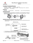
Attach the two black wires on the included wiring harness to the thermodisk (orientation does not matter). Then slide
the thermodisk into the holder underneath the burner pan at the right rear of the stove.
All Models
Except the
Tree of Life and
of
ck
a
B
ve
Sto
2007 Berkshire
Snap Disk Bracket
(attached to stove)
Snap Disk
Snap Disk Wires on Wiring Harness
(Black - orientation does not matter)
a
ve
Tree of Life
f
ko
Remove the snap disk cover plate below
the burner on the left side (when facing
the stove from the front).
b
Attach the snap disk
using the screws
removed in step "a".
Sto
c
Ba
and
2007 Berkshire
c
Page 1 of 4
Attach the wires
labeled snap disk to
the snap disk.
Snap Disk Wires
(Black - orientation
does not matter)
4070219
Blower, DVS Gas (Berkshire, Tree of Life, Prairie, Cedar, 2001 Allegiance)
2
Part # 99000153
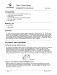
Place the blower near the rear of the stove. Attach the wiring in grommets following the directions below.
Remove one of the screws holding
a
the mounting bracket in place. Insert
the screw through the eyelet on the
green ground wire and replace.
of
ck
a
B
ve
o
t
S
1/4" Nutdriver
b
Attach the black and white wires
labeled “Blower” to the blower
(orientation does not matter).
f
Route the wires labeled “Valve
on/off” and “Solenoid” under
c Attach the molex connector.
the burner pan to a location
near the gas control valve.
e
Attach the two wires leading
Slide the rubber grommets (with
DO NOT PLUG THE STOVE
from the control box to the two
spacers inserted inside) onto the
IN UNTIL INSTALLATION IS
block wires labeled “Rheostat”.
fan mounting bracket.
COMPLETE.
Page 2 of 4
d
4070219
Blower, DVS Gas (Berkshire, Tree of Life, Prairie, Cedar, 2001 Allegiance)
3
Part # 99000153
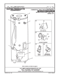
Slide the left side of the blower mounting bracket over the grommets on the left mounting bracket attached to the
stove (see the illustration below). Then insert the stud plate through the right side grommets and through the right
mounting bracket on the stove. Secure the stud plate with the included washers and nuts
Make sure the bracket
Left Mounting
Bracket (on stove)
slides into the groove on
the rubber grommets.
Rubber
Right Mounting
of
k
c
Ba ve
Sto
Bracket (on stove)
Stud Plate
Blower Mounting
Grommet
Bracket
Blower Mounting Bracket
Stud Plate
Blower Mounting Bracket
11/32”
Socket
Washer
Nut
4
Make sure all of the wiring is placed away from the blower impeller and the bottom of the burner. Use lock ties, if
necessary, to ensure no wires are damaged.
Page 3 of 4
4070219
Blower, DVS Gas (Berkshire, Tree of Life, Prairie, Cedar, 2001 Allegiance)
5
Part # 99000153
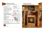
Open the control cover following the directions below. Remove the button plug and install the rheostat.
a
Loosen the two screws holding the control
box in place. This allows access to the
back of the control box.
b
Attach the rheostat wires to the two
quick connects inside the control
box (orientation does not matter).
Control Box
Phillips
Screwdriver
NOTE: make sure the
fiberglass heat shield is in
place when re-attaching the
control box (all models except
the cedar).
c
Rheostat
Attach the rheostat to
the control panel with
the included nut and
star washer.
1/2"
Wrench
Back of
Stove
Attach
the knob.
6
NOTE: this tab fits into the
hole on the mounting bracket.
If using the modulating remote thermostat, attach the red and brown wires to the gas control valve.
Attach the red and
brown wires to the top
and bottom terminals
on the gas control
E
VALVFF”
“ON/O
7
Plug the blower in. Let the heater achieve operating temperature and test blower operation.
Page 4 of 4
4070219