1
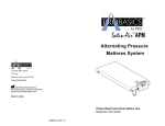
True Low Air Loss Therapy Blower
Replacement Mattress System
Future Air True Low Air Loss
Instruction Manual
99 Seaview Boulevard
Port Washington, NY 11050
Phone: 516-998-4600
Fax: 516-998-4601
Toll Free: 877-224-0946
www.drivemedical.com
Please Read Manual Before Operating Device.
Model No.: 14000PLEASE READ ALL INSTRUCTIONS BEFORE USE.
CONTENTS
IMPORTANT SAFEGUARDS
SAVE THESE INSTRUCTIONS
………………………………………………………………………………………
GROUNDING INSTRUCTIONS
2
1. INTRODUCTION …………………………………………………………………………………………………………..3
1.1 GENERAL INFORMATION ………………………………………………………………………………..3
1.2 INTENDED USE……………………………………………………………………………………………………..3
This product should be grounded. In the event of an electrical short circuit grounding reduces the risk
of electric shock by providing an escape wire for the electric current. This product is equipped with a
cord having a grounding wire with a grounding plug. The plug must be plugged into an outlet that is
properly installed and grounded.
………………………………………………………………………………………..
4
2. PRODUCT DESCRIPTION
2.1 BLOWER& MATTRESS SYSTEM……………………………………………………………………4
2.2 BLOWER UNIT………………………………………………………………………………………………………5
2.3 FRONT PANEL………………………………………………………………………………………………………5
3.INSTALLATION ……………………………………………………………………………………………………………7
…………………………………………………………
3.1 BLOWER& MATTRESS INSTALLATION
7
…………………………………………………………………………………………………………………..
4. OPERATION
9
4.1GENERALOPERATION………………………………………………………………………………………..9
4.2 CPR……………………………………………………………………………….…………………………………………..9
4.3 PRESSURE SET UP…………………………………………………………………………………………..10
4.4 AUDIBLE AND VISIBLE ALARM……………………………………………………………………..10
4.5 ALARM MUTE………………….…………………………………………………………………………………..10
5. CLEANING
……………………………………………………………………………………………………………..…
6. STORAGE
…………………………………………………………………………………………………………………..
If repair or replacement of the cord or plug is necessary, do not connect the grounding wire to either flat
blade terminal. The wire with insulation having an outer surface that is green with or without
yellowstripes is the grounding wire.
NOTE-If the repair or replacement of the cord is necessary, please contact aqualified electrician or
serviceman. To reduce the risk of electric shock, do not modify the cord or plug in any way.
Check with a qualified electrician or serviceman if the grounding instructions are not completely
understood, or if in doubt as to whether the product is properly grounded.
1 YEAR LIMITED WARRANTY
10
11
7. MAINTENANCE ………………………………………………………………………………………………………….11
7.1GENERAL…………………………….……………………………………………………………………………….11
7.2 FUSE REPLACEMENT……………………………………………………………………………………….11
7.3 AIR FILTER REPLACEMENT………………..………………………………………………………….12
7.4 RECHARGEABLE BATTERY…………...……………………………………………………………….12
8. TROUBLESHOOTING…………………………………………………………………………………………….12
9. TECHNICAL DESCRIPTION……………………………………………………………………………………13
SAVE THESE INSTRUCTIONS
DANGER-Improper use of the grounding plug can result in a risk of electric shock.
………………………………………..…………………………………………
Your Drive brand product is warranted to be free of defects in materials and workmanship for one
year of the original consumer purchaser.
This device was built to exacting standards and carefully inspected prior to shipment. This 1 year
Limited Warranty is an expression of our confidence in the materials and
workmanship of our products and our assurance to the consumer of years of dependable service.
This warranty does not cover device failure due to owner misuse or negligence, or normal wear and
tear. The warranty does not extend to non-durable components which are
subject to normal wear and need periodic replacement.
If you have a question about your Drive device or this warranty, please contact an
authorized Drive dealer.
14
1
IMPORTANT SAFEGUARDS
14
READ ALL INSTRUCTIONS BEFORE OPERATING THIS DEVICE.
12
9. TECHNICAL DESCRIPTION
Specifications:
Item
Power
Specification
Supply(Note:
See
rating label on the product)
Fuse Rating
AC 100-120V 50/60 Hz, 5.0A (for 120V system)
AC 220-240V 50/60 Hz, 3A(for 230V system)
T5A/250V(for 120V system)
T3A /250V(for 230V system)
Dimension(LxWxH)
15.8 x 38 x 26.8
Weight
5.5 kg or 12.1 lb
(cm) or 6.2” x 15” x 10.5”
Operation:10° C to 33° C (50° F to 91° F)
Temperature
Storage: -15° C to 50° C (5° F to 122° F)
Shipping: -15° C to 70° C (5° F to 158° F)
Environment
Operation: 10% to 90% non-condensing
Humidity
Storage: 10% to 90% non-condensing
Shipping:10 % to 90% non-condensing
Class I, Type BF, IPX0
Classification
DANGER - To reduce the risk of electrocution:
1. Always unplug this product immediately after using.
2. Do not use while bathing.
3. Do not place or store product where it can fall or be pulled into a tub or sink.
4. Do not place in or drop into water or other liquid.
5. Do not reach for a product that has fallen into water. Unplug immediately.
Applied Part: Air Mattress
Not suitable for use in the presence of a flammable
WARNING - To reduce the risk of burns, electrocution, fire, or injury to persons:
1. This product should never be left unattended when plugged in.
2. Close supervision is necessary when this product is used by, on, or near children or invalids.
3. Use this product only for its intended use as described in this manual. Do not useattachments not
recommended by the manufacturer.
4. Never operate this product if it has a damaged cord or plug, if it is not working properly, if it has been
dropped or damaged, or dropped into water. Return the product to a service center for examination
and repair.
5. Keep the cord away from heated surfaces.
6. Never block the air openings of this product or place it on a soft surface, such as a bed or couch,
where their openings may be blocked. Keep the air opening free of lint, hair, and other similar
particles.
7. Never drop or insert any object into any opening or hose.
8. Connect this product to a properly grounded outlet only. See Grounding Instructions.
anesthetic mixture (No AP or APG protection)
Mattress
Specification
8” Mattress with 10” side bolster
2” foam pocket is provided
Model
Standard (35.4” width)
48” width
Dimension
200 x 90 x 20.3 (25.4)
200 x 122 x 20.3 (25.4) cm or
(LxWxH)
cmor78.7" x 35.4" x 8" (10”)
78.7” x 48” x 8” (10”)
Weight
7.5 kg or 16.5 lb
9.5 kg or 20.9 lb
Maximum Weight Capacity
200kg or 440 lbs
450kg or 1,000lbs
NOTE:Mattress dimension and weight is measured without foam cushion
NOTE, CAUTION AND WARNING STATEMENTS:
NOTE - Indicate some tips.
CAUTION - Indicate correct operating or maintenance procedures in order to prevent damage to or
destruction of the equipment or other property.
WARNING - Calls attention to a potential danger that requires correct procedures or practices in order
to prevent personal injury.
SYMBOLS
Authorised representative in the European community
Manufacturer
"BF"symbol, indicate this product is according to the degree of protecting against
electric shock for type BF equipment
Grounding terminal (for 230V system)
Attention, should read the instructions!
Disposal of Electrical & Electronic Equipment (WEEE):
This product should be handed over to an applicable collection point for the recycling of
electrical and electronic equipment. For more detailed information about the recycling of
this product, please contact your local city office, household waste disposal service or
the retail store where you purchased this product.
2
13
1. INTRODUCTION
11
This manual should be used for initial set up of the system and for reference purposes.
7.3 AIR FILTER REPLACEMENT
1.1 GENERAL INFORMATION
1. Replace the air filter locatedat the bottom of blower.
The system is a true low-air-loss mattress system suitable for prevention and treatment of
2.The filter is reusable and can be washed gentlywith a mild
Pressure Ulcers up through Stage IV.
detergent and water. Dry the filter before use.
The system has been tested and successfully approved with the following standards:
3. Check and replace air filterregularly if environment is dirty.
EN 60601-1
7.4 RECHARGEABLE BATTERY
EN 60601-1-2
EN 55011 Class B
1. To check if the rechargeable battery has been drained out, unplug the power cord andsee if the
IEC61000-3-2
Power Failure indicator will light up along with buzzer last for a few minutes.
IEC 61000-3-3
2. If the Power Failure Alarm is unable to work or the battery might need to be
replaced(approximate life expectancy 6 months),user can contact your dealer or notify the
FOR US AND CANADA ONLY
technician for replacement.
Medical Equipment-Air Blower
8. TROUBLESHOOTING
E228589with respect to electrical shock, fire and
53DGmechanical hazards only in accordance with
Problem
UL60601-1 AND CAN/CSA C22.2 NO.601.1
Power is not ON
Le produit à ététesté avec des équipementsmédicauxetrespecte les normes UL 60601-1 &
Solution
‧ Check if the plug is connected to mains.
‧ Check if there is any blown fuse.
CAN/CSA C22.2 No.601.1. prévenant les choc électrique, le feu et les risques de blessures
physiques.
‧ Check if the Quick Connector is rotated to the Lock/on position.
Alarm is on
1.2 INTENDED USE
(Audible & visual)
This product is intended to help treat and reduce the incidence of pressure ulcers from Stage I –
‧ Check if the power is suddenly shut down.
‧ Check if the connection between air tube connector to blower unit is
tightly secured.
‧ Check if all tubing connections along mattress are secured.
Stage IV, while optimizing patient comfort. It is appropriate for use in home care, long term care
and acute care settings.
‧ Pressure setting might be inadequate for thepatient, adjust comfort
NOTE:Equipment not suitable for use in the presence of a flammable anesthetic mixture
with air or with oxygen or nitrous oxide.
Patient is bottoming out
range 1 to 2 levels higherand wait for a few minutes for best
comfort.
NOTE:L’équipement ne peutêtreutilisés’il y a risque de mélange d’un anesthésique
inflammable avec l’airoul’oxygèneouoxydenitreux.
‧ Check if the fowler boost adaptor is connected and secured to the
Automatic fowler boost is
not functioning
blower unit.
‧ Check if the fowler boost sensor pad tightly snapped to the
designated location inside the bottom of the mattress foam pocket.
If the above information does not solve your problems, please contact your local agent directly.They
3
2. PRODUCT DESCRIPTION
might require a technician totake care the problem.
2.1 BLOWER AND MATTRESS SYSTEM
By wiping the mattress unit with a damp cloth pre-soaked with warm water (not to exceed 65 )
containing a mild detergent, and keep it away from dust. The cover may also be cleaned using
sodium hypochlorite diluted in water. All parts should be air dried thoroughly before use.
CAUTION: Do not use phenolic-based product for cleaning.
CAUTION: After cleaning, dry the mattress without direct exposure of sunlight.
The carrying bag (if available) should be turned inside out and completely wiped down using the
disinfectant solutions. Allow it to air-dry thoroughly. Once the inside is dry, turn it back and wipe
down the outside of the bag with disinfectant solutions.
6. STORAGE
1. To quickly vacuum air out from mattress for storage, rotate the Quick Connector to the CPR
position and press the “Max Firm” button. It will vacuum air out within 5 minutes and then blower
will stop automatically.
2. Disconnect the automatic fowler boost adaptor on the side of the blower unit.
3. Rotate Quick Connector to the “Disconnect” position and pull up the Quick Connector.
4. Lay the mattress out flat and upsides down.
5. Roll from the head end towards the foot end.
6. Foot-end strap can then be stretched around the rolled mattress to prevent unrolling.
7. The power cord could be wrapped around the blower bumper on the back of blower.
CAUTION: When the blower is vacuuming air, air temperature is hot. Do not block the air
outlet.
NOTE: Do not fold, crease or stack the mattresses.
7. MAINTENANCE
7.1 GENERAL
1. Check main power cord and plug, and auto fowler boost cord if there are abrasions or excessive
wears.
2.Check mattress cover for signs of wear or damage. Ensure mattress cover and tubes are
stubbed together correctly.
3. Check the air hoses for any kink or break. For replacement, please contact your local dealers.
7.2 FUSE
REPLACEMENT
1. Quick
Connector
2. BlowerUnit
1.Disconnect the plug form mains power when a blown fuse is
suspected.
4.Auto Fowler Boost Sensor Pad (for standard 35.4” mattress only)
2. Remove the cover of the fuse holder by means ofa small
5. Mattress Foam Pocket
screwdriver.
3.Differential Zone Mattress
2.2 BLOWER UNIT
3.Insert a new fuse of the correct rating in, and replace the
cover of the fuse holder back. The fuse should be rated as
4 120V system) and T3A /250V(for 230V system)
5A/250V(for
type.
9
4.3 PRESSURE SET UP
Users can adjust pressure of air mattress to a desired softness by adjusting the Comfort Level.
Please consult your physician by the below weight support range for a suitable setting.
NOTE:Maximum Weight Capacity : 200kg or 440 lbs (for 35.4”model)
450kg or 1,000lbs (for 48” model)
Front
1. Quick Connector
4.4 AUDIBLE AND VISIBLE ALARM
2. Front Panel
3. Handle
When the following situation occurred, the LED lights will light up along with the buzzer.
4. Auto Fowler Boost Adaptor
4.4.1 CPR – When CPR or quick storage is performed, or the Quick Connector is on Disconnect
position under power on situation, the “CPR” indicator (orange LED) will light up
along with buzzer.
4.4.2 Power Failure – When electrical shortage occurred or power cord is disconnected without
turning off the blower first, the “power failure” indicator (orange LED) will
light up along with buzzer. Check to ensure power cord is connected
properly.
Rear
1. Power Switch
2. Power Socket
3. Fuses
4.4.3 Low pressure – When an abnormal low pressure occurred in body section, the “Low
Pressure” indicator (orange LED) will light up along with buzzer. Check all
tubingsare correctly installed as per installation instructions and ensure
all tubingsare secured properly. The Low Pressure indicator will
continuously light up until the low-pressure fault condition is resolved.
4. Mounting Bracket
5. Blower Bumper
6. Air Filter
4.5 ALARM MUTE
When these situations mentioned above occurred, both the LED light and buzzer will sound off to
warn the patient. By pressing the button, it will temporary mute the buzzer (CPR & Low Pressure)
so the caregiver may check for possible causes. Should the CPR &low pressuresituation not
resolved within 3 minutes, the alarm will resume to beep. When in Power Failure situation,
pressing alarm mute button, it will cease the buzzer and turn off the “power failure” indicator.
2.3 FRONT PANEL
5. CLEANING
By wiping the blower unit with a damp cloth pre-soaked with a mild detergent, and keep it away
from dust. If other detergent is used, choose one that will have no chemical effects on the surface
of the plastic case of the blower unit.
1. ComfortLevel
Comfortlevel controls the air pressure output. When turning up (
), the output pressure will
increase and higherpressure output will support the heavier weight user. Vice versa(
decreasing air pressure.
)for
CAUTION: The Fowler Boost Sensor Pad should be always kept away from water.
CAUTION: Do not immerse or soak blower unit.
NOTE:Maximum Weight Capacity : 200kg or 440 lbs (for 35.4”model)
450kg or 1,000lbs (for 48” model)
5
10
2. Panel Lock
Grounding:
Before any connection to the output connectors is made, the unit shall be connected to a protective
earth conductor via the three-core main cable; the mains plug shall be inserted only into a socket
outlet provided with a protective earth contact. The protective action shall not be negated by the
user of an extension cord without protective conductor.
Several installation tips are listed below:
After installation, the extra length of the power cord, if any, should be neatly arranged to avoid any
tripping accidents. The EQUIPMENT should be firmly placed at position where users/doctors can
access easily.
Should the panel remain untouched for5minutes, the panel lock feature will lock the panel with
green LED light on to prevent accident from changing the setting during normal operation. To
unlock, simply by pressing the Panel Lock button for 3 seconds.
3.Max Firm
This mode will be forced to execute every time the power is turned on. This insures the blower
is able to reach its maximum operating pressure. Once the max pressure level is reached, the
blower will automatically switch into the previous selected comfort level. User can also use this
function as full mattress inflation during patient ingress/egress for better support. There is a 20
minutes auto-recovery mode to return back the previous selected comfort level.
4. OPERATION
4. On/off
NOTE: Always read the operating instruction before use.
Press On to turn on the unit. Press Off to turn off/standby the unit.
NOTE: The power switch on the side of blower must be turned on.
4.1 GENERAL OPERATION
1. Switch on the main power switch found from the side of
the blower and press
on the control panel to turn
on
the power.
2. The system will automatically go into “Max Firm” mode
for a few minutesof inflation.
NOTE: The mattress is equipped with differential
zone feature, therefore center section of
the mattress will be inflated quicker than
the head and foot sections.
3. The low-pressure indicator (orange LED) will light up
when the mattress is not fully inflated.
4. According to the weight and height of the patient, adjust
the pressure setting to the most suitable level without
bottoming out.
5. Fowler Boost
The automatic Fowler Boost featuresadditional supports to the patient during upright position to
prevent bottoming out. This function is automatically activated when the bed is raised and
deactivated when the bed is flat.
NOTE: This function is only available for 35.4” replacement mattress system.
NOTE: When the patient in the raised position, it is recommended that caregiver readjust
the patient sitting posture to prevent possible bottoming out.
6. Alarm Mute
Press alarm mute button to temporary suspend the CPR and low-pressure alarm. Should the
situation not resolved within 3minutes, the alarm shall resume tonotify the patient.
A. CPR
During the CPR situation, the caregiver can rotate the quick connector to perform CPR.
Once the quick connector is switched to CPR mode, CPR alarm will sound with LED light on
to notify the caregiver.
B.PFA (Power Failure Alarm)
During power failure situation, the Power Failure LED light will light on with buzzer. By
pressing the mute button to disable both buzzer and LED.
4.2 CPR
When CPR needs to be performed, quickly rotate the Quick
Connector to the CPR position to release air.
C.Low Pressure Indicator
When low pressure LED continuously lights up with buzzer, the pressure inside of air
mattress body section is abnormal, please check all tubings arecorrectly installed as per
installation instructions and ensure all tubings are secured properly.
NOTE: The low pressure indicator will not be detected if air cells of mattress are purposely
disconnected.
6
3. INSTALLATION
4. Connect and secure the automatic fowler boost adaptor on
Unpacking the box to inspect for any damage, which may have occurred during shipment. If there
are any damages, please contact your dealer immediately.
3.1 BLOWER& MATTRESS INSTALLATION
the side of the blower unit. The automatic fowler boost
sensor pad must snap to the designated location inside the
bottom of the mattress foam pocket.
NOTE: This function is only available for 35.4”
replacement mattress system.
NOTE:
1. Place the mattress on top of the bed frame. Please note for
Use the Velcro strips to fasten the cable of
fowler
the foot end.
boost
sensor
pad
to
prevent
stumbling.
2. Hang the blower onto bed rail (foot-end), and adjust
hangers to best upright position of the blower.
NOTE: Do not place the blower on flat surface, this
might block the air intake of blower unit.
5. Plug the power cord into electrical outlet.
NOTE:1.Make sure the blower unit is suitable for the
local power voltage.
2. The plug is also served to disconnect the
device.
CAUTION:The blower can only be applied to the
mattress recommended by the manufacturer.
Do not use it for any other purpose. (applied
3. Connect air hose connectors from air mattress to the
part: air mattress)
blower unit.Make sure the connector is in the right position
as the inserted diagram below. Rotate the connector
clockwise to the Lock / on position. When a "click" sound is
felt or heard, the connection is completed and secured.
NOTE: The blower is only operable at “Lock/On”
position.
6. Then turn the main power switch to ON position.
7
8