1
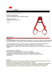
INSTALLATION / OPERATION INSTRUCTIONS WEIGHT DISTRIBUTING HITCH SYSTEMS 7901, 7902, 7903, 7979 (DUAL SWAY CONTROL ATTACHMENT) 7901=600LB WDH KIT, 7902=800LB WDH KIT, 7903=1200LB WDH KIT, 7979=HEAD KIT NOTE: When selecting a shank, select the shortest unit that provides clearance with all the accessories on the tow vehicle and the trailer. This will maximize weight distributing and handling characteristics. DO NOT EXCEED TOWING VEHICLE MANUFACTURER’S LOAD RATINGS SPRING BAR MAX. TONGUE WEIGHT(LB) RATING WHEN USED AS A WEIGHT "600" DISTRIBUTING HITCH WITH SPRING "800" BARS SHOWN: "1200" RATING WHEN USED AS A WEIGHT CARRYING BALL MOUNT WITHOUT SPRING BARS: 7979 MAX. GROSS TRAILER WEIGHT (LB) 600 800 1200 12,000 12,000 12,000 600 6,000 INTRODUCTION When a trailer is hitched to a tow vehicle, the tongue weight typically causes the rear of the tow vehicle to lower and the front to raise. See Figure 1. Figure 1 The purpose of a weight distributing hitch is to remove excessive weight from the tow vehicle’s rear axle and distribute it to the front wheels and the trailer wheels. See Figure 2. Figure 2 SETUP DIMENSIONS 1. Line up tow vehicle and trailer on level pavement, in a straight-ahead position, uncoupled. 2. For vehicles with air springs, air shocks or automatic leveling systems, check vehicle owner's manual. Unless otherwise specified, level the vehicle with the vehicle loaded as it will be when towing. Deactivate load leveling system before coupling trailer and adjusting spring bars. 3. Measure and record uncoupled height on front and rear wheel openings to pavement and level trailer coupler height [See figure 3]. F = _________________ 7900 – 01APR05C PCN7753 Figure 3 R = _________________ 2005 1 H = ___________ TOWING PRODUCTS, INC Litho in USA Figure 4 READ ALL INSTRUCTIONS AND CHECK PACKAGE CONTENTS ASSEMBLE SYSTEM 1. Insert shank into receiver and install pin and clip [See figure 4]. 2. Select hitch ball to match trailer coupler socket, having 1” or 1 - 1/4” threaded shank and capacity equal to or exceeding the gross trailer weight. When using a ball with a 1” shank, bushing (6a) must be used. Attach the ball to the head assembly (2) using a lockwasher and nut. 3. Assemble head to shank as shown in Figure 4. Use (6) hardened washers (6i) over pin (6h) initially. 4. Align head assembly bolt holes to the nearest holes on shank that corresponds to a ball height approximately 1.5 - 2” higher than trailer coupler height ”H”. Leave fasteners loose until hookup has been adjusted. 5. Tighten ball nut according to manufacturer’s specs. Always use a lockwasher. 6. Assemble chains to spring bars as shown in Figure 4. Allow 2 - 3 threads to protrude below locknut [See figure 5]. Chain must not bind. 7. Lower trailer coupler onto hitch ball and close coupler latch. 8. Apply a heavy oil or wheel bearing type grease to the upper and lower trunnion pin of each spring bar assembly. 7900 – 01APR05C PCN7753 2005 2 TOWING PRODUCTS, INC Litho in USA 9. Hold the spring bar (3) perpendicular to the shank (1). Insert the upper trunnion pin into the upper pocket of the head assembly [See figure 6]. Rotate the spring bar so the lower trunnion pin passes through the entrance slot in the lower pocket of the head assembly. Figure 5 Figure 6 Figure 7 10. Position lift units on trailer “A” frame. If trailer tongue consists of a single tube or other narrow member, a pole tongue adapter (Draw-Tite P/N 3280) must be used. Hold spring bar chain vertical. Center lift units with chain [See figure 7]. 11. Turn 1/2-13 x 3-1/2 bolt until it contacts the frame. Then tighten ½ - turn with wrench. DO NOT OVER TIGHTEN. NOTE: Optional mounting holes are provided for trailers that do not permit use of ½ - 13 bolt [See figure 8]. CONSULT TRAILER FRAME MANUFACTURER FOR APPROVAL PRIOR TO DRILLING HOLES. 3/8” hardware is recommended whether it is self-tapping or nut and bolt. OPTIONAL MOUNTING HOLES Figure 8 Figure 9 Figure 10 SPRING BAR CHAIN CONNECTION 1. With lift unit in raised position, pull straight up firmly on spring bar chain. Note which link is closest to chain hook [See figure 7]. Countdown (2) links and that link will used for hook up. NOTE: BEFORE OPERATING LIFT UNIT, RAISE BUMPER OF TOW VEHICLE WITH THE TRAILER TONGUE JACK APPROXIMATELY ONE INCH. THIS WILL REDUCE SPRING BAR TENSION AND MAKE LIFT UNIT OPERATION EASIER. 2. Lower lift unit. Attach upper end of chosen chain link to lift unit hook, while allowing remaining free links to fall down to the outside of the trailer frame (See figure 9). 3. There must be at least 5 links between the lift unit and the spring bar. This is necessary for proper operation of the spring bars during turns (See figure 9). If there will be less than 5 links between the lift unit and spring bar, the angle of the head assembly (2) must be increased. The trailer must be uncoupled and the upper bolt removed from the head assembly. The head assembly is then pivoted down and an additional washer is added underneath the pin [See figure 4]. Reassemble. CAUTION: FAILURE TO CONNECT THE SPRING BAR CHAIN CORRECTLY AND PROVIDE AT LEAST 5 LINKS BETWEEN LIFT UNIT AND SPRING BAR CAN RESULT IN DAMAGE TO THE LIFT UNIT. FIGURE 10 SHOWS INCORRECT SPRING BAR CHAIN HOOK UP. 4. 5. 6. 7. Use handle to raise lift unit. WARNING: Keep clear of all moving parts. Insert spring clip on lift unit. Repeat for opposite spring bar, using same number of links between hook and spring bar. Retract trailer tongue jack so hitch is now carrying the full trailer weight. VEHICLES WITH SELF ADJUSTING AND/OR AUTOMATIC LEVEL CONTROL SUSPENSIONS Some of the newer vehicles may be equipped with some form of automatic leveling system and require special adjustment of the weight distributing system. Please check vehicle owners manual for recommended usage of weight distributing hitches on these vehicles. 7900 – 01APR05C PCN7753 2005 3 TOWING PRODUCTS, INC Litho in USA ADJUST HOOKUP (IF NECESSARY) A weight distributing system is properly set up and coupled when the tow vehicle has settled with the front wheel opening “F” at the original uncoupled dimension measured and slightly lower in the rear ”R”. See Figure 11. • • • • Figure 11 This will assure the front wheel load remains unchanged. This results in good handling and the desired load on the rear axle and trailer axle. The front of the vehicle should never settle more than the rear. See Figure 12. If necessary increase the number of chain links between lift unit and spring bar. If there are no more links, the angle of the head assembly (2) must be decreased. The trailer must be uncoupled and the upper bolt (6e) removed from the head assembly. The head assembly is then pivoted up and a washer (6i) is removed from underneath the pin (6h) [See figure 1]. Reassemble. ¾ - 1 ton and / or long wheelbase vehicles will typically settle with the front wheel opening “F” at the original dimension to 1/2” higher than original. This is will still allow acceptable front wheel loads, good handling and the desired load on the rear axle and trailer axle. If the rear suspension sags too much, additional leveling is required. The front wheel opening “F” may ONLY be settled lower than the original dimension IF the rear wheel opening “R” has settled by a greater amount( At least 1”). Figure 12 1. If additional leveling is required, decrease the number of chain links between lift unit and spring bar. 2. There must be at least 5 links between the lift unit and the spring bar. This is necessary for proper operation of the spring bars during turns. If there are less than 5 links, the angle of the head assembly must be increased. 3. When the desired settling is achieved, mark the hooked chain link with paint for future reference. NOTE: SURGE BRAKES usually require a small amount of fore-aft movement for their actuating mechanisms to function. To avoid restricting movement, it may be necessary to increase the number of chain links between the lift units and the spring bars. CHECK TRAILER AND/OR SURGE BRAKES OPERATING INSTRUCTIONS FOR SPECIAL REQUIREMENTS REGARDING WEIGHT DISTRIBUTING HITCHES. TIGHTEN HEAD FASTENERS 1. Tighten 3/4 bolts and locknuts to 250 lb - ft. Tighten setscrew to 50 lb - ft. CHECK ALL CONNECTIONS BEFORE TOWING 1. Check the following: pin and clip securing shank to receiver, head to shank fasteners, ball nut, coupler latch, lift unit bolt, safety chains, lights and turn signals, and braking system, including breakaway switch. LUBRICATION 1. TRUNNIONS SHOULD BE LUBRICATED EACH TOWING DAY. FAILURE TO DO SO WILL RESULT IN EXCESSIVE POCKET AND TRUNNION WEAR. Use a heavy oil or grease (such as DrawTite Hitch Ball Lubricant P/N 6939). 2. Excessive oil, dirt, and grit should be wiped out of pockets whenever trailer is uncoupled. 3. Clean hitch ball and coupler socket. Coat ball lightly with grease (such as Draw-Tite Hitch Ball Lubricant P/N 6639). 7900 – 01APR05C PCN7753 2005 4 TOWING PRODUCTS, INC Litho in USA WARNINGS FAILURE TO HEED MAY RESULT IN SERIOUS PERSONAL INJURY OR DEATH, VEHICLE CRASH, AND / OR PROPERTY DAMAGE COUPLED BALL HEIGHT SHOULD NEVER BE GREATER THAN UNCOUPLED BALL HEIGHT. Front wheel overload and loss of rear wheel traction can result. This can lead to unstable handling, reduced braking ability, and a tendency to “jackknife” when turning. USE EXTREME CAUTION WHEN BACKING UP AND TURNING. DO NOT ALLOW TOW VEHICLE AND TRAILER TO MANEUVER INTO A “JACKKNIFE” POSITION. Components of the hitch and sway control, if applicable, may be forced into damaging contact. If a “jackknife” maneuver has occurred, examine all towing system components for damage or loosening immediately. Repair or replace any damaged components before resuming towing. DO NOT TOW MULTIPLE TRAILERS. Towing multiple trailers may cause severe instability, loss of control and structural failure. DO NOT ATTEMPT TO HOOK-UP OR TOW WITH A FRONT WHEEL DRIVE VEHICLE WITH THE REAR WHEELS REMOVED. This will cause severe instability, loss of control and structural failure. TOWING TIPS DRIVING - Good habits for normal driving need extra emphasis when towing. The additional weight affects acceleration and braking, and extra time should be allowed for passing, stopping and changing lanes. Signal well before a maneuver to let other drivers know your intentions. Severe bumps and badly undulating road can damage your towing vehicle, hitch, and trailer, and should be negotiated at a slow, steady speed. IF ANY PART OF YOUR TOWING SYSTEM "BOTTOMS OUT", OR IF YOU SUSPECT DAMAGE MAY HAVE OCCURRED IN ANY OTHER WAY, PULL OVER AND MAKE A THOROUGH INSPECTION. CORRECT ANY PROBLEMS BEFORE RESUMING TRAVEL. CHECK YOUR EQUIPMENT Periodically check the condition of all your towing equipment and keep it in top condition. TRAILER LOADING Proper trailer loading is important. Heavy items should be placed close to the floor near the trailer axle. The load should be balanced side-to-side and firmly secured to prevent shifting. Tongue weight should be about 10 - 15 percent of the gross trailer weight for most trailers. Too low a percentage of tongue weight often produces a tendency to sway. SWAY CONTROLS A sway control can help minimize the effects of sudden maneuvers, wind gusts and buffeting caused by other vehicles. Use of a sway control is recommended for trailers with large surface areas, such as travel trailers, and for trailers with low tongue weight percentage. TIRE INFLATION Unless specified otherwise by the towing vehicle or trailer manufacturer, tires should be inflated to their maximum recommended pressure. TOWING VEHICLE AND TRAILER MANUFACTURERS' RECOMMENDATIONS Review the owner’s manual for your towing vehicle and trailer for specific recommendations, capacities, and requirements. PASSENGERS IN TRAILERS Trailers should NOT be occupied while being towed, under any circumstances. TRAILER LIGHT, TURN SIGNALS AND ELECTRIC BRAKES Always hook up trailer lights, turn signals, electric brakes and break-away switch connection (if equipped). Even for short trips. REMOVE HITCH HEAD WHEN NOT TOWING - Remove hitch head from towing vehicle receiver when not towing. This will prevent contamination of head pockets, reduce chance of striking hitch head on driveway ramps or other objects, and minimize damage in event of a rear-end collision. 7900 – 01APR05C PCN7753 2005 5 TOWING PRODUCTS, INC Litho in USA