1
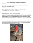
Rebuild kit: Rockauto's Parts Authority MRK12100B which includes Transtec gaskets and ORings, a set of Raybestos metal plates and clutches, and a pretty good filter which is of felt-type, not the strainer that Honda used. Besides that you must buy the spin-on filter plus the three nuts and three washers for the shafts. Those are dealer items and they can be quite expensive (about $9 for a lousy washer). Some observations on the transmission removal: 1. 2. 3. 4. It is imperative to have a good engine hanger like the 1000lbs hanger from Harborfreight. Jack the car up as far as it can go to get clearance to pull the transmission out the front. The entire catalytic converter must be removed to drop the sub-frame. The lower ball-joint is 20mm in diameter while the tool from Harborfreight has a ¾" (19mm) opening. Grind this out to 20mm and you can separate the lower ball-joint from the knuckle. This can also be used to separate the tie-rod from the knuckle without hurting the rubber boots. This is the Harborfreight tool I'm talking about (item#99849). Make sure to put on some ear protection since the bolt separates from the knuckle quite explosively with a loud bang. 5. The front engine mount bracket must be removed just as the manual told you 6. There are 8 bolts holding the transmission to the engine. One of them is the long starter bolt, which is removed first, so you are left with 7 bolts. 7. Dropping the sub-frame with one person is difficult but not impossible (courtesy of HTL Motorsport): a. Put the passenger side lower ball-joint back loosely b. Remove the sub-frame bolts on the passenger side c. Remove the sub-frame bolts on the driver side and lower that side to the ground d. Remove the passenger side ball-joint and lower that side to the ground Rear Main Seal With the transmission out of the way, now is a good time to replace the rear main seal. The engine end cover should be removed so that an O-Ring inside can be replaced at the same time. The part number of the O-Ring is 91308-P3R-T01. The rear main seal can be removed intact with a schedule 40, 3" PVC pipe. We want it intact and undeformed since we will use it as a tool to install the new seal. Clean up the residue of old liquid gasket, but do not install the rear main seal yet. Put in a new O-Ring and re-install the end cover with liquid gasket and without the rear main seal. Don't forget to put liquid gasket on the bottom of the end cover too. I have been using Permatex Grey "Right Stuff" which worked fine for me and is a lot cheaper than Honda's UltraFlange liquid gasket. The engine end cover must be installed without the rear main seal because the oil pan is already in place and there is no room to wiggle the main seal onto the crankshaft without smearing the liquid seal all over the place. At any rate, once the end cover has been installed, the new seal can be installed quite easily. I made all the necessary measurements and here is what I did: 1. Coat the lips of the new seal and the crankshaft with engine oil. 2. Push the new seal in a little bit of the way with your fingers as evenly as you can. 3. Once the new seal has been pushed in a little, install the drive plate on the crankshaft and tighten it all the way in. Tighten the bolts evenly, a little bit at a time until the drive plate is all the way against the crankshaft. This will seat the new seal a little further but not enough. 4. Flip the old seal around and install it onto the crankshaft. It's used like a spacer now. 5. Put the drive plate on the crankshaft backward and tighten the eight bolts all the way. Then remove the drive plate and remove the old seal. Now you can throw away the old seal. Surprisingly, this will seat the new seal to the perfect depth. Warning # 1: The bolts that came with the end cover is of a very strange design with a neck region near the bolt head. This makes it extremely easy to shear the bolts even though I was only applying a torque of 105in–lbs that the manual specified. I got sick in the stomach after one of the bolts sheared off, so I went to Lowes and grabbed a few of those 12.9 grade, 25mm long 6mm socket-head cap-screws and a bunch of 6mm lock-washers. With the lock-washers, the 25mm bolts become the same length as the original screws. However, this means removing the engine end cover and cleaning up the liquid gasket again!!!!! Luckily, the broken bolt has enough protrusion so I could grab it with a small pair of pliers and twist it out quite easily. Warning # 2: Make sure you clean up the bolt holes with a small plastic wire brush since there might be old liquid gasket in there which will collect at the bottom of the blind hole and prevent the bolts from coming in all the way. I just put the plastic wire brush on a drill motor and spin (in reverse) the heck out of it, then blow air into the hole to expel remnants of the liquid gasket. Original Bolt Note the reduced neck Replacement Bolt with lock-washer O-Ring goes here. Use petroleum jelly to "glue" it to the groove. Transmission disassembly End cover 1. Remove, tag and bag all solenoids, switches and sensors from the transmission and then put it face down on a clean table on two blocks of wood to raise it a little bit so that the shaft at the center is not under stress. 2. Remove 16 bolts from the end cover (i.e. the back cover of the transmission) then tap it upward with a small rubber mallet. I guess you can pry it off, but I didn't want to risk damages to the sealing surface. This is the end cover turned upright Pull this straight out Remove bearing and seal This piston can be removed by applying air pressure to this. Be careful, it flies out like a bullet. Remove retainers and pull these pistons off Put some tapes on a pair of pliers and use it as a slide hammer to knock this upward and out 3. Clean all pipes and passages with a plastic wire brush. There is a lot of sludge there. 4. Clean the sealing surface of old gasket material 5. Knockout the bearing and shaft seal, clean the bearing with brake cleaner, reinstall the bearing and put in a new shaft seal. The new shaft seal comes in very easily, you just push it in flush with two fingers. There is no need to drive it in with any driver. 6. Replace all O-Rings, coat everything in ATF, reassemble the end cover, bag it and put it aside. Gears and 3rd Clutch Pack With the end cover removed, it now looks like this Air Pressure to Lock Clutches Secondary Shaft Left Hand Thread Main Shaft Right Hand Thread Slot Counter Shaft Left Hand Thread 3rd Clutch Pack Park Pawl 1. You will need a 34mm socket (which can be borrowed at Autozone) for these nuts 2. The manual calls for chiseling out the retaining tab on the three nuts, but it's much easier to just drive a flat head screwdriver into the slots shown in the picture above. 3. Loosening the nuts: a. The countershaft nut can be opened (clockwise for LH thread) by engaging the parking pawl, which should already be the case if the transmission was in P when it was removed. b. To remove the nuts on the secondary and the main shafts, the manual calls for part number 07GAB-PF50101 which runs about $80. However, you can do without this tool if the clutch packs are still decent. Put air pressure in the main shaft hole in order to loosen the secondary shaft (clockwise). Then put air pressure in the secondary shaft hole to loosen the main shaft nut (counterclockwise). c. You need to buy new nuts and beveled washers, but save the old ones since they are used later to seat the parts 4. Removing 3rd clutch pack requires a special tool and a slide hammer per the manual. However, one can use a small 2-jaw or 3-jaw gear puller like the one below. However, remember to put a small 12mm bolt (that fits nicely in the hole of the counter shaft) to bear against the shaft while you turn the screw on the gear puller. This is what I used. Note the black tape on the jaws to protect the threads on the shaft. I didn't have a 12mm bolt, so I used a 10mm one, but a 12mm would fit better and make the job easier. Once the 3rd clutch pack has been removed, rebuild it per Appendix A. 5. The idler gear and the other two gears can now be removed. Again it requires some "special tools" from Honda, but you can make do with the gear puller borrowed from Autozone (part # 27009 or AZ10). The only problem is that you will need two really long 6mm-1.0mm bolts, about 135mm long. I don't know why Honda must make it so difficult since all other makers used 8mm bolts which are easy to find. At any rate, I don't have anything that long, so I took the two battery retainers and run a 6mm-1.0mm die to thread them all the way to the top as shown below. With a nut and a washer they can substitute for these long bolts. Remove housing With the gears removed we can now remove the housing with these steps: 1. Remove the 10mm bolt on the control shaft, then lift out the spring and the park lever from the control shaft 2. Remove the parking pawl and spring 3. Rotate the control shaft so that the pin on the control shaft aligns with the groove on the housing as shown 4. Remove the two bolts holding the idler gear shaft and remove the shaft. Then use your finger to move the idler gear to the side as shown below. Step 3 Steps 1 & 2 Step 4 Move We are now ready to pull the housing away (up), but then the manual calls for another special tool we don't have. It must be noted that the difficulty does not lie in the three shafts sticking to the bearings. They just slip on, so that should not be a problem. The problem is a whole bunch of tubes that were pressed onto the housing from below. The culprit is this whole bunch of feed tubes shown below after the housing has been removed. To separate the housing, I pried it slightly open first on one place (but not on the sealing surface), then drive a whole bunch of plastic or wood wedges into the crack with a plastic camping mallet (the yellow thing on the table). The door frame shims from Home Depot seem to work well for me. Be patient and don't ruin the sealing surfaces. It helps if you can muster up one or two helpers to lift the housing. Feed Tubes Removing gears and shafts 1. 2. 3. 4. 5. 6. 7. Remove the small bolt in the picture below then pull out the two gears on countershaft Pull out the fork and the associated collar on countershaft Pull out the gears on main shaft Pull out the remaining gears on countershaft Pull out the 4th/5th clutch pack on main shaft and pull out the main shaft Pull out the gears and 1st/2nd clutch pack on the secondary shaft Pull out the secondary shaft, counter shaft, differential and transfer gear shaft Step 1 Step 2 Step 5 Step 4 Step 3 Steps 6 & 7 Transfer gear shaft Differential Remainder Removing valve body Below is a picture of the valve body on the case. The valve body contains some steel balls and springs so we want to remove it in one piece to minimize the chance of losing those. We first remove the fork retainer (two bolts) and the filter (two bolts). Once those are out of the way, remove eight bolts on the pump and carefully lift the pump out of the way to remove the stator. Be careful with a spring, a steel ball and two gears hidden below the pump. Once the stator is out of the way, put the spring and the gears back on the pump and hold them in place with the bolt shown by the blue arrow. Fork retainer Stator Filter Pump After all that, here is a top view. Remove all the bolts except the red ones, and lift the entire valve assembly including the pump off the case. Cleaning the case The case is full of burned fluid, clutch material and 13 years of grime. The first thing you need to do is to clean off the old gasket and remove all the seals. Be patient with this; it took me two full days working the surfaces one inch at a time. It's really painful to work with all the oil and grimes, but it must be done before you clean the case. Once the old gasket is gone, you can either clean the case yourself or just bring it to a transmission shop. They have one of those giant "dishwashers" which clean really well. They charged me $25 which I was happy to pay. After the case came back, spray it really well with non-chlorinated brake cleaner (CRC was on sale at Autozone for $3 a can) and put in new oil seals. Surprisingly, the oil seals I got from the Rockauto rebuild kit appear to be the same as the original seals on the case with the same manufacturer and part numbers. Here is a picture of the back side of the bell housing. It's so clean I am crying tears of joy! Also, while working on other components I always cover it up with a clean plastic trash bag I stole from my wife. Re-Assembly 1. Coat the separator plate with some transmission fluid and put it back on the bell housing with two dowels as shown. Then clean up the accumulator, put in new O-Rings and put it back on the two dowel pins. Note that there are two small stainless balls that are easy to get lost, so be careful and tighten the top plate down well. Dowels 2 steel balls underneath Tighten this well 2. We now tackle the regulator in the picture below. Remove the single bolt that's holding the regulator to the main valve body and gently pull it off. You will see two dowels, but most importantly there will be a spring and a check ball. Do not use a magnet to pull the check ball out. Turn the valve body upside down instead. The red circle is the Torque Converter Check Valve and it is indeed the culprit in most MDX transmission failures. Remove this bolt Spring and check ball Dowels You can now remove the valves from the bores and the filter from the bottom of the regulator. Note which way the filter is installed on the regulator so that you can install the new one in the same direction. The only difficult one is the bore with the big spring. I compress it slightly (about ¼ inch) then remove the retaining bolt and relieve the spring compression to let it out gently as shown in the next pictures. Reassemble and put aside. Filter Remove this bolt The bulge on the screen comes out of the page 3. Next is the top accumulator, which is removed by removing two bolts shown below. Then clean up the valves, the bores, reassemble and put it aside for later. Also shown is one of the valves that could be confusing later, so I took a picture. Remove these bolts Into the bore 4. Next on the list is the servo body shown below, which can be taken off by removing one bolt. Underneath the separator plate is a steel ball and another filter. Note which way the filter goes in and where the steel ball goes. Don't lose that ball. Cleaning and reassembly are the same as usual. The main valve body can be cleaned and reassembled now. Remove this bolt 5. We now reverse what had been done to this point and reinstall the entire valve body on the torque converter housing, but only up to this point where we have to put back the Torque Converter check valve and spring TC check valve and spring Rather than using the OE TC valve and spring, I discard them and order the Sonnax update shown below. There is a very comprehensive instruction that comes with the Sonnax valve, so I won't repeat it here. It may turn out to be snake oil, but we will see. Sonnax sleeve Valve goes inside Spring with check ball underneath After all is said and done, here is the valve body sitting atop Torque Converter housing. Torque spec is 160 in-lbs for the three 8mm bolts and 105 in-lbs for all 6mm bolts. 6. Now put the transfer gear and the differential back on the bell housing as shown below. It goes without saying that you should spray the heck out of them with brake cleaner, blow them dry and put lots of transmission fluid on before putting them back. Actually there is no easy way to clean the differential because the carrier is in one piece, so I suspect a lot of crap remains in there. I don't know what Honda did when they remanufacture these transmissions. Did they put in a new differential? It costs about $400, which is too stiff for me, so I grit my teeth and reuse the old one. The real concern here is that the crap will find its way into the valve body. However, the new filter (the black thingy in the above picture) that came from Rockauto has real felt type filtering material instead of the screen type, so hopefully this won't be too much of a problem. Differential More trash bag stolen from "la femme terrible" Transfer gear 7. Now the counter shaft goes on, but we must disassemble and clean it first and put on two new O-rings. Small circlip Two half clips 8. Now comes the secondary shaft, which can be disassembled for cleaning with one retaining clip. Replace 4 O-rings and 3 metal rings and install. It is worthwhile to note that you are going to need a really good pair of snap-ring pliers. It makes the entire job a whole lot easier. At this point we have only completed the reversal of step 7 on page 8. There is a lot more fun ahead!!! 9. Rebuild the 1st/2nd clutch pack and install on the secondary shaft. The procedure is similar to what we had in appendix A. It's really difficult to install the clutch pack on the shaft since we have to mesh two gears with the clutch plates. Those two gears are shown in the above picture with the red and blue arrows. This is very difficult and frustrating, so I took the shaft back out, assembled the 1st hold clutch pack and put it on the red-arrow gear first. Then I assembled the 1st clutch pack around the blue-arrow gear. The shaft can now be turned around and reinstalled . At the end of the day, you should see a little bit of spline at the top of the secondary shaft as shown below. The remaining gears and bearings can go on the secondary shaft now. At the end, the Torrington bearing should be basically flush with the top step on the shaft as shown. 10. Now put new O-rings and sealing rings on the main shaft and install it in the bell housing. The 4th gear should be on the main shaft at this time. Then rebuild the 4th/5th clutch pack and install it on the main shaft. Since the 4th and 5th clutches are very similar, it can be confusing. The spline end of the clutch pack goes on top. 11. The remainder is just reversing the steps on page 8. At the end, here is the complete assembly before the case goes on. 12. Now is the time to put the other half of the case back on. There are a few things we need to remember: a. Gasket goes on first. It's trivial, but let's not forget. b. There are 3 dowels on the bell housing to retain the gasket. c. Most importantly, put the reverse idler gear on the other half of the case, but not with the shaft. Pull it to the side as shown below; otherwise the upper housing will not come in. Don't forget the thingy under the fork shown in the 1st picture. d. Rotate the control shaft so that the pin on the control shaft aligns with the groove on the housing as shown e. It takes two persons to put the housing back on. Tap it gently with a light rubber or plastic mallet. f. Once the case is fully seated, push the reverse idler gear back in place and install the bearings and the shaft removed earlier, and then just follow the reverse of removal from there. Don't forget this guy Move 13. Now we are ready to torque down the upper housing. There are 20 bolts in five groups of different lengths. For the sake of simplicity I have indexed bolt number 1 by a red circle below and they are to be counted up counter-clockwise. Put the bolts in the following positions, but do not tighten them yet: a. Longest: 7, 8, 10 b. Next: 6, 9, 11 through 14 c. Next: 4, 5, 15 through 18 d. Next: 19 e. Next: 20, 1 through 3 Then put on the three brackets shown in the other three pictures at those bolt numbers. 9, 10 4, 5 12 You can torque the bolts down now. Just go around in small torque increments. The specs are 29ft-lbs for bolts 17, 18, 19 and 33 ft-lbs for all others. 14. Now that the housing is back on, we will reverse steps 1 and 2 on page 7 by putting the parking pawl and the thingy on the control shaft back on. Don't forget the springs. 15. Then the parking gear goes on. Don't hammer it in. Instead, use a spacer and the old nut on the shaft and screw it in tight. 16. The gears on the main shaft and the secondary shaft go on next. Use the old nuts and washer and tighten these to 166 ft-lbs. The thread on the main shaft is right handed and that on the secondary is left handed. 17. The remaining gears on the counter shaft go on next and the 3rd clutch pack goes on after that. Put the old washer and nut back on (left handed) and tighten that to 166 ft-lbs. 18. Now remove the old nuts and washers from all three shafts and discard them. Put in new washers (concave side out towards you) and nuts, then torque them all to 123 ft-lbs. After that, ding the tips of the nuts at the flat spots on the shafts to prevent the nuts from loosening by themselves. 19. Double check, triple check and quadruple check to make sure everything looks like this picture I took right after the end cover came off. O-Rings 20. Put on the three O-rings in the above picture and put the end cover back on. The end is in sight now! There are 16 bolts on the end cover (105 in-lbs) and three brackets as shown: 21. We now put back all the sensors, switches and hoses we removed earlier. I am not doing this in any particular order, just randomly selected parts, one at a time. Also, it's a good idea to test the parts to make sure they are in working order after they are installed. a. Temperature sensor and its harness. I disconnected the connector on the harness and measured the resistance of the sensor. It's 2375, which is good since valid range is 50 – 2500 (Factory Service Manual page 14-74). Also put in the vent hose and the dipstick tube. b. The clutch pressure control solenoids A-B showed a resistance of 5 and they click when 12V is applied, so they still work. Torque is 105 in-lbs for all 6 bolts. Also note the orientation of one bracket on top. After that comes the adapter for the spin on filter along with the ATF Cooler lines, which need two crush washers each (21 ft-lbs). Note the bracket on top with two bolts (20 ft-lbs) and the oil jet. c. The clutch pressure control solenoids C goes on now after testing out OK (5 and click with 12V). d. Now come the Torque Converter Clutch solenoid (black connector) and Shift solenoid valve B (brown connector) on top. Resistance should be 12 – 25 and they should click under 12V. Shift solenoid valves A and C go on next and they are identical to the last two solenoids. My Torque Converter Clutch solenoid went bad, so this is a new one. Speed sensors e. The speed sensors are next. There are two of them and they are identical, so don't worry about which goes where. They cannot be tested unless the shafts are moving, so just probe the resistances between pins and make sure both of them produce similar results, give or take 10%. f. The oil pressure switches go on next. The 4th clutch switch has a brown connector and goes on top. The 3rd clutch switch has a black connector and goes on the bottom with a cover over it. The connector for this switch is also there so plug it in. Torque is 165 in-lbs for both switches. People have recommended replacing these switches, but they can be rather expensive (for me) so I will see how it works out first before springing the money for them. Switches Cover g. The rest is pretty simple. Just a couple of brackets, the Range Switch and its cover. It's all very intuitive and I am getting lazy, so I won't detail it. Here are pictures of the final product. In case you want to put in an external cooler, I also put in the directions of fluid flow, which I decode from the manual. Oil jet fix Installation Before installation I went through and chased all the bolts with a die. You will need 10mm1.25mm and 12mm-1.25mm dies. The threads are aluminum and easy to strip, so don't chase them; instead, clean them with brake cleaner and blow compressed air into the threads to remove all metal bits that came off. You should be warned that all female threads are aluminum and thus inherently weak. Check them carefully and repair with Helicoil, Permacoil, or some similar steel inserts even if you see only a hint of stripped threads. Once the transmission is in, there is very little room to repair these threads and you might have to pull the transmission out again. Then you need to fill the new torque converter with ATF. Even though the torque converter can hold a lot of fluid, I only put in two quarts since I don't want the fluid to spill back out the gaping hole that will mate with the transfer case. That's one bad thing about the 1st generation MDX. For later generations the transfer case and the transmission are completely isolated from each other fluid-wise. The torque converter also has an O-ring, make sure you put it on before installing the torque converter in the transmission. I had a really cheap transmission jack somebody gave me a long time ago, but it can only go up and down. I agonized about it for a long time then broke down and bought a 800lb jack with both pitch and roll from Harborfreight for $120, tax included. Here is the transmission sitting on the jack waiting for installation back in the car. I also took a 1/8"steel flat bar, tap it with 12mm-1.25mm thread and use it to hold the torque converter with a bolt that was cut off to be flush with the bar. This can be removed once the dowels have engaged. To prevent it from falling into the torque converter housing after the dowels engaged, I also put it in a vise and ding the top to make an angle shown in the second picture. Another important thing is to put a little grease on the following places: the stud on the torque converter, the recessed center of the drive plate, the dowels on the engine and the corresponding holes on the transmission. Once all that have been done the transmission can be pushed under the car and raised to mate with the engine. It is necessary to pitch the engine down and the transmission up to avoid hitting the side frame during mating. The transmission jack turned out to be incredible. I have never mated an engine and a transmission so effortlessly. It took all of 5 minutes to line them up and then the transmission can be pushed in gently. It was so smooth I couldn't believe myself. I would never touch another transmission again without this jack from now on. Once the dowels have engaged, put in a couple of bolts loosely and remove the thingy we used to hold the torque converter in place. There are two 10mm bolts and six 12mm bolts. One of the 12mm bolt is really long and will be used for the starter later, so put in only 7 bolts for now. Torque the 10mm bolts to 28 ft-lbs, the two 12mm bolts behind the rear engine mount to 47 ft-lbs and the remaining three 12mm bolts to 40 ft-lbs. Then install the 8 bolts to hold the drive plate to the torque converter at 105 in-lbs. The starter can go on now with 47 ft-lbs on the long bolt and 33 ft-lbs on the short one. We now flush the cooler line inside the radiator. I use an universal flusher shown below, fill it up with hot water since I am weary of putting any solvent in the system, and then shot it through the line with compressed air. Ask an assistant to turn the can upside down to get a two-phase mixture of air and hot water through the line. As the water is being depleted your assistant will have to tilt the can slowly to maintain a two-phase mixture. Do it several times in one direction first and then the other direction until the water comes out clear. Compressed air Shoot through the cooler line After this there will be water in the cooler line that must be removed. I first remove the bumper cover, which is not really a big deal, and install an aftermarket transmission cooler as shown. Then I run an air line through the external cooler and the from the external cooler to one end of the internal cooler line I just flushed. By blowing hot air across the external cooler I can feed hot air into the internal cooler to evaporate the residual water in the line. I ran this for over an hour just to make sure all the water is gone, or so I hope. Even though I drained the radiator, there must be some coolant left at the bottom of the radiator, and all this must be heated up before the water in the cooler line can evaporate. I ran this until the air coming out feels a little warm. It took a long time but it does happen in the end. Compressed air To one end of the internal cooler, the other end is open Hot air blower In the end the external cooler with the Magnefine filter looks like this. Since the bumper cover is out and the power steering is already drained during the removal of the transmission, I put in another Magnefine filter for the P/S in the passenger side bulkhead as shown. Forgot to clip the zip-tie before taking the picture! Now comes the transfer case. The transfer case for the 01-02 MDX shares the same fluid with the transmission, so it is just as filthy inside as the transmission. I was surprised that the service manual made no mention of clearing out the sludge before installation, even though they did go into details on how to flush the cooler line inside the radiator. In my estimate, the transfer case holds a lot more sludge than the cooler line, so this really didn't make any sense. However, I really didn't want to open up the transfer case, so I did the best I could: 1. Make an adapter (just 4 holes on a plate) to fit the output flange of the transfer case with a ½ inch stud at the center and bolt it to the output flange of the transfer case. 2. Turn the transfer case up and fill it with fresh transmission fluid 3. Put the ½ inch stud in an electric drill motor and spin the heck out of it, first in one direction then in the other direction. 4. Turn the transfer case down to drain the fluid from it. 5. Repeat steps 2–4 until no more dark sludge comes out The transfer case can be bolted to the transmission now with eight bolts. Now put everything back the way it was, fill the radiator, P/S and transmission and I am good to go, I guess!!!! Appendix A – Rebuilding 3rd Clutch Pack (Other clutch packs are similar) The manual, once again, calls for a special tool to disassemble the clutch pack. This tool presses down on the spring retainer so that the lock-ring can be removed. I used a home-made tool shown below to do this: 5/16" threaded rod Grind two opposite openings Spring retainer Lock Ring Bottom View Once the spring and retainer, metal plates and clutch plates have been removed, the piston can be removed by turning the clutch upside down and bang it straight down against a wood surface. I just banged it on the table until it comes out partially, then I pull it off. Wash all parts in solvent, and reassemble with new metal and clutch plates. The metal plates measured 1.90mm against a thickness of 1.90mm of the new plates, so they weren't worn out but I replaced them anyways. The clutch plates, on the other hand, were heavily worn, averaging 1.25mm against 1.94mm for the new clutches. I also found that using the new metal and clutch plates from the kit resulted in perfect gap clearance between the retaining ring and the top of the pack (0.7 – 0.9mm).