1
Lotus Service Notes
Section EMN
ENGINE MANAGEMENT & FUEL INJECTION
SECTION EMN - M111 ELISE
Section
Page
Introduction & Component Location
EMN.1
3
'Lotus Check' Scanner Tool
EMN.2
4
Throttle Cable Adjustment
EMN.3
7
Electronic Control Module (ECM)
EMN.4
7
Relay Module
EMN.5
8
Manifold Absolute Pressure (MAP) Sensor
EMN.6
9
Crankshaft Position Sensor
EMN.7
10
Engine Coolant Temperature (ECT) Sensor
EMN.8
11
Intake Air Temperature (IAT) Sensor
EMN.9
12
Throttle Position (TP) Sensor
EMN.10
13
Idle Air Control (IAC) Valve
EMN.11
14
Oxygen (O2) Sensor
EMN.12
15
Camshaft Position Sensor (VVC only)
EMN.13
16
VVC Mechanism Control Solenoids (VVC only)
EMN.14
17
Oil Temperature Sensor (VVC only)
EMN.15
18
Fuel System
EMN.16
19
Ignition System
EMN.17
24
Page 1
Lotus Service Notes
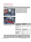
COMPONENT LOCATION DIAGRAM
Page 2
Section EMN
em196
Lotus Service Notes
Section EMN
EMN.1 - INTRODUCTION
Key
1.
2.
3.
4.
5.
6.
7.
8.
9.
10.
11.
12.
13.
to Component Location Diagram
Fuel pump
Engine coolant temperature (ECT) sensor
Water temperature gauge sender (vertical)
Crankshaft position sensor
Oxygen sensor
Intake air temperature (IAT) sensor
Oil temperature sensor (VVC only)
VVC control solenoids
Fuel injector
Fuel pressure regulator valve
Fuel rail
Manifold air pressure (MAP) sensor (VVC only)
Ignition coil (std. and VVC shown)
14.
15.
16.
17.
18.
19.
20.
21.
22.
23.
24.
25.
Cam angle sensor (VVC only)
Idle air control (IAC) valve
Throttle postion (TP) sensor
Throttle body
Relay module
Data link connector (DLC)
Electronic control module (ECM)
Inertia switch
Vehicle speed sensor
Fuel filter
Distributor (std. only)
Evaporative emissions canister
The 1.8 K Series engine fitted to the Elise is equipped with a Modular Engine Management System
(MEMS), version '1.9' for the standard engine, and version '2J' for the VVC engine, abbreviated to 'MEMS 1.9'
or 'MEMS 2J'. Both versions use a single electronic control module (ECM) to control both the fuel injection and
ignition systems, and base the control strategy on engine speed/air density measurement. Engine speed data
is derived from a flywheel sensor, with air density calculated from manifold air pressure and manifold air
temperature signals.
The engine features a throttle body housing a single throttle butterfly valve, with position sensor, feeding
into an intake plenum chamber with four individual intake tracts, each of which is fitted with a fuel injector
positioned to spray fuel onto the back of the intake valves. Standard engines use a lightweight moulded plastic
plenum/manifold, whereas on VVC engines, the manifold is alloy. Fuel delivery quantity is controlled by the
length of time (pulse width) for which the solenoid operated injectors are energised, with the injectors of
standard engines grouped in pairs, 1 with 4, and 2 with 3, whereas the VVC engine uses a fully sequential
strategy with individual control of each injector.
The air/fuel ratio is calculated by the ECM using a three dimensional map to provide a basic fuelling
specification under various operating conditions. In order to refine the fuel delivery and cater for special
conditions, various types of compensation are provided:
Cranking enrichment; During cranking, when engine speed is below about 400 rpm, the injection pulse
width is increased, dependent on coolant temperature, to aid starting.
After start enrichment; Immediately after starting, the pulse width is increased, but decays at a rate
dependent on coolant temperature.
Acceleration enrichment; Signals received from the throttle position and MAP sensors which indicate
acceleration is demanded, will prompt additional fuel for smooth and ready response.
Overrun fuel cut-off; At normal running temperature, when the throttle is closed and engine speed is
above about 2,000 rpm, indicating engine overrun, the fuel supply is shut off to enhance economy and
reduce emissions.
Overspeed fuel cut-off; At a specified engine speed, the injectors are cut off in order to protect the engine
from overspeeding.
Oxygen sensor feedback; By measuring the oxygen content of the exhaust gas, any adjustment necessary to maintain the air/fuel ratio to that required by the catalytic converter for optimum conversion
efficiency may be computed by the ECM. An electrically heated oxygen sensor is used to ensure its
speedy attainment of working temperature after a cold start.
Battery voltage correction; The ECM senses battery voltage, and applies a correction factor to take
account of any variation in fuel delivery due to battery voltage fluctuation.
An idle air control valve mounted on the throttle body, is used to regulate the amount of air by-passing the
throttle plate, and hence control engine idle speed.
Two types of ignition system are used, both controlled by the ECM. Standard engines use a single
ignition coil mounted on the right hand side of the cylinder block, and a distributor driven from the rear end of
the inlet camshaft. VVC engines use a distributorless ignition system (DIS) which employs a pair of double
ended ignition coils and a 'waste spark' system whereby each coil fires two spark plugs simultaneously (1
Page 3
Lotus Service Notes
Section EMN
paired with 4, and 2 with 3), the spark in the cylinder on the exhaust stroke being 'wasted'. The twin coil pack
is mounted on the cylinder block as for standard engines.
On VVC engines, the variable valve control mechanism is also controlled by the ECM. Two solenoid
valves attached to the hydraulic control unit on the inlet camshaft mechanism are used to distribute oil pressure either side of a piston in order to alter the amount of inlet cam cyclical speed variation, and corresponding
valve timing.
The ECM is calibrated to recognise sensor readings which are outside of the acceptable range, and if
such a signal is received from the coolant sensor, inlet air temperature sensor, or MAP sensor, it will substitute
a default value to enable the engine to continue to run, in a 'back up', or 'get you home' mode. As a vehicle
security measure, the engine management ECM incorporates an immobilisation feature, whereby a coded
signal must be received from the security '5AS' module before the starter and ignition circuits become active.
For security details, see electical section MN, or the 'Lotus Check' instruction booklet.
EMN.2 - 'LOTUS CHECK' SCANNER TOOL
In order to provide for communication with the engine management system electronic control module, a
hand held electronic scanner tool, 'Lotus Check' (part number T000T1346), may be plugged into a special 16
terminal harness connector socket, known as a Data Link Connector (DLC), located in the rear luggage compartment.
Cars without 'bootbox' (pre Sept. '98)
'Bootbox' cars (post Sept. '98)
Data
Link
Connector
em194
ohs82
The 'Lotus Check' tool allows the following operations to be performed:
PRE-TEST; This is used to check whether any faults have been detected since the last pre-test.
TEST; This runs a test sequence for various engine management components.
LIVE DATA; This programme enables current readings from various sensors to be displayed or printed.
PROG; Applicable only to VVC models - allows matching of engine and security modules after unit
replacement.
TUNE; Applicable only to VVC models - checks and calibrates certain components.
Contents of the Lotus Check Tool T000T1346
The Lotus Check Tool T000T1346 is supplied in a plastic case, and contains the following items:
Scanner Tool with LCD display panel;
Printer;
Power Harness;
Adaptor Harness;
MEMS 1.9 Programme Card;
MEMS 2J Programme Card;
5AS Security Programme Card;
Security Module ('Dongle');
Instruction Booklet.
Page 4
Lotus Service Notes
Adaptor harness
plugged into DLC
& switched to
'MEMS'
Power
harness
Section EMN
MEMS 1.9
or MEMS 2J
programme
card
Printer
Connect to battery
Scanner tool
em192
To Connect 'Lotus Check'
To connect the equipment, proceed as follows:
i).
Plug the power harness into the scanner tool and the printer;
ii). Insert the MEMS 1.9 (standard engine) or MEMS 2J (VVC engine) programme card into the scanner tool
slot, label uppermost.
iii). Open the front and rear compartment lids;
iv). Connect the power harness crockodile clips to the battery in the front compartment;
v). Plug the adaptor harness into the 16 terminal diagnostic link connector (DLC);
vi). Select 'MEMS' on the adaptor harness switch;
vii). Press F2.
Pre-Test
Whenever the ignition is switched on, or the engine is running, the ECM monitors the readings of all the
sensor inputs, and compares them with pre-programmed tolerance bands. If any readings should fall outside
of these tolerances, the fault will be recorded in memory, and a substitute 'default' value used to enable the
engine to continue to run at a reduced performance level. If the fault is intermittent, and is no longer present
when the ignition is next turned on, the ECM will reinstate the sensor input, but will record the fault in memory.
Dependent on the nature of the fault, this may or may not have been noticed by the driver.
At each maintenance service, the 'Lotus Check' tool should be connected, and the Pre-Test selected from
the main menu to check whether any faults have been detected since the last Pre-Test. This test takes only a
few minutes, during which the scanner display will ask a series of questions and issue instructions to guide the
operator through the test, which is self explanatory, with the following special notes;
'Is fuel rail temperature sensor fitted?' - answer 'NO'.
'How many cooling fans are fitted?' - answer '1'.
References to a 'current clamp' are not applicable in this application - answer 'Proceed'.
After the test has been run, a print out should be obtained as the results are not displayed in any other
manner. If any 'default flags' are shown, the Pre-Test should be run again to establish whether the fault is still
current. If not current (i.e. the fault is intermittent, and is no longer detected), the memory will be cleared of the
default flag, and the next time the test is run, no flag will be shown. Be aware that if a successful repair is
made, the next time a Pre-Test is run, the fault will still be flagged, as having been detected since the previous
Page 5
Lotus Service Notes
Section EMN
test. Run a further test to verify the repair.
Prog
The 'programme' menu is available only on the MEMS 2J card, and allows matching of the engine
management and security 5AS modules if one or the other is replaced. At the instant of ignition is switch on,
the security 5AS module sends a unique coded signal to the engine management ECM, which must be recognised by the ECM before it will allow the engine to run. If no code, or an incorrect code is received, the ECM
will prevent fuelling of the engine, although the engine may crank - typically resulting in engine start followed
immediately by a stall. If either the engine ECM or security 5AS module is replaced, or swopped from another
vehicle, the ECM must be taught to recognise the coded 5AS signal by selecting 'MEMS MATCHING' from the
'PROG' menu and following the instructions.
When mems matching is complete, it is then necessary to select 'CALIBRATION ID' from the 'PROG'
menu to complete the operation - Unless this is performed, the engine will not run.
Note that for standard cars, ECM matching can only be carried out using the '5AS' card and security
password system - refer to service notes sub-section MN.2.
Test
This programme is more comprehensive than the Pre-Test, and takes about 10 minutes to complete tests
on many of the engine management components. During this routine, the scanner display will ask a series of
questions and issue instructions to guide the operator through the test, some parts of which require that the
engine be run up to normal operating temperature. The test should be used any time that a driveability concern
is reported, or if the Pre-Test does not identify the problem.
Components tested in this routine include:
Coolant temperature sensor;
Fuel injectors;
Fuel pump;
Oxygen sensor heater relay;
Purge valve solenoid;
VCC control solenoids (note that it is not normally possible to hear these solenoids operate);
Throttle position sensor;
Cooling fan;
Tachometer;
Idle air control motor;
Oxygen sensor;
The test results should be printed out to identify any detected faults. If a fault is recorded, note that
problem may be in the component or the associated circuitry. Refer to the appropriate EMN sub-section or
circuit diagram to diagnose the fault. Displaying 'Live Data' (see below) may also help diagnosis.
Live Data
This programme, which requires the ignition to be switched on, allows readings from various sensors to
be displayed with or without the engine running. This facility may also be used to observe the sensor readings
whilst the car is being driven, which may help to identify an intermittent problem. Requesting a print, will freeze
the data at that instant and print out a complete list. Comparison of data with a known good car may help to
identify a problem. Erroneous readings may be due to a faulty sensor, or its associated circuitry; refer to the
appropriate EMN sub-section or circuit diagram.
Engine parameters monitored include:
Engine rpm;
Manifold vacuum;
IAC valve position;
Throttle position sensor reading;
Coolant temperature;
Inlet air temperature;
Oxygen sensor voltage.
Tune
The 'test' programme is available only on the MEMS 2J card, and allows the oxygen sensor circuit to be
tested and the IAC valve to be tested and reset without performing a full 'test' programme.
Page 6
Lotus Service Notes
Section EMN
EMN.3 - THROTTLE CABLE ADJUSTMENT
Before adjusting the cable, first check that the pedal end of the cable is correctly located, and that the
cable is correctly routed with no sharp bends or entrapment. Do not attempt to adjust the throttle cable or idle
speed by means of the stop screw on the throttle body, which should not be disturbed.
The throttle cable and associated components must be adjusted in a specific sequence to ensure full and
correct throttle operation without cable strain. The procedure is detailed in sub-section JH.8 but may be
summarised as follows:
Adjust the pedal upstop for a pedal height 30mm below brake and clutch pedals.
Adjust the ball jointed pull rod connecting to the pedal to achieve a gap of 20mm between outer cable
abutment and multiplier lever pivotting link.
Adjust the locknuts at the engine end of the outer cable to allow a small amount of free play to accommodate temperature change effects.
Adjust the pedal downstop so that full travel of the throttle butterfly can just be achieved without allowing
the cable to be strained.
EMN.4 - ELECTRONIC CONTROL MODULE (ECM)
The ECM is an electronic processor mounted on a panel either at the left hand side of the rear luggage
compartment (pre 'bootbox') or at the rear of the engine compartment (with 'bootbox'). The immobilisation
feature of the vehicle security system results in the ECMs for engine management and security being match
coded, such that the engine module must recognise a coded signal from the security module before the unit
becomes operative.
The engine ECM is an adaptive unit which 'learns' the optimum setting of the idle air control valve, and
the fuelling offset required to achieve the correct exhaust oxygen content for a particular engine relative to its
wear and performance characteristics. This feature speeds the response of the system, and minimises the
time spent adjusting to changed operating conditions.
A summary of the sensors supplying inputs to the ECM, and the components to which the ECM supplies
output control, follows:
Inputs
Crankshaft position
Manifold absolute pressure
Engine coolant temperature
Intake air temperature
Exhaust oxygen content
Throttle position
Camshaft position (VVC)
Oil temperature (VVC)
Diagnostic input
Battery supply
Starter signal
Earth supply
Vehicle security signal
ECM
Outputs
Ignition coil
Fuel injectors
Idle air control valve
Fuel pump relay
Diagnostic connector
Oxygen sensor heater relay
VVC control solenoids
Main relay
Radiator cooling fans
Note that the ECM on 'bootbox' cars built between September '98 and February '00 was originally mounted
on the front side of the composite bootbox. In order to improve electromagnetic shielding, a steel mounting
plate was introduced to secure and earth the ECM directly to the rear subframe. All such cars should be retrofitted with this steel mounting bracket.
If a replacement engine ECM is fitted (or security 5AS module), the Lotus Check tool must be used to
match the engine management and security modules. VVC models may use the MEMS 2J card for this
operation (see EMN.2), whereas standard cars must use the security 5AS card and the password system (see
section MN.2.
Page 7
Lotus Service Notes
Section EMN
Before removing an ECM, first disconnect the battery earth lead before pressing the retaining barb and
unplugging the harness connector(s). On standard cars, the MAP sensor is contained within the ECM body,
with the sensor hose connecting to a spigot on the underside of the unit. On pre 'boot box' cars, release the
three screws securing the ECM to the side panel, and withdraw the unit. On post Sept. '98 'bootbox' cars, the
ECM is mounted at the rear of the engine bay, standard modules fixed to the bootbox front wall, and VVC
module using a steel mounting bracket. To release the VVC module, undo the clamp top bolt, the second ECM
top fixing, and lift out the ECM.
Early type mounting
in luggage bay
VVC type
ECM top fixing
ECM
Clamp top fixing
em197
MAP sensor hose
EMN.5 - RELAY MODULE
em222a
The MEMS relay module is single unit serviced only as one component. The unit incorportates the
following relays:
-
Main Relay; Supplies current to the ECM when the ignition is switched on. When the ignition is switched
off, the ECM will keep the main relay energised for a short period whilst the IAC valve is driven to its
power down position, ready for the next engine start.
Fuel Pump Relay; Energised by the ECM for a 3 second period each time the ignition is switched on.
Continuously fed during engine cranking and while the engine is running.
Starter Relay; Energised by the cranking output from the ignition switch. Supplies current to the starter
motor solenoid.
Oxygen Sensor Heater Relay; Energised by the ECM to supply current to the oxygen sensor heating
element.
The unit is mounted adjacent to the engine management ECM, either at the left hand side of the rear
luggage compartment on pre 'bootbox' cars, or, on later cars, at the rear of the engine bay on a tongue fixed to
the rear subframe.
If any of the above functions are faulty, the relay module should be replaced: Pull the module off its
mounting tongue, and release the two harness connector blocks (press the retaining clips). On re-assembly,
ensure the connector blocks are fully engaged by the retaining clips.
Page 8
Lotus Service Notes
em197
Section EMN
Relay
module
em222a
MN.6 - MANIFOLD ABSOLUTE PRESSURE (MAP) SENSOR
The MAP signal is fundamental to the calculation of air consumption and fuel calibration. The ECM
provides a 5 volt supply and earth path to the sensor, which returns a voltage representing the manifold
pressure.
On standard engines, the MAP sensor is contained within the ECM and receives a signal from the intake
plenum ahead of no.1 cylinder intake tract, via a small bore rubber vacuum hose. A liquid trap is incorporated
into this line and is mounted on the right hand side of the engine bay aperture. Faults with the MAP sensor
require that the ECM be replaced.
When using the 'Lotus Check' tool, an atmospheric pressure of approximately 100 KPa should be displayed with the engine stopped, and a lower value between 25 - 40 KPa during idle. Very high values may
indicate a faulty sensor, or a blocked or leaking connecting hose. Moderately raised values indicate a possible
engine fault.
On VVC engined cars, the MAP sensor is mounted directly onto the front end of the intake plenum, and
by avoiding the damping effect of a connecting hose, is able to respond more quickly to changes in plenum
pressure. When replacing the sensor, renew the 'O' ring and tighten the two fixing screws to 9 Nm.
Standard cars:
MAP sensor line liquid trap
em201
VVC cars:
MAP sensor
em220
Page 9
Lotus Service Notes
Section EMN
EMN.7 - CRANKSHAFT POSITION SENSOR
The signals provided by the crankshaft position sensor enable the ECM to determine:
engine speed;
crankshaft position.
The inductive type sensor is mounted by a single fixing into a flange at the right hand rear of the cylinder
block, where it protrudes towards reluctor ring machined into the front face of the flywheel.
-
Single fixing
screw
Crankshaft
position
sensor
em202
The reluctor ring has raised poles at 10° intervals which pass within an air gap of the sensor tip, and
provide a voltage pulsing reference signal used for engine speed calculation. Four missing poles enable the
ECM to determine the crankshaft position in order to correctly time the ignition and fuel injection sequence.
Missing poles are positioned as follows, relative to no.1 cylinder:
Standard
TDC;
50° BTDC;
180° BTDC;
240° BTDC.
VVC
110° BTDC;
150° BTDC;
300° BTDC;
330° BTDC.
Note that on standard engines using grouped injection (1 with 4; 2 with 3), it is not necessary to determine
which cylinders are on the firing, and which on the exhaust stroke. On the VVC engine, using fully sequential
injection, an additional signal from the camshaft position sensor is required to determine the correct injection
and ignition sequence.
To prevent damage from engine overspeed on acceleration, the ECM will implement fuel cut-off at engine speeds above approximately 7,000 rpm by inhibiting the earth path for the injectors. Fuel is progressively
reinstated as engine speed falls.
Faults in the crankshaft sensor or circuit may be indicated on the scanner tool by a '0' display during
cranking. On standard engines, sensor pin no.1 connects to ECM terminal 32 and sensor pin 2 to ECM
terminal 31. Sensor resistance is 1.3 kohms. Fixing screw torque = 6 Nm.
Page 10
Lotus Service Notes
Section EMN
EMN.8 - ENGINE COOLANT TEMPERATURE (ECT) SENSOR
The ECM requires a coolant temperature input signal in order to increase fuel delivery and maintain
driveability during the cold running and warm-up phase. The signal from this sensor is used for many different
parameters within the engine management system to control and switch various components dependent on
engine temperature.
The sensor is a thermistor (a resistor which changes value with temperature) mounted in the outlet
junction pipe at the flywheel end front side of the engine. Note that the ECT sensor has a brown body and
harness connector and is mounted horizontally. This should not be confused with the water temperature gauge
sender which is fitted in the same pipe, but has a blue body and harness connector and is mounted vertically
from below. Low coolant temperature produces a high resistance, whereas high temperature causes low
resistance. At normal running temperature, the resistance will be approximately 300 - 400 ohms.
This data is also used to control the radiator fan, which is switched on by the ECM at a rising coolant
temperature of 102°C, and switched off on falling temperature at 96°C.
Engine Coolant
Temperature
(ECT) sensor
- Brown
Coolant temperature
gauge sender
- Blue
em204
If the ECM receives a signal voltage outside of the acceptable range, a default setting equating to 60°C
will be substituted, and the cooling fan energised.
To replace the sensor, disconnect the harness plug, and position a container to catch the escaping coolant when the sensor is removed. Unscrew the sensor from the junction pipe. Clean the threads of the pipe and
sensor before applying Teflon tape to the sensor thread and screwing into the pipe. Tighten to 6 Nm. Refit the
harness plug, and top up with coolant (see Cooling Section KF).
If the ECM detects a coolant sensor open circuit, a default value of 60°C will be substituted, and will be
displayed on the 'Lotus Check' scanner tool in Live Data. Sensor faults may cause several symptoms including
poor starting, fast idle speed, poor fuel consumption and cooling fans running continuously.
Page 11
Lotus Service Notes
Section EMN
EMN.9 - INTAKE AIR TEMPERATURE (IAT) SENSOR
The intake air temperature (IAT) sensor is fitted into the inlet manifold tract of no.4 cylinder, and is a
transducer with a negative temperature coefficient, such that its electrical resistance reduces with increasing
temperature. Using this signal in conjunction with that from the MAP sensor, the ECM is able to determine the
air consumption of the engine, and adjust the injector pulse width accordingly for correct fuelling. Low air
temperature results in denser air requiring more fuel. High air temperatures are also used by the ECM to retard
the ignition timing and avoid knock.
Inlet Air Temperature
(IAT) sensor
Standard engine
shown
Inlet
manifold
em205
To replace the sensor, unplug the electrical connector, and unscrew the sensor from the manifold. Before
fitting a sensor, clean the threads and mating face, and screw into the manifold, tightening to 7Nm. Mate the
harness plug.
Page 12
Lotus Service Notes
Section EMN
EMN.10 - THROTTLE POSITION (TP) SENSOR
The throttle position (TP) sensor is a potentiometer fitted directly to the end of the throttle spindle, and
provides the ECM with information on both throttle opening, and rate of change of throttle opening. For
example, when a fully closed throttle and appropriate engine speed is signalled, the ECM activates the idle air
control valve to regulate idle speed; a rapid or sudden opening of the throttle will initiate fuel enrichment for
acceleration; and a closed throttle overrun condition will prompt fuel cut-off.
Clamping plate
Throttle Position
(TP) sensor
Torx fixing screw
em198
The ECM provides the sensor with a 5 volt supply, and monitors the returning signal, which is proportional
to throttle opening, on an earth line.
Acceleration enrichment: When the throttle pedal is depressed, the ECM receives a rising voltage from the TP
sensor and detects a rise in manifold pressure from the MAP sensor. The ECM provides additional fuel by
increasing the normal injector pulse width and also provides a small munmer of extra pulses on rapid throttle
openings.
Over-run fuel cut-off: The ECM implements over-run fuel cut-off when the engine speed is above 2000 rpm
with engine at normal operating temperature and the throttle position sensor in the closed position, i.e. the
vehicle is coasting with the throttle released. The ECM indexes the idle air control valve open slightly to
increase the air flow through the engine to maintain a constant manifold depression and keep emissions low.
Fuel is progressively reinstated as the throttle position sensor is opened.
When using the 'Lotus Check' scanner tool, 'Throttle Bits' shows the raw signal received by the ECM from
the TP sensor, and will range from 0 (closed) to 255 (fully open). The full range of values will not be seen in
practice. 'Throttle Switch' indicates whether the ECM detects an open or closed throttle. If the display reads
'ON' when the throttle is closed, the engine will not idle correctly, and the closed throttle position may need to
be reset. Run a 'TUNE' or 'TEST' programme to reset.
To remove the sensor, unplug the harness connector and remove and discard the two Torx screws securing the sensor. Remove the clamping plate and withdraw the sensor from the throttle spindle.
To fit the sensor:
Clean the mating faces of sensor and throttle body, and align the flat of the sensor with the machined flat
on the throttle spindle.
CAUTION: The TP sensor can be easily damaged if carelessly fitted. When pressing the sensor
onto the spindle, use only finger pressure on the centre of the sensor. Do not use the securing
screws to pull the sensor into position.
Press the sensor into position and rotate counterclockwise to align the fixing holes.
CAUTION: Do not rotate the sensor in a clockwise direction, and ensure it is not rotated beyond
its internal stops.
Fit the clamping plate and tighten two new Torx screws. Mate the harness connector plug.
Operate the throttle and check that full travel of the throttle spindle, from fully closed to fully open, is
achieved.
Page 13
Lotus Service Notes
Section EMN
EMN.11 - IDLE AIR CONTROL (IAC) VALVE
The idle air control (IAC) valve is mounted on the intake plenum, and controls an air passage which bypasses the throttle valve. When the pintle of the valve is fully extended, the passage is closed off for a
minimum idle speed, but as the ECM commands the IAC stepper motor to withdraw the pintle, a progressively
greater amount of air is allowed to by-pass the throttle. In this way, the ECM is able to control engine idle speed
independently of the throttle butterfly.
NOTE: The closed setting of the throttle valve is preset during manufacture, and must NOT be adjusted.
During cold starts, the IAC is opened to provide a raised idle speed, dependent on coolant temperature,
with a gradual decay as the engine warms to normal operating temperature. The ECM also uses the fast
response of ignition timing variation to maintain idle stabilisation, such that at idle, the ignition timing will be
constantly changing. When loads are placed onto or removed from the engine, the ECM senses the change in
engine speed and uses both ignition timing and IAC position to control idle speed.
The position of the idle air control valve should be within the range of 20 to 40 steps (as displayed by a
'Lotus Check' scanner) when the engine is idling at normal engine temperature. This ensures that the idle ari
control valve is able to supply varying amounts of by-pass air to compensate for all loads and temperature
conditions. If outside of this range, there is likely to be a mechanical fault, such as an intake manifold air leak.
Using the 'Lotus Check' scanner, 'IDLE HOTDBPOS' indicates the number of IAC valve steps from fully
closed (0) which the ECM has learned as the position required to maintain the specified hot idle speed. 'STEPS'
shows the position of the IAC valve as calculated by the ECM based on the steps moved since the last ignition
switch off. This value will normally be changing during idle as the ECM continuously monitors idle speed.
When the ignition is switched off, the ECM will keep the main relay energised for a short period whilst the IAC
valve is driven to its power down position, ready for the next engine start.
The IAC valve position may be reset using the 'Lotus Check' tool, or, with the ignition on and mobilised,
by pressing the throttle fully and slowly 5 times.
Idle Air Control
(IAC) valve
Hose to intake
side of throttle
plate
Intake plenum chamber
em200
To remove the valve, unplug the harness connector and remove the two Torx screws securing the valve
body to the plenum adaptor. Withdraw the valve and discard the 'O' ring.
To fit the valve:
Ensure the mating faces of the plenum adaptor and valve are clean.
Lubricate a new 'O' ring with silicone grease, and fit to the valve.
Fit the valve into the adaptor, and tighten the two Torx screws to 1.5 Nm.
Mate the electrical connector plug.
Page 14
Lotus Service Notes
Section EMN
EMN.12 - OXYGEN (O2) SENSOR
The MEMS system operates a 'closed loop' fuel control system whereby the output signal from an oxygen
sensor in the exhaust system is monitored by the ECM, which constantly adjusts the air/fuel ratio to that
providing the most efficient conversion of gases by the catalyst. A lean air/fuel ratio causes a high exhaust
oxygen content, which reduces the sensor output voltage to the ECM. The air/fuel ratio is then adjusted to be
richer, resulting in reduced exhaust oxygen and a higher sensor output voltage. In this way the mixture
strength constantly sways either side of the ideal setting.
The sensor is equipped with an integral heating element to ensure that it reaches operating temperature
soon after a cold start. The heater element supply is controlled by the ECM via a relay in the relay module.
Using the 'Lotus Check' tool, 'O2 VOLTAGE' shows the voltage across the sensor as read by the ECM.
Once the engine is fully warm, and during most idle and driving conditions, this voltage will switch rapidly
between 0.7 V - 1.0 V. The 'FEEDBACK' display indicates the current feedback fuelling correction. This is
shown as a percentage of the mapped (open loop) value. This percentage is continuously updated by the ECM
whenever the conditions for closed loop fuelling are present. At other times, the feedback value will show
100% indicating that the system is running open loop. High values of feedback (e.g. 120%) indicate that
feedback is attempting to compensage for fuelling being too lean, and low values (e.g. 80%) for fuelling being
too rich. Note: misfire conditions will be shown as high values as feedback will be fooled into compensating for
a system running too lean.
The sensor is mounted on the inner side of the exhaust manifold just upstream of the downpipe flange.
To remove the sensor, unplug and free the electrical connector, and use a 22 mm crows foot spanner to release
the sensor from the manifold. Fit a new sealing washer to the sensor before tightening to 55 Nm and mating
the electrical connector plug.
Oxygen
(O2 ) sensor
em206
Page 15
Lotus Service Notes
Section EMN
EMN.13 - CAMSHAFT POSITION SENSOR (VVC versions only)
The camshaft position sensor has two functions: i) to provide an engine position reference for the sequential injection; ii) to measure the actual inlet cam period as controlled by the VVC mechanism. The inductive
type sensor is mounted on the right hand side of the cylinder head and projects into the cam housing to be in
close proximity to a toothed reluctor on the inlet camshaft of no. 2 cylinder.
By interpreting the signals received, the ECM is able to distinguish firing TDC from exhaust TDC, and
initiate the injection sequence on engine start. If, however, the sensor should fail before engine start, the
engine will start and continue to run in grouped fuelling mode (injectors activated in pairs) with a reduced rev.
limit of approx. 5,600 rpm applied to protect the engine from potential damage. If sensor failure occurs whilst
the engine is running, the engine will continue to run in sequential fuelling mode until ignition switch off.
If the ECM detects any faults with cam period measurement during start up and initial running, the ECM
will try and drive (dependent on the cause of the fault) the mechanism to minimum cam period. Engine speed
will be limited to approx. 5,600 rpm, and the idle speed will be raised. If the ECM loses the cam priod signal
during running, the cam period will remain frozen at the last valid period. Engine speed may be limited as low
as 5500 rpm depending on cam period when the fault occured. The idle speed will be raised for the rest of the
journey. Note that a cam period measurement fault will only be recorded by the ECM if the fault is detected at
start-up or during initial running.
When refitting or replacing a cam angle sensor, use a new 'O' ring, and tighten the fixing screw to 6 Nm.
Camshaft position sensor
em221
Page 16
Lotus Service Notes
Section EMN
EMN.14 - VVC MECHANISM CONTROL SOLENOIDS
The inlet cam period is determined by a hydraulic control unit (HCU) mounted on the right hand front of
the cylinder head. The HCU uses two solenoids to operate a spool valve and control a piston and rack
mechanism, which outputs from the HCU via a control shaft to the two VVC mechanisms. The ECM energises
one solenoid valve at a time to drive the VVC mechanism either towards maximum, or towards minimum inlet
cam period. The desired period is calculated by the ECM primarily using engine speed and MAP signals, with
the current period measured by the cam position sensor.
To replace the solenoids:
Unplug the harness connectors;
Release the adjacent breather pipes and harnesses to provide access to the sleeve nut;
Remove the nut and slide the two solenoids off the spool valve shaft, taking care not to misplace the 'O'
rings and spacer.
When refitting, lubricate all 'O' rings and spool valve shaft with engine oil, and note that although the two
solenoids are identical, the correct harness plug must be connected to each; black to RH solenoid, blue to LH
solenoid. Assemble onto the spool valve shaft in the following order:
'O' ring;
One solenoid with lettering on end surface facing away from HCU;
Spacer with 'O' ring fitted;
Second solenoid with lettering on end surface facing away from HCU;
End nut with 'O' ring fitted;
Position solenoids to allow connector plugs to be fitted before tightening nut to 12 Nm.
Hydraulic
control unit (HCU)
Spool valve shaft
'O' ring
Connect black harness
plug to solenoid valve
End nut
'O' ring on
spacer washer
'O' ring
Connect blue
harness plug
to solenoid valve
em219b
End face lettering
Page 17
Lotus Service Notes
Section EMN
EMN.15 - OIL TEMPERATURE SENSOR
An oil temperature sensor is mounted in the top of the VVC hydraulic control unit. The oil temperature is
used by the ECM to determine how quickly the VVC mechanism will respond to cam period change commands.
To replace the sensor, unplug the electrical connector (brown), and unscrew from the hydraulic control
unit. Fit a new seal onto the sensor before inserting and tightening to 15 Nm.
Oil temperature sensor
em219a
Page 18
Lotus Service Notes
Section EMN
EMN.16 - FUEL SYSTEM
The fuel system is a high pressure recirculating type, using an 'in tank' submerged 3-stage impeller
pump, an in line canister filter, a common fuel rail supplying all four injectors, and a fuel pressure regulating
valve controlling the return line to the tank.
WARNING: The fuel line between pump and injector rail, and the injector rail itself, contain pressurised
fuel both when the engine is running, and after switching off. This feature aids engine starting by
reducing the time needed to build up operating fuel pressure, and inhibiting the formation of vapour
pockets in the supply line of a stopped hot engine.
i)
ii)
iii)
To minimise the risk of fire and personal injury, relieve the fuel system pressure before servicing the fuel
rail or any related component. See Fuel Pressure Relief Procedure below.
To reduce the possibility of sparks occurring when a fuel line is disconnected, or when fuel vapour is
present, the negative battery cable should be disconnected before work is commenced.
When fuel lines are disconnected, absorb any escaping fuel in an absorbent cloth and dispose of safely.
Fuel Pressure Relief Procedure
This procedure should be used prior to disconnecting any part of the fuel line except the unpressurised
return line.
'Boot box' cars
Pre-'boot box' cars
Fuel
pump
fuse
Fuel
pump
fuse
ohs11
-
ohs82
Pull out the fuel pump 20A fuse (see above), start the engine, and run until it stops from starvation. Crank
the engine for a further 10 seconds.
If the engine is a non-runner, pull out the fuel pump fuse, and crank the engine for a total time of 60
seconds to minimise residual fuel pressure.
Disconnect the battery.
Use a shop towel to absorb the small amount of pressurised fuel remaining as a fuel feed pipe connection
is released, and dispose of safely.
The modular fuel pump/sender assembly uses an electric motor to power a three stage impeller type
pump system submerged within the tank. In order to avoid fuel starvation from surge effects caused by vehicle
acceleration and cornering forces, the pump is housed within a reservoir canister kept filled with fuel irrespective of the tank fuel level. The pump connects with a port on the bottom of the canister fitted with a strainer
sock in order to screen dirt particles from the fuel line and help separate any water content from the fuel. The
first stage impeller pump draws fuel from the tank via this sock, and outputs it into the canister, which fills up to
its overflow port in the top surface. The second stage impeller pump draws fuel from within the canister via
another strainer sock, and supplies the high pressure third stage tubine pump which outputs fuel from the top
end of the pump into the flexible pipe connected to the supply connection on the pump assembly top plate.
From here, fuel is piped to the fuel rail on the engine, from which it returns to the inlet connection on the top
plate and spills into the canister to supplement the primary pump output and keep the canister fully filled.
An umbrella valve in the bottom of the canister allows fuel to flow into the canister whenever the tank
level is higher than the canister level. This feature also permits a continued fuel supply to the secondary pump
stage in the event of a blocked primary stainer.
For further details of the fuel pump, filter and tank, refer to section LH.
Page 19
Lotus Service Notes
Section EMN
Fuel filler neck
Filler breather
hose
Fuel filter
Fuel pressure
regulator valve
Fuel tank
Fuel pump
Fuel rail
Fuel injector
Fuel feed line
Fuel return line
em208
Fuel Pump Switching
The fuel pump is controlled by the ECM via the fuel pump relay located in the relay module, and is
energised under the following conditions:
.
When the ignition is first switched on, the ECM grounds the pump relay coil for a few seconds in order to
pressurise the fuel rail, and then switches off.
When cranking, the ECM receives an engine speed signal and operates the pump continuously.
When the engine is running, the ECM receives an engine speed signal and operates the pump continuously.
If the engine stalls, the ECM will switch off the pump after about 10 seconds.
-
A safety inertia switch is mounted ahead
of the ECM, and controls the supply to
the fuel pump relay. Vehicle impact will
trip the switch and isolate the fuel pump.
Reset by pressing the button on top of
the switch.
Inertia
switch
ohs1
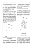
Fuel Rail and Pressure Regulator Valve - Testing
The single fuel rail is used to link the four port injectors to provide a balanced fuel supply at common
pressure, and also to retain the port injectors in the inlet manifold. The left hand end of the fuel rail receives
fuel from the in line filter, and the right hand end houses the pressure regulator valve, from which fuel returns
to the tank. The fuel pressure regulator is a diaphragm operated relief valve with fuel pump pressure acting on
one side of the diaphragm, and regulator spring pressure and intake plenum pressure on the other. The
Page 20
Lotus Service Notes
Section EMN
function of the regulator is to maintain a constant pressure differential across the injectors at all times. i.e. a
constant difference between fuel pressure supplied to the injector, and inlet manifold pressure at the port
injector nozzle. By using an intake plenum pressure signal to supplement regulator spring pressure in the
valve, the valve is able to regulate fuel supply pressure in accordance with engine load. The non-adjustable
pressure regulator is factory set to approximately 3.0 bar, and is serviced as a complete assembly.
To check the fuel pressure:
i)
Relieve fuel pressure as detailed above.
ii)
Connect fuel pressure test gauge T000T1386 into the supply line between the fuel filter and fuel rail using
adaptor T000T1387
Test gauge T000T1386
Adaptor T000T1387
Fuel filter
Fuel feed hose
iii)
iv)
v)
vi)
vii)
em209
Disconnect the vacuum hose between the pressure regulator and the intake plenum.
With the engine idling, the pressure gauge should read 2.9 - 3.1 bar.
If below specification, progressively restrict the fuel return line between regulator valve and tank.
If the specification can then be achieved, the regulator valve is faulty;
If this makes little or no difference, the fuel pump may be restricted or faulty.
If above specification, the regulator valve may be faulty.
With the engine still idling, re-connect the vacuum hose to the regulator valve. The pressure should drop
to approximately 2.2 bar.
If the pressure does not drop, check the hose for kinking or blockage, or replace the regulator valve.
Switch off the ignition and observe the pressure drop after one minute. Pressure should not drop by more
than 0.7 bar.
Too great a pressure drop may be caused by (a) faulty regulator valve; (b) faulty non-return valve in
the fuel pump; (c) leaking injector
If clamping off the return hose reduces the pressure drop, a faulty regulator valve is indicated.
If clamping off the supply hose reduces the pressure drop, a faulty fuel pump is indicated.
If clamping off both hoses does not reduce the pressure drop, a leaking injector is indicated.
To check that the pump has sufficient reserves of delivery for full demand conditions, progressively
clamp off the return hose with the pump running. The pressure should increase by approximately 2 bar.
CAUTION: Only clamp the return hose momentarily and observe the gauge to ensure pressure
does not exceed gauge capacity.
Page 21
Lotus Service Notes
Section EMN
Push Fit Connectors
The fuel rail feed and return hoses are equipped with push fit connectors to allow easy powertrain removal. The feed line connector is colour coded orange, and the return line connector green. Note that the feed
line should not be opened without first carrying out the fuel pressure relief procedure detailed above. With the
system depressurised, cut the safety tie wrap from the connector collar, and use an absorbent cloth to collect
fuel draining from the pipe before pressing the collar into the connector, and separating the joint.
Clean the pipe spigot and lubricate with a light spray of WD40 or similar before remaking the joint,
pressing firmly together until full engagement is indicated be an audible 'click'. Check security by pulling and
twisting the joint. To guard against any possibility of accidental release, fit a small tie wrap (A075W6038Z)
around the release collar as shown.
Fuel feed hose
push fit connector
(orange)
Fuel return hose
push fit connector
(green)
Convolute
sleeving
sb29
Tie wrap fitted around
release collar
sb30
Fuel Injectors
The four fuel injectors are fitted between the pressurised fuel rail and the inlet manifold. Each injector
comprises a solenoid operated needle valve and a specially designed nozzle to ensure good fuel atomisation.
The ECM energises the injectors under engine run conditions, and provides an earth signal for the period the
injectors are required to be open (referred to as 'pulse width'), spraying fuel onto the back of the inlet valves.
Standard engines use group injection, where the fuel injectors are activated in pairs, 1 with 4 and 2 with 3,
whereas VVC engines use fully sequential injection, with each injector activated individually.
During cranking, when the engine speed is below approx. 400 rpm, the ECM increases the pulse width
(dependent on coolant temperature) to aid starting, and on VVC engines, operates the injectors in group mode.
To prevent flooding, the ECM periodically inhibits the operation of the injectors during extended cranking.
Page 22
Lotus Service Notes
Section EMN
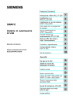
Fuel Rail and Pressure Regulator Valve - Replacement
Do not attempt to remove the pressure regulator valve from the fuel rail; The valve is supplied only as an
assembly with the rail. The fuel rail is removed from the engine complete with the four fuel injectors.
1.
De-pressurise the fuel system, and disconnect the battery.
2.
Remove the breather hose between intake plenum and cam cover, and the breather hose between the
throttle body and cam cover.
3.
Disconnect the vacuum hose between regulator valve and plenum.
4.
Release the fuel return hose from the right hand end of the fuel rail and plug the connections.
5.
Remove the two screws securing the fuel inlet pipe to the left hand end of the rail and withdraw. Discard
the 'O' ring, and plug the connections.
6.
Unplug the injector harness connector, and release from its retaining bracket.
7.
Remove the two bolts securing the fuel rail to the inlet manifold, and carefully withdraw the rail complete
with the four injectors and pressure regulator valve. Take great care not to damage the injector tips
during the removal process. Cap the injectors and plug the manifold ports to prevent dirt ingress.
Pressure sensing
hose
Fuel rail
Fuel rail fixing screw
Fuel pressure
regulator valve
Fuel inlet
pipe
Injector
retaining
clip
Fuel return
pipe
Fuel injector
Inlet manifold
em210
Page 23
Lotus Service Notes
Section EMN
8.
To remove an injector from the rail, unplug the harness connector, remove the clip, and withdraw the
injector from the rail. Discard the two 'O' rings.
9.
Before re-fitting the injectors and rail, clean the injector recesses in the rail and inlet manifold, and fit
each injector with 2 new 'O' rings lubricated with silicone grease. Fit the injectors into the rail, and retain
with the spring clip.
10.
Carefully insert each of the injectors into its inlet manifold bore, and retain the rail with the two fixing bolts,
tightened to 9 Nm.
11.
Continue re-assembly in the reverse order to disassembly, tightening the inlet pipe to rail screws to 4 Nm.
EMN.17 - IGNITION SYSTEM
Standard Engines
The ignition system comprises a single ignition coil mounted on the RH side of the cylinder block, a
distributor driven from the rear end of the inlet camshaft, and low tension control circuitry within the ECM. The
ECM controls ignition timing based on inputs from the following sensors:
Crankshaft position sensor; supplies engine speed and crankshaft position information.
Manifold absolute pressure sensor; supplies engine load information.
Engine coolant temperature sensor; allows timing variations for optimum cold driveability and idle.
Idle Speed Control
The main control over engine idle speed is attained by the use of the idle air control valve. However, for
rapid response, and to inhibit stalling when additional loads are placed on, or removed from the engine, the
ECM varies the ignition timing to achieve idle stabilisation. An observation of idle ignition timing will see a
constantly changing reading.
Ignition Coil
The ignition coil has a low primary winding resistance (0.63 to 0.77 ohms at 20°C) in order to allow full
high tension output to be reached faster than normal, and make coil operation more consistent throughout the
engine speed range.
em203
Ignition coil
Page 24
Lotus Service Notes
Section EMN
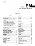
Distributor
A rotor arm is mounted on a 'D' shaped extension to the rear end of the inlet camshaft, and is retained by
a patchlock screw. Always replace the screw, or retreat with Loctite 242. The rotor arm incorporates a suppressor and has a resistance value of 1.25 kohms. The distributor cap is retained by two screws, and is protected from oil contamination from camshaft oil seal leakage by a deflector plate.
Note that there is no requirement, or provision made for, positional adjustment of the distributor.
Inlet camshaft
tail
Rotor
arm
Distributor
cap
em207
Oil deflector
plate
Rotor arm
fixing screw
Distributor cap
fixing screw
VVC Engines
These engines use a Distributorless Ignition System (DIS) employing a pair of double ended coils mounted
on the RH side of the cylinder block. Each coil supplies two spark plugs simultaneously, one to a cylinder on its
compression stroke, and one on its exhaust stroke, the latter being 'wasted' such that the system is sometimes
described as 'wasted spark'. Coil one supplies spark plugs 1 & 4, and coil two supplies plugs 2 & 3.
Each double ended coil contains a primary winding, connected in series with the supply and the ECM, and
an isolated secondary winding, connected in series with two spark plugs. It is important to note that there is no
connection between the primary and secondary windings. The coils are triggered by the ECM which switches
off the primary voltage and induces a high tension current to produce a spark in the spark plug connected to
each end of the secondary winding. The direction in which the secondary winding is wound determines that
plugs 1 & 2 receive positive sparks, and plugs 3 & 4 negative sparks.
It is important to note that if it is necessary to run or crank an engine with one or more plug leads
disconnected, either the coil low tension must be disconnected, or provision for the spark energy to be dissipated must be made (e.g. fitting a loose, grounded spark plug to the lead); otherwise the electrical stess
produced will cause deterioration of the H.T. coil and/or ECM.
Each coil has a primary winding resistance of 0.71 - 0.81 ohms at 20°C and a secondary winding resistance of approx. 10.5 kilohms.
Note that the coils can tolerate a certain amount of water spray, but contamination with anti-freeze solution can result in penetration of the insulation, with consequent danger of current leakage and misfire. Any coil
suspected of being contaminated should be renewed.
Page 25