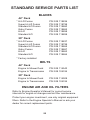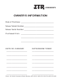
1
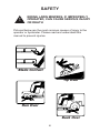
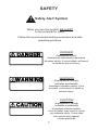
™
RAM SERIES
™
BLACK BEAR
®
ZTR
ZTR®
Safety Instructions
and
Operator’s Manual
RAM 44, BS/968999551
RAM 50, BS/968999552
RAM MAG 44, HON/968999559
RAM MAG 44, KOH/968999560
RAM MAG 50, KAW /968999561
RAM 50 MAG, HON/968999562
RAM 50 MAG KOH/968999563
2
IMPORTANT - READ CAREFULLY
The Dixon® ZTR® mower is both easy and fun to operate.
However, any power mower must be operated properly to be
safe. It is not a toy or a recreational vehicle. Before you start
to use the mower, read this Operator’s Manual carefully. It
contains valuable information that is necessary for the safe
operation of the machine. Observe all safety rules and
become completely familiar with the controls.
The information contained in this manual applies to all Dixon
Ram Series™ ZTR® mowers.
See your authorized Dixon dealer for warranty service, parts
and repairs or to answer any questions you may have about
your new Dixon ZTR.
3
4
TABLE OF CONTENTS
GENERAL OPERATION .................................................................. 8-9
SLOPE OPERATION .................................................... 10-11
FIRE HAZARDS ............................................................ 12-13
CHILDREN, BYSTANDERS AND PETS ............................ 14
SERVICE ............................................................................ 15
SPECIFICATIONS ....................................................................... 12-23
RAM SERIES™ 50 Model 968999552 ............................................. 18
CONTROLS
CONTROL LEVERS ........................................................... 25
PARK BRAKE .................................................................... 26
BLADE DRIVE .................................................................... 27
CHOKE AND THROTTLE CONTROL LEVER ................... 27
MOWER DECK CUT HEIGHT LIFT LEVER ...................... 28
OPERATIONS ............................................................................. 29-39
BEFORE OPERATING MOWER ....................................... 29
STARTING INSTRUCTIONS ............................................. 30
TESTING SAFETY INTERLOCK SYSTEMS ................ 31-32
MULCHING ATTACHMENT ............................................... 33
CATCHER ATTACHMENT ............................................ 35-36
SIDE DISCHARGE ............................................................. 37
GRASS HEIGHT ................................................................ 38
TOWING ............................................................................. 39
CARE AND MAINTENANCE ....................................................... 39-47
UNLOCK TRANSMISSION ................................................ 39
CUTTER BLADES .............................................................. 41
BELTS ................................................................................ 42
BATTERY ........................................................................... 42
LUBRICATION ................................................................... 44
TRACKING ADJUSTMENT ................................................ 45
DECK LEVELING ............................................................... 46
CLEANING ......................................................................... 47
PARTS/SERVICE ............................................................... 47
TROUBLESHOOTING ................................................................. 48-49
STANDARD SERVICE PARTS LIST ................................................ 50
RAM SERIES™
Part Number 539 114246IR
5
SAFETY
!
RIDING LAWN MOWERS, IF IMPROPERLY
OPERATED, CAN CAUSE SERIOUS INJURY
OR DEATH
Pictured below are the most common causes of injury to the
operator or bystander. Please read and understand this
manual to prevent injuries.
Blade Contact
Tip Over
Run Over
Back Over
6
SAFETY
!
Safety Alert Symbol
When you see this symbol, BE ALERT
to the potential for injury.
Follow the recommended safety precautions and safe
operating practices.
DANGER
(highlighted in red)
indicates an imminently hazardous
situation which, if not avoided, will result
in death or serious injury.
WARNING
(highlighted in orange)
indicates a potentially
hazardous situation which, if not
avoided, could result in death or
serious injury.
CAUTION
(highlighted in yellow)
indicates a potentially
hazardous situation which,
if not avoided, may result in minor
or moderate injury. It may also
be used to alert against
unsafe practices.
7
WARNING
!
WARNING
Failure to observe the following instructions
could result in serious injury or death.
GENERAL OPERATION
Read, understand, and follow all instructions in this manual
and on the mower before starting.
Only allow responsible adults, who are familiar with the
instructions, to operate the mower.
Clear the area of objects such as rocks, toys, wire, etc., that
could be picked up and thrown by the blade.
Be sure the area is clear of bystanders before mowing. Stop
mower if anyone enters the area.
Never direct discharged material toward anyone. Avoid
discharging against a wall or obstruction. Material may
ricochet back toward the operator. Stop the blade(s) when
crossing gravel surfaces.
Do not operate the mower without either the entire grass
catcher or the deflector in place. This will decrease the
possibility of injury from objects being thrown by the mower
blades.
Never carry passengers.
Do not mow in reverse unless absolutely necessary. Always
look down and behind before and while backing.
Never leave a running mower unattended. Always turn off
blades, set park brake, stop engine and remove key before
dismounting.
The engine exhaust from this product contains chemicals
known to the State of California to cause cancer, birth defects or other reproductive harm.
8
WARNING
!
WARNING
Failure to observe the following instructions
could result in serious injury or death.
GENERAL OPERATION (continued)
Turn off blades when not mowing. Injury could occur from
contact with moving parts.
Under no circumstances should you place hands or feet
under the mower deck or in the chute while blades or
impeller are still running.
To avoid personal injury from accidental clutch engagement,
stop engine before removing grass catcher or unclogging
chute.
Mow only in daylight or good artificial light.
Do not operate the mower while under the influence of
alcohol or drugs.
Slow down before turning to reduce the risk of tip-over.
Watch for traffic when operating near or crossing roadways.
Use extra care when loading or unloading the mower into a
trailer or truck. Push, do not ride the mower when loading
and unloading.
Protect your eyes. Always wear safety goggles or safety
glasses with side shields when operating mower.
Data indicates that operators, age 60 years and above, are
involved in a large percentage of riding mower-related
injuries. These operators should evaluate their ability to
operate the riding mower safely enough to protect
themselves and others from serious injury.
To protect against possible tip-over, follow the
manufacturer’s recommendation for wheel weights and
counterweights.
Maintain or replace safety and instruction labels as needed.
9
WARNING
!
WARNING Failure to observe the following instructions
could result in serious injury or death.
SLOPE OPERATION
Slopes are a major factor related to loss-of-control and
tip-over accidents, which can result in severe injury or
death.
All slopes require extra caution. If you feel unsure on
any slope, do not mow it!
DO
Mow across the slope with your Dixon ZTR — never up or
down. This will decrease the risk of tip-over.
Remove obstacles such as rocks, tree limbs, wires and other
foreign objects that can be thrown by mower blades.
Watch for holes, ruts, roots and bumps, and uneven terrain
that could overturn the mower. Tall grass can hide such
obstacles.
Use slow speed. Tires may lose traction on slopes even
though the brakes are functioning properly.
Avoid starting or stopping on a slope. If tires lose traction,
disengage the blades and proceed slowly down the slope.
Keep all movement on the slopes slow and gradual. Do not
make sudden changes in speed or direction.
Use extreme caution when operating the mower with
attachments to prevent tip-over or roll-over.
If front wheels lift off the ground, pull levers back to stabilize
the mower. Discontinue mowing the slope!
10
WARNING
!
WARNING
Failure to observe the following instructions
could result in serious injury or death.
SLOPE OPERATION (continued)
DO NOT
Do not turn on slopes unless necessary, and then, turn
slowly and gradually downhill, if possible. Rapid uphill turns
may cause tip-over.
Do not mow near drop-offs, ditches, or embankments.
Unstable ground may cause loss of control.
Do not mow on wet grass. Reduced traction could cause
sliding.
Do not try to stabilize the mower by putting your foot on the
ground.
Do not use grass catcher or other attachments on steep
slopes. The added weight may change the stability of the
mower, creating the potential for tip-over.
11
WARNING
!
WARNING
Failure to observe the following instructions
could result in serious injury or death.
FIRE HAZARDS
Use extra care when handling gasoline and other fuels. They
are flammable and vapors are explosive.
Store all fuel in approved containers specifically designed for
that purpose.
Allow engine to cool before refueling. Never remove fuel cap
or add fuel with engine running.
Do not smoke while refueling or operating the mower.
To reduce fire hazard, keep mower free of grass, leaves and
other debris buildup.
If gasoline is spilled, do not attempt to start the engine. Move
mower away from the area of the spill. Do not create any
source of ignition until gas vapors have dissipated. Wipe up
spilled fuel and dispose of waste properly.
If fuel is spilled on clothing, change clothing immediately.
Before storing, allow mower to cool. Clean fuel and oil
spillage.
Never store the mower or fuel container inside a building
where there is an open flame.
12
WARNING
!
WARNING
Failure to observe the following instructions
could result in serious injury or death.
FIRE HAZARDS (continued)
To prevent fire or explosion, keep sparks and open flames
away from battery.
Keep electrical connections clean and tight. Inspect them
often. Loose connections and corrosion increase fire risk.
Before disconnecting the negative ground cable, make sure
all switches are off. This decreases the chance of sparking
and fire.
Use care when backing to avoid pushing the grass bags into
the frame or “hot” exhaust muffler of the engine. Fire could
result.
To prevent fire and explosion caused by static electricity:
Never fill containers inside a vehicle or on a truck or
trailer bed with a plastic liner. Always place containers
on the ground away from your vehicle before filling.
When practical, remove fuel powered equipment from
the truck or trailer and refuel it on the ground. If this is
not possible, refuel such equipment on a trailer with a
portable container, rather than from a fuel dispenser
nozzle.
If a fuel dispenser nozzle must be used, keep the
nozzle in contact with the rim of the fuel tank or
container opening at all times until fueling is complete.
Do not use a nozzle lock-open device.
13
WARNING
!
WARNING
Failure to observe the following instructions
could result in serious injury or death.
CHILDREN, BYSTANDERS AND PETS
Tragic accidents can occur if the operator is not alert to
the presence of children, bystanders and pets.
Children are attracted to lawn mowers
and the mowing activity.
NEVER assume children, bystanders and pets
will stay where they were last seen.
Be alert to avoid accidents.
Keep bystanders and pets out of the mowing area and keep
children under the watchful care of another responsible adult.
Be alert and turn mower off if bystanders, children or pets
enter the area.
Before and during backing look BEHIND and DOWN for
small children.
Never carry children as passengers. They may fall off and be
seriously injured or interfere with safe mower operation.
Never allow children to operate the mower.
Use extra care when approaching blind corners, shrubs,
trees, or other objects that may obscure vision.
14
WARNING
!
WARNING
Failure to observe the following instructions
could result in serious injury or death.
SERVICE
Never run a mower inside a closed area or without proper
ventilation.
Keep nuts and bolts tight, especially blade attachment bolts,
and keep equipment in good condition.
Never tamper with safety devices. Check their proper
operation regularly.
Stop and inspect the equipment if you strike an object.
Repair, if necessary, before restarting.
Never make adjustments or repairs with the engine running
unless otherwise specified.
Grass catcher components are subject to wear, damage and
deterioration that could expose moving parts or allow objects
to be thrown. Frequently check components. Replace with
original equipment parts when necessary.
When servicing blades, wrap blades or wear gloves, and use
extra caution.
Batteries contain sulfuric acid. To prevent burns, avoid
contact with skin, eyes and clothing.
15
DIXON® ZTR® COMMERCIAL / RESIDENTIAL WARRANTY POLICY
RAM 44, RAM 50, RAM 44 MAG™ & RAM 50 MAG™
DIXON® WARRANTS ITS ZTR® MOWERS AGAINST DEFECTS IN MATERIAL AND WORKMANSHIP FOR
THE PERIODS SET FORTH BELOW. THE SOLE REMEDY UNDER THIS WARRANTY
IS REPLACEMENT OR REPAIR OF PARTS INCLUDING LABOR COSTS.
THIS WARRANTY IS SUBJECT TO THE FOLLOWING CONDITIONS AND LIMITATIONS:
1. COMMERCIAL WARRANTY (use other than, or in addition to, mowing at owner’s primary place of
residence):
a. One Year - 100% parts and labor subject to the conditions and limitations described herein for a
period of one year from date of purchase by the original owner.
b. Attachments marketed through or approved by Dixon are warranted for one year parts and labor in
commercial use applications.
c. The RAM 44, RAM 50, RAM 44 MAG™ and RAM 50 MAG™ are not subject to hour meter
restrictions.
d. Warranty applies to new mowers.
2. RESIDENTIAL WARRANTY (used only at owner’s primary place of residence):
a. Two years - 100% parts and labor subject to the conditions and limitations described herein for a
period of two years from date of purchase by the original owner.
b. Third year - limited to 100% parts cost as shown in the current Dixon® Parts Price List and subject to
the conditions and limitations as described herein.
c. Attachments marketed through or approved by Dixon are warranted for two years parts and labor in
residential use applications.
d. Warranty applies to new mowers.
3. Lifetime warranty on all frames and leading edge of all fabricated (welded) decks.
4. All Dixon® warranty must be accomplished by authorized Dixon® dealers and in accordance with Dixon®
warranty policy and allowances.
All warranty claims must be submitted to Dixon for approval.
5. Warranty labor reimbursement to dealers based on published Dixon® flat rate schedule.
6. Warranty does not apply to damage in transit or incidents of misuse, negligence, accidents, or alteration.
The use of parts or components other than those supplied by Dixon VOIDS ALL WARRANTY.
7. Battery warranty is limited to 1 year from mower manufacture date.
8. The following items are not covered by this warranty policy:
a. Routine maintenance or adjustments to include any oils, filters or other fluids used.
b. Belts, blades, tires and cosmetic appearance (paint, seat fade, etc.)
c. Pick up and delivery charges for transportation of mower to and from an authorized Dixon® dealer’s
place of business.
d. Engines. These are covered under a separate warranty by each individual engine manufacturer.
Consult engine manual for warranty details.
e. Any costs or expense of providing substitute equipment while repair work is being performed on a
warranted mower.
9. THERE IS NO OTHER EXPRESS WARRANTY. TO THE EXTENT PERMITTED BY LAW, ALL IMPLIED
WARRANTIES, INCLUDING THOSE OF MERCHANTABILITY AND FITNESS FOR A PARTICULAR
PURPOSE ARE EXCLUDED, OTHERWISE, ALL SUCH IMPLIED WARRANTIES ARE LIMITED TO THE
SAME DURATION AND REMEDIES AS THE EXPRESS WARRANTY. ALL LIABILITIES FOR
CONSEQUENTIAL DAMAGES UNDER ANY EXPRESS OR IMPLIED WARRANTY ARE EXCLUDED.
16
SPECIFICATIONS
RAM SERIES™ 44 Model 968999551
Chassis:
1½" square tube side frame
Mower Deck:
Made of 11 gauge fabricated welded construction
with external reinforcement ribs. Three blades
combine for a 42" (107cm) cut width. Cut height
approximately 1½" (38mm) to 4½" (114 mm).
Blade Drive:
Electric clutch
Drive System:
Each rear wheel is independently driven by a
Hydro Gear hydrostatic drive ZT2800 7" cooling
fan.
Engine:
26 HP Briggs & Stratton, twin cylinder, overhead
valve, air cooled, gasoline, full pressure lube with
oil filter, vertical shaft, aluminum head & block with
cast- iron cylinder liners.
Starting
System:
Electric-key switch operation with safety interlocks
on park brake and blade drive clutch.
Tires:
Front
11 x 4.5 x 5 smooth tread
15 PSI
(103 kPa)
Rear
18 X 9.5 X 8 Turf pneumatic
15 PSI
(103 kPa)
Capacities:
Fuel
Engine Oil
4.9 gallon (19 liters) approximately
2 qts. (1.8 liters) SAE 10W30
with filter
Dimensions:
Width
Height
Length
Weight
44" (112 cm)
40" (102 cm)
69½" (177 cm)
625 lbs. (283 kg)
Additional information may be provided elsewhere in this manual.
SPECIFICATIONS SUBJECT TO CHANGE WITHOUT NOTICE
17
SPECIFICATIONS
RAM SERIES™ 50 Model 968999552
Chassis:
1½" square tube side frame
Mower Deck:
Made of 11 gauge fabricated welded construction
with external reinforcement ribs. Three blades
combine for a 48" (122cm) cut width. Cut height
approximately 1½" (38mm) to 4" (114 mm).
Blade Drive:
Electric clutch
Drive System:
Each rear wheel is independently driven by a
Hydro Gear ZT2800 hydrostatic drive 7" cooling
fan.
Engine:
26 HP Briggs and Stratton engine, overhead
valve, air cooled, gasoline, full pressure lube with
oil filter, vertical shaft, aluminum head and block
with cast-iron cylinder liners.
Starting
System:
Electric-key switch operation with safety interlocks
on park brake and blade drive clutch.
Tires:
Front
11 x 4.5 x 5 smooth tread
15 PSI
(103 kPa)
Rear
18 X 9.5 X 8 Turf pneumatic
15 PSI
(103 kPa)
Capacities:
Fuel
Engine Oil
4.9 gallon (19 liters) approximately
2 qts. (1.8 liters) SAE 10W30
with filter
Dimensions:
Width
Height
Length
Weight
50" (112 cm)
40" (102 cm)
72" (183 cm)
605 lbs. (274 kg)
Additional information may be provided elsewhere in this manual.
SPECIFICATIONS SUBJECT TO CHANGE WITHOUT NOTICE
18
SPECIFICATIONS
RAM MAG SERIES™ 44 Model 968999559
Chassis:
1½" square tube side frame
Mower Deck:
Made of 11 gauge fabricated welded construction
with external reinforcement ribs. Three blades
combine for a 42" (107cm) cut width. Cut height
approximately 1½" (38mm) to 4" (114 mm).
Blade Drive:
Electric clutch
Drive System:
Each rear wheel is independently driven by a
Hydro Gear ZT2800 hydrostatic drive with integral
charge pump and 7" cooling fan.
Engine:
20 HP Honda engine, overhead valve, air cooled,
gasoline, full pressure lube with oil filter, vertical
shaft, aluminum head and block with cast-iron
cylinder liners.
Starting
System:
Electric-key switch operation with safety interlocks
on park brake and blade drive clutch.
Tires:
Front
11 x 4.5 x 5 smooth tread
15 PSI
(103 kPa)
Rear
18 X 9.5 X 8 Turf pneumatic
15 PSI
(103 kPa)
Capacities:
Fuel
Engine Oil
4.9 gallon (19 liters) approximately
2 qts. (1.8 liters) SAE 10W30
with filter
Dimensions:
Width
Height
Length
Weight
44" (112 cm)
40" (102 cm)
69½" (177 cm)
625 lbs. (283 kg)
Additional information may be provided elsewhere in this manual.
SPECIFICATIONS SUBJECT TO CHANGE WITHOUT NOTICE
19
SPECIFICATIONS
RAM MAG SERIES™ 44 Model 968999560
Chassis:
1½" square tube side frame
Mower Deck:
Made of 11 gauge fabricated welded construction
with external reinforcement ribs. Three blades
combine for a 42" (107cm) cut width. Cut height
approximately 1½" (38mm) to 4" (114 mm).
Blade Drive:
Electric clutch
Drive System:
Each rear wheel is independently driven by a
Hydro Gear ZT2800 hydrostatic drive with integral
charge pump and 7" cooling fan.
Engine:
20 HP Kohler engine, overhead valve, air cooled,
gasoline, full pressure lube with oil filter, vertical
shaft, aluminum head and block with cast-iron
cylinder liners.
Starting
System:
Electric-key switch operation with safety interlocks
on park brake and blade drive clutch.
Tires:
Front
11 x 4.5 x 5 smooth tread
15 PSI
(103 kPa)
Rear
18 X 9.5 X 8 Turf pneumatic
15 PSI
(103 kPa)
Capacities:
Fuel
Engine Oil
4.9 gallon (19 liters) approximately
2 qts. (1.8 liters) SAE 10W30
with filter
Dimensions:
Width
Height
Length
Weight
44" (112 cm)
40" (102 cm)
72" (183 cm)
625 lbs. (283 kg)
Additional information may be provided elsewhere in this manual.
SPECIFICATIONS SUBJECT TO CHANGE WITHOUT NOTICE
20
SPECIFICATIONS
RAM MAG SERIES™ 50 Model 968999561
Chassis:
1½" square tube side frame
Mower Deck:
Made of 11 gauge fabricated welded construction
with external reinforcement ribs. Three blades
combine for a 48" (122cm) cut width. Cut height
approximately 1½" (38mm) to 4" (114 mm).
Blade Drive:
Electric clutch
Drive System:
Each rear wheel is independently driven by a
Hydro Gear ZT2800 hydrostatic drive with integral
charge pump and 7" cooling fan.
Engine:
21 HP Kawasaki, twin cylinder, overhead valve, air
cooled, gasoline, full pressure lube with oil filter,
vertical shaft, aluminum head & block with castiron cylinder liners with heavy duty canister air
cleaner.
Starting
System:
Electric-key switch operation with safety interlocks
on park brake and blade drive clutch.
Tires:
Front
11 x 4.5 x 5 smooth tread
15 PSI
(103 kPa)
Rear
18 X 9.5 X 8 Turf pneumatic
15 PSI
(103 kPa)
Capacities:
Fuel
Engine Oil
4.9 gallon (19 liters) approximately
2 qts. (1.8 liters) SAE 10W30
with filter
Dimensions:
Width
Height
Length
Weight
50" (127 cm)
40" (102 cm)
72" (183 cm)
605 lbs. (274 kg)
Additional information may be provided elsewhere in this manual.
SPECIFICATIONS SUBJECT TO CHANGE WITHOUT NOTICE
21
SPECIFICATIONS
RAM MAG SERIES™ 50 Model 968999562
Chassis:
1½" square tube side frame
Mower Deck:
Made of 11 gauge fabricated welded construction
with external reinforcement ribs. Three blades
combine for a 48" (122cm) cut width. Cut height
approximately 1½" (38mm) to 4" (114 mm).
Blade Drive:
Electric clutch
Drive System:
Each rear wheel is independently driven by a
Hydro Gear ZT2800 hydrostatic drive with integral
charge pump and 7" cooling fan.
Engine:
20 HP Honda, twin cylinder, overhead valve, air
cooled, gasoline, full pressure lube with oil filter,
vertical shaft, aluminum head & block with castiron cylinder liners.
Starting
System:
Electric-key switch operation with safety interlocks
on park brake and blade drive clutch.
Tires:
Front
11 x 4.5 x 5 smooth tread
15 PSI
(103 kPa)
Rear
18 X 9.5 X 8 Turf pneumatic
15 PSI
(103 kPa)
Capacities:
Fuel
Engine Oil
4.9 gallon (19 liters) approximately
2 qts. (1.8 liters) SAE 10W30
with filter
Dimensions:
Width
Height
Length
Weight
50" (112 cm)
40" (102 cm)
72" (183 cm)
605 lbs. (274 kg)
Additional information may be provided elsewhere in this manual.
SPECIFICATIONS SUBJECT TO CHANGE WITHOUT NOTICE
22
SPECIFICATIONS
RAM MAG SERIES™ 50 Model 968999563
Chassis:
1½" square tube side frame
Mower Deck:
Made of 11 gauge fabricated welded construction
with external reinforcement ribs. Three blades
combine for a 48" (122cm) cut width. Cut height
approximately 1½" (38mm) to 4½" (114 mm).
Blade Drive:
Electric clutch
Drive System:
Each rear wheel is independently driven by a
Hydro Gear ZT2800 hydrostatic drive with integral
charge pump and 7" cooling fan.
Engine:
20 HP Kohler, twin cylinder, overhead valve, air
cooled, gasoline, full pressure lube with oil filter,
vertical shaft, aluminum head & block with castiron cylinder liners.
Starting
System:
Electric-key switch operation with safety interlocks
on park brake and blade drive clutch.
Tires:
Front
11 x 4.5 x 5 smooth tread
15 PSI
(103 kPa)
Rear
18 X 9.5 X 8 Turf pneumatic
15 PSI
(103 kPa)
Capacities:
Fuel
Engine Oil
4.9 gallon (19 liters) approximately
2 qts. (1.8 liters) SAE 10W30
with filter
Dimensions:
Width
Height
Length
Weight
50" (127 cm)
40" (102 cm)
74½" (189 cm)
605 lbs. (274 kg)
Additional information may be provided elsewhere in this manual.
SPECIFICATIONS SUBJECT TO CHANGE WITHOUT NOTICE
23
SEAT ADJUSTMENT INSTRUCTIONS
1.
Grasp seat slide adjuster and move it into adjustment
position.
2.
Slide seat forward or backward.
3.
Release seat slide adjuster.
Seat Slide
Adjuster
—Fig. 1—
24
CONTROLS
CONTROL LEVERS
For access to the seat, move control levers to neutral
position and swing them outward.
NEUTRAL
SLOW
FORWARD
FAST
FORWARD
90o
RIGHT
—Fig. 2—
SLOW
REVERSE
TURN
Left Turn Opposite
TO GO FORWARD
• From neutral position, gently push control levers
forward.
• To increase speed, move levers further forward.
TO GO BACKWARDS
• From neutral position, gently pull control levers
toward you.
TURNING
• Turning is controlled by moving one control lever slightly
forward or rearward of the other.
• To turn left, move left lever rearward of the right lever.
• To turn right, move right lever rearward of the left lever.
• To turn on mower’s own axis (zero turning radius), stop
and move one lever to reverse position and the other to
forward position.
BRAKING
• To brake mower, move both levers in direction opposite
of travel.
NOTE: The pressure required to operate the mower is very light.
25
CONTROLS
PARK BRAKE
The park brake is designed to hold the mower
from moving and is not intended for use in
stopping the mower while it is in motion. The
engine will stop if the park brake is engaged while
the control levers are in the drive position.
!
CAUTION
Engage park brake before
starting engine.
TO SET PARK BRAKE
The hand-operated park brake is located on the
left hand side.
•To engage brake, pull lever up (to the rear).
•To release brake, move lever forward (down).
NOTE: Always set park brake before dismounting.
Release park brake before moving mower.
26
—Fig. 3—
CONTROLS
BLADE DRIVE
•
•
•
Located on the control panel, on operator’s right.
To engage the mower blade, pull up on the switch.
To disengage mower blade, push down.
CHOKE AND THROTTLE CONTROL LEVER
•
•
27
ON
—Fig. 4—
STOP
BLADES
•
•
Located on control panel to
operator’s right.
Throttle control for engine
speed.
Choke for engine starting.
Throttle control should be set to
MAXIMUM or wide open setting
to insure adequate cooling of
the engine and to maintain
mower deck blade speed while
mowing.
OPERATION INSTRUCTIONS
MOWER DECK CUT HEIGHT LIFT LEVER
•
•
•
•
•
Use right foot to operate deck foot pedal at right front foot
area.
To raise mower deck, push forward with right foot on top
portion of foot pedal. When desired deck height is
reached, push with right foot on lower portion of foot pedal
until the bottom of the foot pedal engages in deck
positioning notch.
To lower deck, push forward with right foot on top portion
of foot pedal until bottom edge of foot pedal disengages
deck positioning notch. Lower deck to desired height and
push bottom portion of foot pedal until bottom edge
engages notch.
Never attempt to operate deck lift mechanism in any
manner, other than foot method described above.
Always use highest position for transport.
28
OPERATION INSTRUCTIONS
The safe and successful operation of the RAM will depend
on the operator having the correct knowledge of all controls
used on the mower and making good judgements about the
terrain to be mowed.
NEVER allow anyone without complete knowledge of all
controls and their functions to operate the mower.
During initial operation, “learning to drive”, set throttle at slow
speed.
Sound judgement by the operator will prevent accidents.
BEFORE OPERATING MOWER
1. Read engine manufacturer’s operating and maintenance
instructions.
2. Read and observe all safety instructions on your mower
and in the manual.
3. Check engine oil.
4. Check fuel cap to be sure it is in place.
5. Be sure park brake is on.
6. Be sure mower blade drive is off.
7. Know how to stop engine. (Turn key to OFF position).
29
OPERATION INSTRUCTIONS
!
CAUTION
Failure to observe the following instructions
could result in personal injury.
STARTING INSTRUCTIONS
1. Park brake must be on, control levers in outward position
and blade drive disengaged.
2. Position throttle to desired speed setting. If engine is cold,
position choke lever in the ON position.
NOTE: Engine may require partial choke setting to start even if
the engine has been operated for a period of time.
3. Insert ignition key and turn to START position. When
engine starts, release ignition key. Key will return to RUN
position.
4. Return choke to OFF position, if applicable.
5. Move throttle to maximum speed position.
6. Release park brake.
7. Swing levers inward.
8. Operate mower per CONTROL instructions on Page 25.
!
CAUTION
Note:
Do not operate the engine in an enclosed
area due to the harmful exhaust gas
produced.
When mowing with blades engaged, set throttle control
to the MAXIMUM or wide open setting to insure adequate
cooling of the engine and to maintain mower deck blade
speed.
30
OPERATION INSTRUCTIONS
TESTING OF SAFETY INTERLOCK SYSTEMS
!
WARNING
Failure to observe the following instructions
could result in serious injury or death.
The following tests should be performed at the start of
each mowing day.
PARK BRAKE SWITCH TEST
1.
2.
3.
4.
Swing control levers to outward position.
Disengage blade drive.
Put park brake in OFF position.
Turn ignition switch to START.
Engine should not turn over or attempt to start.
CONTROL LEVER SWITCH TEST
1.
2.
3.
4.
Disengage blade drive.
Put park brake in ON position.
Swing control levers inward.
Turn ignition switch to START.
Engine should not turn over or attempt to start.
NOTE: If any safety check fails, do not operate the mower until
the system has been checked and repaired by an
authorized Dixon dealer.
31
OPERATION INSTRUCTIONS
TESTING OF SAFETY INTERLOCK SYSTEMS
!
WARNING
Failure to observe the following instructions
could result in serious injury or death.
The following tests should be performed at the start of
each mowing day.
BLADE DRIVE SWITCH TEST
1.
2.
3.
4.
Put park brake in ON position.
Swing control levers to outward position.
Engage blade drive.
Turn ignition switch to START.
Engine should not turn over or attempt to start.
SEAT SWITCH TEST
1. In a SAFE AREA away from bystanders, start the engine.
2. Leave control levers in outward position and put park
brake ON position.
3. Engage blade drive.
4. Raise slightly off seat. Engine should stop!
NOTE: If any safety check fails, do not operate the mower until
the system has been checked and repaired by an
authorized Dixon dealer.
32
OPERATION INSTRUCTIONS
MOWING WITH A MULCHING ATTACHMENT
Mulching or recycling the grass clippings requires a totally
different mowing approach than would be normal when side
discharging or bagging the grass. There may be instances or
conditions where it is not possible to hide all the recycled or
mulched clippings.
In order to achieve the best results, please read and follow
the mulching tips listed below:
1. Read and follow the installation instructions that are
included with your mulcher.
2. Set the engine speed control to the wide open or full
setting.
3. Place the mower deck cut height selector in either the top
or second notch. Never cut more than ¾" (19 mm) to 1"
(25mm) off the grass at any one time. Attempting to cut
more grass will result in the deck plugging and cause the
engine to stall.
4. It may be necessary to cut the lawn twice to achieve
acceptable mulching performance especially on first
cuttings or if the lawn is heavily fertilized.
5. Do not attempt to cut grass when it is wet. Mulching
performance will be very poor in wet grass conditions.
6. Maintain sharp blades throughout the cutting season. This
is very important. Optimal mulching performance cannot
be obtained with a dull or nicked blade.
33
OPERATION INSTRUCTIONS
MOWING WITH A MULCHING ATTACHMENT
(continued)
7. Keep the underside of the mower deck clean. Remove
all grass and dirt buildup from the underside of the pan,
the baffles and deflectors after each use. Never, under
any circumstances, should you place hands or feet
under the mower deck or in the chute while blades or
impeller are still turning.
8. Alternate mower direction. This will evenly disperse the
mulched grass clippings over the lawn for even
fertilization.
If the mulching quality of the mower does not seem
to be satisfactory, try one or more of the following
tips:
•
•
•
•
•
•
Raise the height-of-cut setting on your mower.
Cut grass more frequently.
Operate the mower at a slower ground speed.
Overlap cutting swaths instead of cutting a full swath with
each pass.
Mow across the marginal areas a second time.
CUT HIGH - MOW OFTEN!
34
OPERATION INSTRUCTIONS
MOWING WITH A
GRASS CATCHER ATTACHMENT
In order to achieve optimum performance when mowing with
a grass catching attachment, please read and follow the tips
listed below.
1. Read and follow the installation instructions that are
included with your grass catcher.
2. Set engine speed control to the wide open or full setting.
3. Do not attempt to cut grass when it is wet. Wet grass will
clog both the underside of the deck and the attachment
chutes. Empty bags often to prevent plugging.
4. If the grass is tall, place the mower deck cut height
selector in the top or second notch. “Initially” overlap
cutting swaths instead of a full swath with each pass.
5. Keep the underside of the mower deck clean. Frequent
removal of dried grass and dirt will greatly assist in
bagging of the clippings. Never, under any
circumstances, should you place hands or feet under
the mower deck or in the chute while blades or
impeller are still turning.
6. Operate the mower at a slower ground speed than when
mowing without a grass catching attachment.
35
OPERATION INSTRUCTIONS
MOWING WITH A
GRASS CATCHER ATTACHMENT (continued)
7. Maintain sharp blades throughout the cutting season.
Some grass catching attachments require a “high-lift”
blade. See your dealer for advice on the type of blade(s)
needed for your mower.
8. Some mowing applications or use of grass catchers may
require that an additional weight kit be fitted to the mower
to counter the weight of grass in the bags. Please consult
with your dealer for more information regarding
installation and adding weight to the box.
!
WARNING
Failure to observe the following instructions
could result in serious injury or death.
• Watch for low hanging branches or other obstacles that
might hit the catcher top while turning or backing the
mower.
• Use care when backing to avoid pushing the grass bags
into the frame or “hot” exhaust muffler of the engine. Fire
could result.
• Disengage blade and stop engine prior to clearing grass
from either the discharge chute or grass catcher
components.
• Do not operate the mower with the grass catching
attachment partially removed. Operator or bystanders
could be injured by thrown objects.
• Keep all attachment bolts tight.
• Important: Do not leave clippings in the bags while the
mower is stored. Damp grass clippings are a fire hazard if
left in the bag.
36
OPERATION INSTRUCTIONS
SIDE DISCHARGE OF THE CLIPPINGS
In order to achieve optimum performance when side
discharging the grass clippings, please read and follow the
tips listed below. Additional information can be found in the
Troubleshooting guide on Page 48-49.
!
CAUTION
To avoid personal injury, be sure that the
deflector is properly installed on the
discharge chute.
1. Set engine speed control to the wide open or full setting.
2. Do not attempt to cut grass when it is wet. Wet grass will
clog the underside of the deck and discharge area.
3. If the grass is tall, place the mower deck cut height lever
in the top or second notch. “Initially” overlap cutting
swaths instead of a full swath with each pass. Some
applications may require a second cutting.
4. Keep the underside of the mower deck clean. Frequent
removal of dried grass and dirt will allow the clippings to
discharge correctly. Never, under any circumstances,
place your hands or feet under the mower deck or in
the chute while blades or impeller are still turning.
5. Maintain sharp blade(s) throughout the cutting season.
37
OPERATION INSTRUCTIONS
GRASS HEIGHT AND CUTTING SUGGESTIONS
Do not attempt to cut grass when it is wet.
If the grass is tall, place the mower deck cut height lever in
the top or second notch. “Initially” overlap cutting swaths
instead of a full swath with each pass. Some applications
may require a second cutting.
Keep the underside of the mower deck clean.
Maintain sharp blades throughout the cutting season.
As a rule of thumb, never cut off more than one third of the
total grass blade length. Correct mowing height can reduce
weeds and disease by 50% to 80%.
The following grass cut heights are based on adequate
moisture conditions and normal thatch buildup in a healthy
lawn. Some locations and applications may require slightly
different cut heights. If in doubt, consult your local lawn
professional for assistance.
Grass Types
Bermudagrass
Bluegrass
Buffalograss
Ryegrass
Tall Fescue
Zoysiagrass
Best Cut Heights
1 - 2" (25-51 mm)
2 - 3" (51-76 mm)
1½ -3" (38-76 mm)
2 - 3" (51-76 mm)
3-3½" (76-89 mm)
1 - 3" (25-76 mm)
38
OPERATION INSTRUCTIONS
TOWING TRAILERS AND
OTHER ATTACHMENTS
Towing a trailer or other attachment that is too heavy could
damage the drive or cause the mower to become unstable.
Limit loads to 250 pounds (113 kg) or less with this mower.
To Free Wheel Machine
(Unlock Transmission)
When pushing or pulling the mower, be sure to engage the
hydro release levers. Always turn off engine before engaging
or disengaging the hydro release (free wheel) lever. Never
attempt to move the lever with the engine running.
•
•
•
Raise the deck to the highest cutting position.
Pull the bypass lever out and into the slots so that it is
held in the bypass position.
To reengage to drive, reverse the above procedure.
—Fig. 5—
Hydro Release Lever
with the head outside the
rear deck—bypass position
NOTE: Before pushing or towing tractor, transmission must be
unlocked and park brake released. The tractor should
never be pulled at more than 2 miles per hour (3.2 km/h)
or for distances over ¼ mile (.402 km). Trailer the unit for
distances over ¼ mile.
39
CARE AND MAINTENANCE
!
CAUTION
Failure to observe the following instructions
could result in personal injury.
Before performing any maintenance, turn off engine,
allow to cool and remove key.
Use extreme care when working on machinery.
Do not wear watch or jewelry.
Do not wear loose fitting clothes, and observe all
common safety practices with tools.
MAINTENANCE SCHEDULE
•Check deck belt ............................................... after 20 hours break-in
•Check crankcase oil level ........................................... before each use
•Clean grass & debris from muffler & manifold area .... before each use
•Check air intake screen ................................................. after each use
•Clean grass under deck. ............................................... after each use
•Check tire pressure ...................................................... every 10 hours
•Inspect blades for sharpness ....................................... every 10 hours
•Clean air filter element. ................................................. every 25 hours
•Grease all zerks ........................................................... every 50 hours
•Check all belts .............................................................. every 50 hours
•Change engine crankcase oil & filter ................ (5 hours break-in) and
...................................................................................... every 50 hours
•Change engine oil filter ................................................. every 50 hours
•Replace air filter element ......................... annually or every 100 hours
40
CARE AND MAINTENANCE
!
CAUTION
Stop engine and remove ignition
key for safety. Wear heavy, thick
gloves when holding onto cutter
blade, avoid the sharp edge of
the blade.
CUTTER BLADE MAINTENANCE
Check sharpness of mower blades after every 10 hours of
operation. Observe proper blade position
prior to removal.
1. Safely raise front of mower.
2. Hold or block blade from turning.
3. Loosen blade bolt and remove blade.
4. When replacing blade, tighten
blade bolt securely. Refer to
Fig 6. Tighten blade bolt
to 60 ft. lbs. (81Nm)
—Fig. 6—
Blades should be discarded when worn excessively.
New blade
—Fig. 7—
When notch starts,
discard blade
41
DANGEROUS!
Do not use blade
in this condition!
CARE AND MAINTENANCE
BELTS
Check belts every 100 hours. Replace any belts showing
signs of severe cracking or large nicks. Belts are not
adjustable, replace if they begin to slip from wear.
ENGINE
For complete maintenance and operating information of the
engine, please refer to the maintenance instructions
furnished by the engine manufacturer and included in your
Zero Turn Radius mower information packet.
!
CAUTION
Battery contains sulfuric acid
electrolyte that is poisonous and
corrosive.
BATTERY
This is a maintenance-free battery and the fluid level cannot
be checked. Charge battery if required.
OFF SEASON BATTERY STORAGE
•
•
•
•
•
DO NOT remove battery from mower.
Clean top of battery and terminals with baking soda
and water.
Identify each cable so they can be reconnected to the
correct terminal.
Disconnect cables from terminals. ALWAYS disconnect
ground cable first and reconnect last.
Charge battery.
NOTE: Your Dixon mower comes equipped with a quick
disconnect harness for the optional Dixon Battery
Manager. The Dixon Battery Manager maintains the
proper charge levels during periods of inactivity and may
prevent premature battery failures. Contact your dealer
for more information.
42
CARE AND MAINTENANCE
TIRES
Correct tire pressure is essential for efficient operation of the
mower. Check tire pressure periodically. Inflate tires to the
pressure listed below.
Front tires 11 x 4.50 - 5
15 PSI (103 kPa)
Rear tires
18 x 9.50 - 8
15 PSI (103 kPa)
Lug nuts or lug bolts should be checked regularly for tightness.
LUBRICATION
CHASSIS:
(11) grease zerks
LOCATIONS:
(2) front wheels
(1) mower deck hubs
SERVICE INTERVALS:
Every 50 hours of operation or
once per season
RECOMMENDED
GREASE:
Name brand wheel bearing
or multipurpose grease
(3 pumps each)
—Fig. 8—
43
CARE AND MAINTENANCE
!
CAUTION
HOT oil may cause burns. Allow engine to
cool before draining oil.
CHANGING THE ENGINE OIL
1. The “Dapco” oil drain valve is located on the left side of
the engine crankcase.
2. Place a suitable container under the drain valve hose.
3. To drain, turn hex head valve stem counter-clockwise with
a 10mm wrench or socket. Open to full open
(approximately 7 turns).
4. After engine is drained, tighten hex stem.
5. Change oil filter.
6. Fill with oil (see steps below).
Hex Head
Valve Stem
—Fig. 9—
NOTE: Refer to engine manufacturer’s recommendations for
frequency of oil changes.
OIL FILL
1. Clean any spilled oil from engine and chassis.
2. Refill engine with type, and quantity of oil recommended
by the engine manufacturer in engine literature.
NOTE: Engine oil changes on the Ram Series will require
replacement of the oil filter. These filters may be available
from your local Dixon Dealer.
44
CARE AND MAINTENANCE
TRACKING ADJUSTMENT
If the mower is not tracking straight, check the air pressure in
both rear tires. Recommended air pressure is 15 PSI (1 bar).
If the unit will not track straight, follow the steps below.
Tracking must be checked on a flat and level concrete or
blacktop surface.
Mower is tracking to the right.
Increase the air pressure 2-3 PSI (0.1-0.2 bar) in the right
rear tire or decrease the air pressure 2/3 PSI in the left rear
tire.
Mower is tracking to the left.
Increase the air pressure 2-3 PSI (0.1-0.2 bar) in the left rear
tire or decrease the air pressure 2/3 PSI in the right rear tire.
Recheck tracking and keep making adjustments with the tire
pressure until the unit tracks straight. DO NOT exceed
maximum recommended tire pressure 24 PSI (1.6 bar).
Record the tire pressure for future reference.
NOTE: If the above procedure fails, have the mower checked
and repaired by an authorized Dixon dealer.
45
CARE AND MAINTENANCE
MOWER DECK LEVELING PROCEDURE
There are four (4) slots that will control the attitude or pitch
of the mower deck. The deck should be level or pitched
slightly higher in rear.
1. Place the mower on a smooth level surface with front
casters positioned towards deck. Check tire pressures to
insure the mower has a correct stance. Inflate tires as
required:
Front
Rear:
16 - 21 lbs maximum
8-14 lbs maximum
(110-145 kPa)
(55-97 kPa)
NOTE: To insure accuracy of leveling procedure, mower deck
drive belt must be installed prior to leveling deck.
2. Wear heavy gloves. Turn each outer blade tip to align
with the deck or in a side-to-side manner.
3. Measure from the floor surface up to the bottom of the
blade tip on the discharge side of the mower. Retain this
measurement. Move to the opposite side and check to
see if that measurement is the same. If adjustment is
required, turn nut on one or both of the front L-rods until
both measurements are equal.
4. Turn each outer blade tip to align with the deck in a front
to rear manner.
5. Measure from the floor surface up to the bottom of the
blade tips at both the front and rear of the blades. Rear
of blade tips should be 1/8" to ¼" higher than the front of
blade tips. If adjustment is required, turn nut on one or
both of the rear L-rods until both measurements are
equal.
NOTE: This will place the mower deck in a base measurement
position. Additional adjustment may be required to
achieve desired cut for the type of grass or conditions
involved.
46
CARE AND MAINTENANCE
ELECTRICAL SYSTEMS
Keep all connections clean and tight.
CLEANING THE MOWER
Wash mower periodically. Clean above and below deck.
High pressure washing and alkaline based soaps can cause
damage to bearings and other parts of the mower. After
washing your mower, start the engine and engage the mower
deck for a few minutes to disperse any water that may have
accumulated in bearings, pulleys or fans.
Note:
Allow mower to cool before washing. If bearings are hot,
they will draw moisture inside as they dry and cause
corrosion.
SERIAL NUMBERS
The serial number is located on frame at rear of engine.
WARRANTY
Refer to warranty information (Page 16).
PARTS/SERVICE
See your Dixon dealer for replacement parts, warranty or
service.
47
TROUBLESHOOTING
1. ENGINE WON’T TURN OVER
Mower blades engaged - - - - - - - - - - - - - - - - - - - - disengage blades
Park brake not on - - - - - - - - - - - - - - - - - - - - - - - - engage park brake
Dead battery - - - - - - - - - - - - - - - - - - - - - - - - - - - charge or replace
Solenoid - - - - - - - - - - - - - - - - - - - - - - - - - - - - - - - - - consult dealer
Ignition switch - - - - - - - - - - - - - - - - - - - - - - - - - - - - - consult dealer
Starter - - - - - - - - - - - - - - - - - - - - - - - - - - - - - - - - - - consult dealer
2. ENGINE WILL TURN OVER BUT WON’T START
No fuel - - - - - - - - - - - - - - - - refuel and/or clean or replace fuel filters
3. HARD TO START ENGINE
Fuel line clogged - - - - - - - - - - - - - clean fuel line and check fuel filter
Faulty fuel pump- - - - - - - - - - - - - - - - - - - - - - - - - - consult dealer
4. ENGINE STARTS BUT CUTS OUT
Water in fuel - - - - - - - - - - - - - - - drain old fuel-replace with new fuel
Clogged fuel line - - - - - - - - - - - - - - - - - - - - - - - - - - check fuel filter
Fuel tank vent plugged - - - - - - - - - - - - - - - - - - - - - - - clean fuel vent
Faulty fuel pump - - - - - - - - - - - - - - - - - - - - - - - - - - - consult dealer
5. ENGINE OVERHEATED
Air intake screen or fins clogged - - - - - - clean intake screen and fins
Oil level too low or too high - - - - - - - - - - - - - - - - - - - - adjust oil level
Running engine too slow - - - - - - - - - - - - - - - - - - - - run engine faster
48
TROUBLESHOOTING
6. ENGINE RUNS BUT MOWER WON’T MOVE FORWARD
Drive belt broken or slipping - - - - - - - - - - - - - - - - - replace drive belt
Transmission oil low - - - - - - - - - - - - - - - - - - - - - - - - - - - - - - add oil
Damaged transmission - - - - - - - - - - - - - - - - - - - - - - - consult dealer
Transmission bypass may be engaged - - - - disengage (see page 37)
7. MOWER LOSES POWER OR TRANSMISSION OVERHEATS
Engine air filter - - - - - - - - - - - - - - - - - - - - - - - - - - - clean or replace
Transmission damage - - - - - - - - - - - - - - - - - - - - - - consult dealer
8. ENGINE STALLS WHEN BLADES ARE ENGAGED
Operator not on seat - - - - - - - - - - - - - - - - - - - - - - - - - - - sit on seat
Faulty interlock system - - - - - - - - - - - - - - - - - - - - - - consult dealer
Faulty blade spindle bearing - - - - - - - - - - - - - - - - - - consult dealer
Deck drive belt not properly routed - - - - - - - - - - - - - - - - - - - reroute
Blades blocked by foreign material - - - - - - - - - - - - clean under deck
9. DRIVE SYSTEM
Mower pulls to side - - - - - - - - - - - - check tire inflation/consult dealer
Mower creeps in neutral - - - - - - - - - - - - - - - - - - - - - consult dealer
Low on power - - - - - - - - - - - - - - - - - - - - - - - - - check belt tension
10. CUT QUALITY
Cut uneven left to right - - - - - - - - - - - - check tire inflation/level deck
Ends of grass blades are ragged - - - - - - - - - - - - - - sharpen blades
Poor dispersal of grass - - - - - - - - - - clean deck/check for loose belt
Skips in spots - - - - - - - - - - check for loose belt/slow ground speed
49
STANDARD SERVICE PARTS LIST
BLADES
44" Deck
* Hi Lift Fusion
Super Hi-Lift Fusion
Standard Lift Fusion
Gator Fusion
Hi-Lift
Standard Lift
P/N 539 119836
P/N 539 119798
P/N 539 119860
P/N 539 119862
P/N 539 119858
P/N 539 119859
50" Deck
* Hi Lift Fusion
Super Hi-Lift Fusion
Standard Lift Fusion
Gator Fusion
Hi-Lift
Standard Lift
P/N 539 119837
P/N 539 119799
P/N 539 119865
P/N 539 119867
P/N 539 119863
P/N 539 119864
* Factory installed
BELTS
44" Deck
Engine to Mower Deck
Engine to Transmission
P/N 539 114543
P/N 539 104334
50" Deck
Engine to Mower Deck
Engine to Transmission
P/N 539 114508
P/N 539 104334
ENGINE AIR AND OIL FILTERS
Refer to Engine Operator’s Manual for correct service
intervals for engine oil changes and air filter maintenance.
Protect your engine investment, use only original equipment
filters. Refer to the Engine Operator’s Manual or ask your
dealer for correct replacement parts.
50
OWNER’S INFORMATION
Date of Purchase ________________________________
Mower Model Number _____________________________
Mower Serial Number _____________________________
Purchased From ________________________________
________________________________
________________________________
DATE OIL CHANGED
____________________
DATE ENGINE TUNED
_____________________
____________________
_____________________
____________________
_____________________
____________________
_____________________
____________________
_____________________
____________________
_____________________
____________________
_____________________
Dixon ~401 North Commerce Street~Beatrice, NE~68310 ~402-223-1000~Fax 402-223-1053
Dixon and ZTR®
are registered trademarks
of Dixon
!
WARNING
DIXON
401 Commerce Street
Beatrice, NE 68310
The engine exhaust from this product
contains chemicals known to the State of
California to cause cancer, birth defects or
other reproductive harm.
Ram Series
Part No. 539 114246IR