1
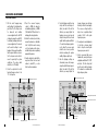
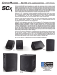
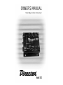
OWNER’S MANUAL
Two-Way Active Crossover
®
Model 202
CROSSOVER MOUNTING AND CONNECTIONS
TABLE OF CONTENTS
Crossover Mounting and Connections . . . . . . . . . . . . . . . . . .Page 1
Crossover Adjustments . . . . . . . . . . . . . . . . . . . . . . . . . . . .Page 2-3
Specifications . . . . . . . . . . . . . . . . . . . . . . . . . . . . . . . . .Page 4
Limited Two Year Consumer Warranty . . . . . . . . . . . . . . . . .Page 5
CONGRATULATIONS
Thank you for choosing a Directed signal
processor. Directed has been the leader
in high-quality and innovative security
products in the U.S. since 1990. Now
we introduce to the car audio industry
the same winning formula - products that
meet the stringent standards of today's
mobile electronics enthusiast yet priced
for anyone's budget. Featuring variable
crossover settings and 30 volt-driven
balanced circuits for more headroom
with 6 volt outputs, this Directed signal
processor will satisfy every music lover's
needs for years to come.
Your Directed signal processor comes
with a two year limited warranty if it is
installed by an authorized DEI dealer.
Please save your sales receipt and refer
to the warranty section of this manual
for complete details.
WARNING
High-powered car audio
systems may produce
sound pressure levels that
exceed the threshold at which hearing
loss may result.
They may also impair a driver’s ability to
hear traffic sounds or emergency vehicles. Use common sense and practice
safe listening habits when listening to
your audio system.
© 1999 Directed Electronics, Inc
1. Please read the owner's manual
carefully before you install the
crossover.
2. Disconnect the battery ground
terminal prior to making any
electrical connections.
3. Pick a mounting location that will
provide adequate access and ventilation and protect the crossover
from heat, moisture, and dirt.
When mounting the unit to the
floor pan or a fire wall, check both
sides for any hazards or obstructions such as gas tanks, fuel or
brake lines, and wiring harnesses.
4. Avoid sharp metal areas when
routing cables to the signal
processor, and run RCA cables away
from power cables and other potentially noisy car harnesses.
5. Power - connect this terminal to a
constant +12V source. The battery
+12V terminal of the amplifier or
the constant +12V supply to the
head unit are good locations for this
connection.
6. Ground - connect this terminal to
the car chassis. Make sure your
chassis connection is secure by
© 1999 Directed Electronics, Inc
removing any paint at the ground
point, and using a crimped,
soldered terminal at the end of the
wire. Do not connect this terminal
to the ground terminal of an amplifier in the system.
7. Remote in - connect this terminal to
the amplifier remote output from
your head unit or signal source, if it
provides one. The remote terminal
of an amplifier is a good source for
this connection. This input requires
a switched +12V signal to activate
the crossover.
8. Remote out - Connect to remote
input of the amplifier(s).
9. RCA input - connect to RCA output
from radio or signal source. Always
use shielded RCA signal cables for
this input.
10. High-pass RCA output - connect to
the amplifier driving mid or high
frequency speakers using a shielded
RCA cable.
11. Low-pass RCA output - connect to
the amplifier driving subwoofers or
lower frequency speakers using a
shielded RCA cable.
1
CROSSOVER ADJUSTMENTS
Crossover filters
1. Pick the correct frequency range
switch settings for the high and lowpass filters. The X1 setting is used
for subwoofer and mid-bass
crossover applications. Use the X10
setting when using the model 202
for mid-bass/midrange and tweeter
crossover applications. You can also
use the switch settings to create
bandpass filtering with amplifiers
that incorporate built-in crossovers.
Set the low-pass mode switch to
mono if required by the system
architecture. The phase switch
should be set to 0° initially.
2. Preset the output levels for both
high and low-pass sections to the
12 o'clock position.
3. Preset the crossover frequency
controls to 100Hz for subwoofer
and mid-bass applications, or 500Hz
(5kHz with the X10 switch on) for
midrange/tweeter applications.
4. Activate the head unit, and slowly
increase the volume to a comfortable
level. Verify that sound is coming
out of each speaker in the system,
and that each speaker is reproducing
appropriate frequencies.
5. Turn the output level controls all the
way down. Raise the head unit
volume to about 80%, or a few
clicks down from maximum.
High-pass frequency range switch
6. Turn the high-pass output level up
slowly until the sound begins to
distort, then back it off until the
distortion goes away. Adjust the
high-pass crossover point up and
down, listening for the best sound
quality. Smaller speakers will distort
if too much low-frequency signal is
sent to them. The crossover point
should be set as low as possible
without over-driving the speaker
audibly at higher output levels.
7. Once the high-pass settings are
determined, increase the low-pass
output level until the bass begins to
distort, then back it off until the
distortion goes away. Adjust the
low-pass frequency up and down
listening for the best sound quality.
The crossover setting should be
kept as low as practical without
creating a "hole" in the system
frequency response.
8. You may have to make adjustments
to the high or low-pass output
levels to keep the overall system
frequency response smooth.
9. Listen to some music that you are
familiar with, moving the low-pass
output phase switch from 0° to 180°
and back. Pick the setting that
gives the most realistic integration
of the subwoofer or mid-bass with
higher frequency drivers.
High-pass crossover frequency control
High-pass output level control
Low-pass phase inversion switch
Low-pass mode selector switch
Power indicator LED
2
Bass equalization control
Low-pass frequency
range switch
Low-pass output level control
© 1999 Directed Electronics, Inc
© 1999 Directed Electronics, Inc
Low-pass crossover
frequency control
3
SPECIFICATIONS
LIMITED TWO YEAR CONSUMER WARRANTY
• Crossover Slope
12 dB/octave
• Crossover Frequency
35Hz-500Hz, X1 mode
350Hz-5kHz, X10 mode
• Bass equalization
-0,+12dB@40Hz,variable
• Frequency response
10Hz-50kHz, ± .5 dB
• THD
0.02%
• Signal-to-Noise Ratio
100dB(high-pass),90dB(low-pass)
• Separation
75 dB
• Input Sensitivity
200mV ~ 6V RMS
• Input Impedance
47k ohm
• Output Impedance
470 ohm
• Maximum Output Voltage
8V RMS
• Supply Voltage
9VDC to 16VDC
• Dimensions (mm)
162 W x 40 H x 125 D
FEATURES
• 30 volt balanced circuit design
• Low-noise J-FET op-amps
• X10 crossover frequency range switches
• Mono/stereo low-pass output switch
• Phase inversion low-pass output switch
• Separately adjustable filters for greater tuning flexibility
• Remote out with delay to turn on amplifiers.
Directed Electronics, Inc. (DEI) promises to
the original purchaser, to replace this
product should it prove to be defective in
workmanship or material under normal use,
for a period of two years from the date of
purchase by the dealer as indicated by the
date code marking of the product PROVIDED the product was installed by an
authorized DEI dealer. During this two year
period, there will be no charge for this
replacement PROVIDED the unit is returned
to DEI, shipping pre-paid. If the unit is
installed by anyone other than an authorized DEI dealer, the warranty period will be
1 year from date of purchase by the dealer
as indicated by the date code marking of
the product. During this 1 year period, there
will be no charge for this replacement PROVIDED the unit is returned to DEI, shipping
pre-paid. This warranty is non-transferable
and does not apply to any unit that has
been modified or used in a manner contrary
to its intended purpose, and does not cover
damage to the unit caused by installation or
removal of the unit. This warranty is void if
the product has been damaged by accident
or unreasonable use, neglect, improper
service or other causes not arising out of
defects in materials or construction. ALL
WARRANTIES INCLUDING BUT NOT
LIMITED TO EXPRESS WARRANTY,
IMPLIED WARRANTY, WARRANTY OF MERCHANTABILITY, FITNESS FOR PARTICULAR
PURPOSE, AND WARRANTY OF NONINFRINGEMENT OF INTELLECTUAL
PROPERTY ARE EXPRESSLY EXCLUDED TO
THE MAXIMUM EXTENT ALLOWED BY
LAW, AND DEI NEITHER ASSUMES NOR
AUTHORIZES ANY PERSON TO ASSUME
FOR IT ANY LIABILITY IN CONNECTION
WITH THE SALE OF THE PRODUCT. DEI
HAS ABSOLUTELY NO LIABILITY FOR ANY
AND ALL ACTS OF THIRD PARTIES
INCLUDING ITS AUTHORIZED DEALERS OR
INSTALLERS. Unit must be returned to DEI,
postage pre-paid, with: consumer's name,
telephone number, and address, authorized
dealer's name and address, and product
description. IN ORDER FOR THIS WARRANTY TO BE VALID, YOUR UNIT MUST BE
SHIPPED WITH PROOF OF INSTALLATION
BY AN AUTHORIZED DEI DEALER. ALL
UNITS RECEIVED BY DEI FOR WARRANTY
REPAIR WITHOUT PROOF OF DEI DEALER
INSTALLATION WILL BE COVERED BY THE
LIMITED 1 YEAR PARTS AND LABOR WARRANTY. Note: This warranty does not cover
labor costs for the removal and reinstallation of the unit. BY PURCHASING THIS
PRODUCT, THE CONSUMER AGREES AND
CONSENTS THAT ALL DISPUTES BETWEEN
THE CONSUMER AND DEI SHALL BE
RESOLVED IN ACCORDANCE WITH CALIFORNIA LAWS IN SAN DIEGO COUNTY,
CALIFORNIA.
• Gold-plated power terminals and RCA jacks
4
© 1999 Directed Electronics, Inc
© 1999 Directed Electronics, Inc
5
OTHER PRODUCTS AVAILABLE FROM:
®
•
•
•
•
CLASS D MONO AMPLIFIERS
2 CHANNEL AMPLIFIERS
4 AND 5 CHANNEL AMPLIFIERS
SIGNAL PROCESSORS
•
•
•
•
TUBE SUBWOOFERS
POWERED SUBWOOFERS
SINGLE AND DUAL VOICE COIL SUBWOOFERS
COAXIAL SPEAKERS
•
•
•
SINGLE AND DUAL VOICE COIL SUBWOOFERS
COAXIAL SPEAKERS
COMPONENT SPEAKER SYSTEMS
•
•
SINGLE AND DUAL VOICE COIL DIE-CAST SUBWOOFERS
COMPONENT NEODYMIUM SPEAKER SYSTEMS
•
SINGLE AND DUAL VOICE COIL DIE-CAST SUBWOOFERS
•
•
•
•
•
HIGH PERFORMANCE POWER CABLES
PREMIUM SPEAKER/AUDIO CABLES AND ADAPTERS
POWER CAPACITORS
GOLD-PLATED POWER DISTRIBUTION AND FUSING BLOCKS
GOLD-PLATED POWER AND SPEAKER TERMINALS
Always use a
© 1999 Directed Electronics, Inc • Vista, CA 92083 • All Rights Reserved
DEI is a proud member of
G202 11/99