1
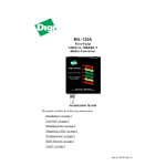
MIL-170TRM
10BASE-FL to 10BASE-T
Media Converter for Digi's
Media Conversion System
Thumbscrews
MDI-X MDI
MIL- 10BASE-T
170TRM
TP
FX
ACT ACT
TP
FX
LINK LINK
10BASE-FL
TX
RX
Installation Guide
This guide includes the following:
“Introduction” on page 2
“Features” on page 2
“Installation” on page 2
“MDI-X/MDI Switch” on page 3
“Link Sentry Configuration” on page 3
“Indicators” on page 4
“Specifications” on page 4
“Operating Conditions” on page 5
“Legal Declaration” on page 6
Doc #: 90000096 Rev. A
Install Guide
A b o u t th is M anual
This document covers the MIL-170TRM media converter module. The terms
“MIL-170,” MIL-170TRM,” and “converter” are used throughout this document
to describe the MIL-170TRM.
In tro d u ctio n
The MIL-170TRM is one of a series of modules designed to be installed into Digi's
Media Conversion System. This half-/full-duplex device converts optical signals
to electrical and vice-versa.
The device has a signal capability of transmitting up to 15 km (subject to fiber
budget and collision domain restrictions). This module also has the Link Sentry
feature.
F ea tu re s
• One RJ-45 (UTP) connector
• One single-mode, ST connector
• Link Sentry feature
• Diagnostic LEDs
• Management ready–supplied by the optional SNMP modules (MIL-4650 and
MIL-4655)
• Power supply equipped on the rack mount chassis
In stalla tio n
Do the following to install the MIL-170TRM into a redundant rack mount chassis:
1. Make any configuration changes to the module (i.e., DIP switch settings).
2. Remove the screws securing the faceplate and remove it from the chassis.
3. Slide the module into the slot through the guide rails.
4. Insert the module into the card-edge connector (port bay). Make sure it is
seated firmly.
5. Secure the module with the two thumbscrews located on the faceplate of the
unit.
The unit is now ready for network connections.
Model: MIL-170TRM
2
Install Guide
MD I-X /MD I Swit ch
The MDI-X/MDI switch allows for quick configuration of the 10BASE-T port.
Cables used when the switch is in the MDI-X position (the “left” position):
• For a hub/repeater, use a swap cable (pins are connected 1 to 3, 2 to 6, 3 to 1,
and 6 to 2)
• For a workstation/PC, use a straight-through cable (pins are connected 1 to 1,
2 to 2, 3 to 3, and 6 to 6)
4
3
2
1
4-pin DIP Switch
LEDs
(4 total)
RJ-45 Female
Connector
MDI-X/MDI
Switch
ST-Type
Connectors
Figure 1.Inside of the MIL-170TRM
Cables used when the switch is in the MDI position (the “right” position):
• For a hub/repeater, use a straight-through cable (pins are connected 1 to 1, 2 to
2, 3 to 3, and 6 to 6)
• For a workstation/PC port, use a swap cable (pins are connected 1 to 3, 2 to 6,
3 to 1, and 6 to 2)
L in k S e n tr y Configurat ion
The Link Sentry feature on the MIL-170TRM is configured through a 4-position
DIP switch (refer to Figure 1). Default setting for the DIP switches: All switches
are in the “up” position.
Link Sentry allows users to add new management tools to the network. When
enabled, it monitors the selected receiver port and, if the Link test signal is not
seen, the unit will stop sending a signal through the selected transmit port.
Model: MIL-170TRM
3
Install Guide
The following table shows which Link Sentry feature is enabled:
Table 1: Link Sentry Features
Switch
Note:
Losing Link on RX of
Stop sending Link on TX of
1 (down)
Fiber port
Fiber port
2 (down)
UTP port
UTP port
3 (down)
UTP port
Fiber port
4 (down)
Fiber port
UTP port
For two MIL-170s used back-to-back and UTP-to-UTP, all DIP switches must be enabled
(in the “down” position) on the first MIL-170. On the second MIL-170, enable switches 1
and 4 (in the “down” position).
Default setting for Link Sentry: All switches set in the “up” position (disabled). When using
the SNMP module to control the Link Sentry feature, leave the switches in the default
mode (“up”).
In d ic a to rs
There are four LEDs, including:
TP/ACT: Receiving packets from the 10BASE-T port
TP/LINK: There is an active connection on the 10BASE-T port
FX/LINK: There is an active connection on the 10BASE-FL port
FX/ACT: Receiving packets from the 10BASE-FL port
S p ec ifi ca tions
R J-45 : MDI
• Pin 1 = Transmit Data +
• Pin 2 = Transmit Data • Pin 3 = Receive Data +
• Pin 6 = Receive Data R J-45 : MDI- X
• Pin 1 = Receive Data +
• Pin 2 = Receive Data • Pin 3 = Transmit Data +
• Pin 6 = Transmit Data -
Model: MIL-170TRM
4
Install Guide
3 4
1 2
5 6 7 8
Figure 2.RJ-45 Pinouts
F ib e r S p ecificat ions: ST connect or
• 1300 nm single-mode fiber
• 8 or 9/125 µm single-mode fiber
• Launch power: -19 dBm
• Receive sensitivity: -36 dBm
Op era tin g Condit ions
Table 2: Recommended Operation Conditions
Parameters
Model: MIL-170TRM
Minimum
Maximum
Operating Temperature
+5° C
+50° C
Humidity: Non-condensing
10%
95%
Signal Output Load
35 ohm
75 ohm
Supply Voltage
4.75 V
5.25 V
5
L eg al D ecla ra t ion
Regulator y Approvals
•
•
•
•
•
FCC Class A
UL 1950
CSA 22 No. 950
EN60950
CE
– EN55022 Class B
– EN50082-1
Canadian EMI Notice
This Class A digital apparatus meets all the requirements of the Canadian Interference-Causing
Equipment Regulations.
Cet appareil numérique de la classe A respecte toutes les exigences du Règlement sur le matériel
brouilleur du Canada.
European Notice
Products with the CE Marking comply with both the EMC Directive (89/336/EEC) and the Low Voltage
Directive (73/23/EEC) issued by the commission of the European Community. Compliance with these
directives implies conformity to the following European Norms:
•
•
•
EN55022 (CISPR 22) - Radio Frequency Interference
EN50082-1 (IEC801-2, IEC801-3, IEC801-4) - Electromagnetic Immunity
EN60950 (IEC950) - Product Safety
Five-Year Limited Warranty
Digi International warrants to the original consumer or purchaser that each of its
products, and all components thereof, will be free from defects in material and/or
workmanship for a period of five years from the original factory shipment date. Any
warranty hereunder is extended to the original consumer or purchaser and is not
assignable.
Digi makes no express or implied warranties including, but not limited to, any implied
warranty of merchantability or fitness for a particular purpose, except as expressly set
forth in this warranty. In no event shall Digi be liable for incidental or consequential
damages, costs, or expenses arising out of or in connection with the performance of the
product delivered hereunder. Digi will in no case cover damages arising out of the
product being used in a negligent fashion or manner.
To Contact Digi
For prompt response when calling for service information, have the following information ready:
•
•
•
Product serial number and rev.
Date of purchase
Vendor or place of purchase
Reach Digi Technical Support at 408/744-2751
Or E-mail at “[email protected]”
Address: 1299 Orleans Drive
Sunnyvale, CA 94089
Voice:
408/744-2775
Fax:
408/744-2793
E-mail: [email protected]
Doc #: 90000096 Rev. A