1
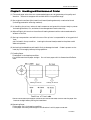
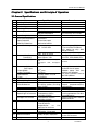
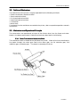
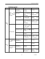
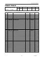
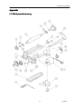
CITIZEN
Service Manual
Model : LT-286
Line Thermal Printer
Rev. 1.00 Newly issued on Jan.16.1998
Japan CBM Corporation
Information Systems Div.
LT-286 Service Manual
Preface
This booklet explains the operational principle, procedure for maintenance work, and others
of the line thermal printer, LT-286, and is intended for maintenance personnel in fields.
Characteristics
LT-286 is a line dot type small-sized printer provided with a line thermal head. This
printer
has been developed for the output terminals for POS terminals, measuring and analyzing
equipment, medical equipment, communication data equipment, and the like, and is smallsized as far as possible.
* Small- sized and light-weighted printer
* Print as fast as up to 400 dot line/sec.
* Clear print by high resolution of 8 dot/mm.
* Employment of paper 58 mm in width.
* Employment of a very durable head.
* High reliability by simple mechanism.
2
CITIZEN
LT-286 Service Manual
CONTESTS
PREF
REFACE ................................................................
................................................................................................
................................................................................................
...........................................................................
...........................................2
........... 2
CHARACT
ARACTERI
ERISTICS ................................................................
................................................................................................
.........................................................................................
.........................................................2
......................... 2
CHAPTER
PTER 1 HANDLING AND MAINTENANCE OF PR
PRINTER ................................................
................................................4
................ 4
CHAPTER
PTER 2 SPECI
ECIFICAT
CATIONS AND PRINCIPLE
PLE OF OPERAT
ERATION .......................................
.......................................5
....... 5
2-1 GENERAL
ERAL SPECI
ECIFICAT
CATIONS ............................................................................................................. 5
2-2 OUTLI
TLINE OF MECH
ECHANISM............................................................................................................. 6
2-3 MECH
ECHANISM AND OPERAT
ERATIONAL PRINCIPLE
PLE............................................................................... 6
ssiion Mechanism Block ............................................................................ 6
2-3-1 Power Transmiss
2-3-2 Sensor Mechanism Block .................................................................................................... 7
2-3-3 Print Head Mechanism Block ............................................................................................. 8
eed
2-3-4 Paper Fee
d Mechanism Block .......................................................................................... 10
2-4 CONNEC
NNECT
ECTING TERM
ERMINAL ............................................................................................................ 11
2-4-1 Thermal Head Terminal ................................................................................................... 11
nne
2-4-2 Motor and Sensor cco
onn
ector ............................................................................................. 14
CHAPTER
PTER 3 DISASSE
SSEMBLING AND REASS
REASSE
SSEMBLING ..........................................................
..........................................................15
.......................... 15
3-1 TOOL
OOL LIST.................................................................................................................................... 15
3-2 PROCED
CEDURE FOR DISASSE
SSEMBLING ............................................................................................. 15
3-3 PROCED
CEDURE FOR REASS
EASSE
SSEMBLING .............................................................................................. 15
sse
lin
3-3-1 Procedure for Reass
embli
ng Printer Body ..................................................................... 16
3-3-2 Procedure for Reasse
ssemblin
ling Platen Rolle
ller Unit ............................................................ 25
CHAPTER
PTER 4 TROUBLE-SHOOT
OOTING ................................................................
..........................................................................................
..........................................................26
.......................... 26
4-1 PROCED
CEDURE FOR REPAIRS .......................................................................................................... 26
4-2 GUIDE TO REPAIR ....................................................................................................................... 27
4-2-1 Guide to repair 1/2................................................................................................................ 27
4-2-2 Guide to repair 2/2................................................................................................................ 28
CHAPTER
PTER 5 PART
ARTS LIST ................................................................
................................................................................................
.............................................................................
.............................................29
............. 29
APPE
PPENDIX ................................................................
................................................................................................
................................................................................................
.......................................................................
.......................................30
....... 30
LTLT-286 DISASSE
SSEMBLE DRAW
RAWING ......................................................................................................... 30
3
CITIZEN
LT-286 Service Manual
Chapter 1 Handlin
ling and Maintenance of
of Printer
(1) The use of paper other than our recommended paper can not guarantee print quality and
duration. Be sure to use paper with a width within the specified range.
(2) Do not give the surface of the head circuit board (heating elements) a mechanical shock
(including penetration of foreign matters).
(3) In handling the printer, take anti-static measures and ground the human body to protect
the heating elements, ICs, and others from damage due to static electricity.
(4) Wipe off lightly dirt stuck on the surface of heating elements with a cotton swab soaked in
ethanol or the like.
(5) During transportation and while the use of the printer is suspended for a long period of
time,
put the head in the up condition. Leaving the thermal head pressed to the platen could
deform the platen.
(6) Activating the dewed thermal head is likely to damage the head. If dew is present on the
head, dry it thoroughly before printing operation.
(7) Feeding Paper
* Feed paper in the head-up condition.
*Cut the forward end of paper straight. Do not insert paper with its forward end fluffed or
bent.
* When the forward end of paper comes out of the thermal head, confirm that the paper has
been set straight before putting the head down.
(8) Removing Paper
* Take paper out in the head-up condition.
* Take paper out slowly and straight to the direction in which paper comes out.
4
CITIZEN
LT-286 Service Manual
Chapter 2 Specifications and Principle of
of Operation
2-1 General Specifications
Item
1
2
3
4
5
Printing Method
Total number of dot
Dot density
Printing width
Printing Speed
6
7
Paper feed pitch
Detection Function
Print Head Temperature
Paper Detection
Head Up Detection
8
9
10
11
12
13
14
Operation Voltage Range
Specifications
Thermal Line Dot Method
384 dots/line
8 dots/mm
48.0 mm
150 dot lines/second
400 dot lines/second
0.125mm
Thermistor
Photo interrupter
Mechanical switch
Recommended
Roll Paper
Paper Width
Paper Thickness
Manufacture
Type
Paper Feed Force
Paper Holding Force
Head Life
Pulse Resistance
Wear Resistance
Environment
Operating Environment
Vdd DC4.75~5.25V
Max. Approx. 2.3A
Max. Approx. 3.3A
Max.Approx.
0.3A
Max.Approx.
0.5A
0.5A,
Ave.Approx.
0.8A,
Ave.Approx.
58+0-1 mm
60~72mm
Shinohji Seishi Co.,Ltd.
KF50-HAD
50g or more
80g or more
15
Vibration resistance
16
Shock-resistance
17
Outer-Dimension
Weight
Approx. 82g
18
Two motor steps
VH=5V, 142W,64dots,25°C
VH=7.2V, 142W,64dots,25°C
VH=5V
VH=7.2V
Printing face must be the
surface of the roll paper.
Between paper and core
must be non adhesion.
Roll paper diameter must be
less than f83mm.
50 million pulses (Printing Normal temperature(25°C)
duty :12.5%)
and humidity.
Rated energy, recommended paper
50 Km
Temperature: 0~45°C
Humidity:35~85%
Temperature:-20~60°C
Humidity:10~90%
1G, Frequency 5 to 100Hz in
three directions
perpendicular
to
the
machine, for one hour
60G, 11ms
6 direction, 1 time each
75(W)´56.5(D)´21(H)mm
Storage Environment
5V, Head temp.>30°C,£64 dots
7.2V, Head temp.>30°C,£64 dots
Typ. Voltage of Ni-Cd and
Li-Ion must be 7.2V(Max).
8.5V would be only after
charge a battery.
VH DC4.2~8.5V
Consumption Current
Head(VH)
Motor(VH)
Remarks
5
Printing guarantee: 5 to 40°C
No condensation
Machine stored with head in
raised condition
Excluding paper feed knob, Head
up lever and Connectors
CITIZEN
LT-286 Service Manual
2-2 Outlin
line of
of Mechanism
The mechanism of this printer is roughly separated into the following six blocks.
* Power transmission mechanism block.
* Sensor mechanism block.
* Print head mechanism block.
* Paper feed mechanism block.
* Frame block.
* Motor block.
For external circuits and others connected to the printer, refer to respective operation manuals
and the like.
2-3 Mechanism and Operational Principle
The construction and operational principle of four blocks other than the frame and motor
blocks in the above-mentioned six mechanism blocks are described in the following.
2-3-1 Power Transmissi
ssion Mechanism Block
This mechanism block is located at the left side of the printer. Motor drive is to transmitted to
the platen through the motor gear fixed to the motor gear, the 1st reduction gear, 2nd
reduction gear, and platen gear. The platen is rotated by this drive.
6
CITIZEN
LT-286 Service Manual
2-3-2 Sensor Me
Mechanism Block
This sensor mechanism block is composed of a head-up and paper sensors.
(1) Head-up sensor
This is a sensor to detect a head up/down condition. Activating the head in the head-up
condition is likely to damage the head or decrease the duration significantly. This head-up
sensor is used to control such cases. Operating the head-up lever the head-up sensor fixed
to the right side of the frame, this sensor operates.
(2) Paper sensor
This is a sensor to detect the presence/absence of paper. Activating the head when paper is
not set is likely to damage the head or decrease the duration significantly. This paper
sensor is used to control such cases.
7
CITIZEN
LT-286 Service Manual
2-3-3 Print Head Mechanism Block
A thermal head is used as the print head of this printer. The thermal head is composed of
heating elements and a head driver to drive and control the elements.
(1) Outline of drive control
Serial print data input from DATA IN (DI) are transferred to the shift register in
synchronization with CLOCK (CP), and stored in the latch register by the LATCH (LA)
signal. When the gate is turned ON by the head activation signal (print commands, STB1
to 6), the heating element corresponding to the stored print data is activated, and this heat
prints on paper.
8
CITIZEN
LT-286 Service Manual
(2) Head separation processing
There are six thermal head strobes. The relationship between the strobe and heating
element positions are as follows:
STB No.
1
2
3
4
5
6
Elements No.
1~64
65~128
129~192
193~256
257~320
321~384
Number of dots /STB
64
64
64
64
64
64
(3) Print data and print location
Data No. 1 to 384 of 384 bits transferred by DATA IN (DI) are printed on the location shown
in the following figure.
9
CITIZEN
LT-286 Service Manual
(4) Up/Down mechanism of print head
The print head is normally held in the down condition. When the head-up lever is pushed
up, the cam of the lever rotates to push the head SP (head spring) down. The projection of
the head SP inserted into the groove provided on the heat sink separates the print head
from
the platen to put the print head in the up condition.
2-3-4 Paper Feed
eed Mechanism Block
For the paper feed mechanism, the platen, that is the core of the paper feed mechanism, rotates
being driven by the power transmission mechanism. Paper is supplied from the rear side of
the printer, and transferred to the upper part again through between the platen and head.
Then, the paper is pressed to the platen by the head, and is sent as the platen rotates.
10
CITIZEN
LT-286 Service Manual
2-4 Conne
nnecting Terminal
The connecting terminal is composed of two connectors. Details are described in the following.
Function
Thermal head
“Head up” sensor
Paper sensor
Motor
Number
of pins
28
10
Type
Connector for
FPC/FFC(Pitch:1.25mm
)
51021-1000
(Molex)
Recommended mated
connector
Refer to reference plan of
applicable cable
53047-1010
53048-1010
(Molex)
2-4-1 Thermal Head Terminal
The arrangement of thermal head connectors and the function of each terminal are as follows:
11
CITIZEN
LT-286 Service Manual
(1) Terminal Arrangement of Thermal Head Connectors
12
CITIZEN
LT-286 Service Manual
(2) Pin layout of thermal head connector
Pin
No.
1
2
3
4
5
6
7
8
9
10
11
12
13
14
15
16
17
18
19
20
21
22
23
24
25
26
27
28
Signal name
VH
VH
VH
DATA OUT
LATCH
CLOCK
Vdd
STB1
STB2
STB3
TERMISTOR
THERMISTOR
P-GND
P-GND
P-GND
P-GND
P-GND
L-GND
NC
NC
STB4
STB5
STB6
NC
DATA IN
VH
VH
VH
Function
Power for thermal head
Power for thermal head
Power for thermal head
Print data serial output
Print data latch signal
Clock signal for data transfer
Power for thermal head driver
Strobe 1
Strobe 2
Strobe 3
Thermistor
Thermistor
POWER GND
POWER GND
POWER GND
POWER GND
POWER GND
LOGIC GND
NO CONNECTION
NO CONNECTION
Strobe 4
Strobe 5
Strobe 6
NO CONNECTION
Print data signal input
Power for thermal head
Power for thermal head
Power for thermal head
13
CITIZEN
LT-286 Service Manual
2-4-2 Motor and Sensor co
conne
nnector
The pin layout of the each sensors and motor connector and the name of each pin are as follows.
Pin layout of motor and sensors connector
Pin No.
1
2
3
4
5
6
7
8
9
10
Pin name
Remarks
A
B
A
B
Photo-transistor collector
Photo-transistor emitter
LED anode
LED cathode
Head-up sensor output
Head-up sensor output
Motor
Paper sensor
Head up sensor
Sensor connector circuit diagram
14
CITIZEN
LT-286 Service Manual
Chapter 3 Disasse
ssemblin
ling and Reasse
ssemblin
ling
Pay attention to the following matters in maintenance work
Caution:
(1) Do not disassemble, reassemble, nor adjust the printer without reasons, if it works
normally.
Do not undo carelessly screws for fixing components in particular.
(2) Upon completion of inspections, be sure to check the printer for an anomaly before turning
power on.
(3) Never print without setting paper to the printer.
(4) Confirm that paper has been set normally.
(5) Be careful not to leave parts, screws, or others used for maintenance work in the printer.
(6) In handling the print head, do not use gloves that are easy to generate static electricity.
(7) In disassembling and reassembling work, check cables and cords for damage or defects, and
do not lay them forcibly.
3-1 Tool
ool List
* (+) Screwdriver (No. 0 and 2).
* Pincette.
* Mini-radio-plier.
* Oil brush.
* Mini-nipper.
* Plier exclusive for grip rings.
3-2 Procedure for Disasse
ssemblin
ling
For disassembling the printer, remove parts from the frame according to 3-3 "Procedure for
Reassembling", but in the opposite order.
3-3 Procedure for Reasse
ssemblin
ling
Separating into reassembling of the printer body and that of the platen roller unit, procedure
for reassembling is explained in the following. Parts names used in the explanation are based
on those in shown in "Parts List" in Chapter 5. These part names are commonly used over
this service manual.
15
CITIZEN
LT-286 Service Manual
3-3-1 Procedure for Reasse
ssemblin
ling Printer Body
(1) Incorporate the motor assembly to the frame.
(2) Fix the motor assembly to the frame by two fitting screws (M2 x 3).
(3) Incorporate the head-up sensor to the right side of the frame.
the
direction, and fix it by a fitting screw (M1.7 x 6).
Set the head-up sensor in
Caution:
In incorporating, check the leaf of the head-up sensor for deformation, loose fitting, and cracks,
16
CITIZEN
LT-286 Service Manual
(4) Incorporate the paper sensor to the bottom surface of the frame.
Caution:
Be careful not to break the cover of lead wires in incorporating work.
(5) Fix lead wires for the motor assembly with binder wires for leads not to get loose.
17
CITIZEN
LT-286 Service Manual
(6) Incorporate the earth spring to the frame by a fitting screw (M2 x 5).
(7) Apply grease(Mori-coat EM-10L )to two gear pivots on the left side of the frame.
18
CITIZEN
LT-286 Service Manual
(8) Incorporate the 1st reduction gear so that it may engage with the gear of the motor
assembly.
(9) Incorporate the 2nd reduction gear so that it may engage with the 1st reduction gear.
Caution:
In incorporating, be careful about the direction so that the larger gear comes to the upper side.
19
CITIZEN
LT-286 Service Manual
(10) Apply Mori-coat EM-10L to two gear pivots in which gears have been incorporated.
(11) Put and incorporate the grip ring to the stepped portion on the tip of the pivot for the 2nd
reduction gear fully to the root of the step using a plier exclusive for grip rings.
Caution:
(a) Inserting grip rings requires the use of an exclusive plier.
(b) The openness of the grip ring in insertion should not be much more than the outside
diameter of the gear pivot. Much openness decreases the spring force to reduce the
securing force of the grip ring.
20
CITIZEN
LT-286 Service Manual
(12) Put the lever holder in the frame.
Caution:
Be careful about the direction of inserting the lever holder so that the arc-shaped part comes to
the paper insertion inlet side.
(13) Apply Mori-coat EM-10L to the arc-shaped portion of the lever holder and the arc-shaped
portions of five frame ribs.
21
CITIZEN
LT-286 Service Manual
(14) Insert the head-up lever from the right side of the frame.
Caution:
Insert the lever so that the sectional form of the shaft of the head-up lever and that of the hole
on the frame agree.
(14) Incorporate the thermal head assembly from the bottom side of the frame. First, insert it
from the hole on the side on which the motor is fitted.
Caution:
In inserting the assembly, be careful not to deform the earthing spring fitted on the right side
of the frame.
Caution on Handling Thermal Head Assembly:
(a) Do not touch the print surface of the head with bear hands.
(b) After the head is incorporated, keep the head-up lever to the up condition all the time except
during print time so that the platen should not touch the head.
22
CITIZEN
LT-286 Service Manual
(16) Apply Mori-coat EM-10L to the area of the head SP where the head-up lever touches it
(the shaded area in the following figure).
(17) Inserting the projection at the center of the head SP to the groove at the center of the
thermal head assembly from the bottom side of the frame, insert the head SP to two shafts
of the frame.
23
CITIZEN
LT-286 Service Manual
(18) Fix the head SP by a fitting screw (M4 x 8).
Caution:
Fasten the fitting screw carefully since the screw, for which a tapping screw is used, is likely to
be fastened diagonally.
(19) Put the platen roller unit in the frame. Push the lever of the platen bushing down by 90
degrees in order to hang it to the claw of the frame.
This is the end of reassembling work of the printer body.
24
CITIZEN
LT-286 Service Manual
3-3-2 Procedure for Reasse
ssemblin
ling Platen Rolle
ller Unit
(1) Insert platen bushings to both sides of the platen.
(2) Fix the inserted platen bushings at both sides by two E rings.
(3) Push and insert the knob to the right side shaft of the platen. In this time, make the D-cut
portion of the shaft agree with the D-shaped hole of the knob.
(4) Push and insert the platen gear to the left side shaft of the platen. In this time, make the
D-cut portion of the shaft agree with the D-shaped hole of the gear.
Caution:
(a) In incorporating the platen gear, be careful about its direction so that the stamped side
comes to the bushing side.
(b) Use a mini-radio-plier or pincette to fix E rings.
This is the end of reassembling the roller unit.
25
CITIZEN
LT-286 Service Manual
Chapter 4 Trouble-Shoot
ooting
4-1 Procedure for Repairs
When the printer is out of order, observe the phenomenon of the trouble carefully to specify
what is the trouble according to 4-2 "Guide to Repairs." Then, repair it according to the
prescribed method.
* Phenomenon
Look for the phenomenon of the trouble in the column of "Phenomenon" in the following list.
In the case of phenomena more than one, take up all applicable items. This can specify
hidden defects.
* Causes
Possible causes are listed as many as possible. Assume possible causes, and specify the cause
from the check methods mentioned in the next column.
* Check Method
This mentions check methods to specify the cause of the trouble.
* Repair Method
Repair the failure according to the method mentioned in this column.
Repairs done according to the above-mentioned procedure can reduce wrong judgment and
secure effective trouble-shooting.
26
CITIZEN
LT-286 Service Manual
4-2 Guide to Repair
4-2-1 Guide to repair 1/2
Phenomenon
Cause
Check method
to Measure
Repair method
power If out of rating,
supply voltage with correct
power
tester or oscilloscope. supply circuit.
Power supply
head poor.
Print impossible Thermal
head Check
connected Connect connector
connection poor.
condition
of correctly.
connector.
Thermal
head
assembly poor.
to Measure
power If out of rating,
power
supply voltage with correct
tester
or supply circuit.
oscilloscope.
Power supply
head poor.
Print
Light-colored
Print
Trouble
Dots missing
Thermal
head
assemble poor.
Renew
thermal
head assembly.
foreign
matters Check if foreign Wipe
thermal matters stuck on matters off with
soft cloth soaked in
thermal head.
ethanol.
Thermal
head
Renew
thermal
assembly poor
head assembly.
Foreign
stuck on
head.
Power supply
head poor.
to Measure
power If out of rating,
power
supply voltage with correct
tester
or supply circuit.
oscilloscope.
Dirt
stuck
thermal head
on Check if dirt stuck Wipe dirt with soft
on thermal head.
cloth soaked in
ethanol
Check if paper that Use paper that
meets specification meets specification.
is used.
Print very dirty
Print
quality poor
Renew
thermal
head assembly.
Paper poor
27
CITIZEN
LT-286 Service Manual
4-2-2 Guide to repair 2/2
Phenomenon
Cause
Paper
feed Power supply to
motor does not motor poor
work, or works
unstably
Lead wire broken in
motor assembly
Paper
Feed
Poor
Check method
Repair method
Measure
power
supply voltage with
tester
or
oscilloscope.
Check conductivity
of lead wires in
motor assembly.
If out of rating,
correct
power
supply circuit.
connected Connect connector
Motor
connector Check
condition
of correctly.
(Terminal)
connector.
connection poor
If lead wire broken,
renew
motor
assembly.
Motor body poor
Measure
power If supply voltage is
renew
supply voltage with normal,
tester
or motor assembly.
oscilloscope.
Paper supply poor
Check
if
paper Set paper correctly.
jammed or broken
to get caught in
paper course.
Foreign
matters Check if foreign Remove
penetrated in gears
matters get caught matters.
No paper feed
foreign
in gears.
Gear damaged
Check
gear
damage.
Motor body poor
Measure
supply If supply voltage is
renew
voltage with tester normal,
motor assemly.
or oscilloscope.
Sensor
for Renew
gear.
damaged
connector Connect connector
connector Check
connection.
correctly.
Presence/absene (Terminal)
of paper not connection poor.
detected.
Paper sensor poor
Sensor
Poor
Renew
assembly.
sensor
connected Connect connector
Sensor
connector Check
condition
of correctly.
(Terminal)
connector.
Head down not connection poor.
detected.
Head up sensor poor Check actuator of If sensor is normal,
sensor
head up sensor for renew
assembly.
deformation.
28
CITIZEN
LT-286 Service Manual
Chapter 5 Par ts List
SERVICEPARTS LIST
MODEL: LT-286
RE
F
1
PARTS No.
REV
DATE
COMMENT
APPROVED
DRAWN
PAGE
0.00
’97.6.12
New version
Omata
Gonmori
1/1
DESCRIPTION
Flame
3
4
5
6
E8016-070
E8017-080
E8018-080
E8018-090
Motor Assy
Motor SMR30-2031-A
Head up sensor Assy
PE sensor Assy
9
10
E8019-090
E8019-100
12
13
14
15
QTY
1
DRAWING
No.
60-0214
1
(1)
(1)
(1)
25-0345
25-0344
1st Reduction gear
2nd Reduction gear
1
1
60-0210
60-0211
E8031-080
E8019-110
E8025-070
E8029-040
Platen roller
Platen gear
Platen bush
Knob
1
1
2
1
80-0319
60-0209
60-0208
60-0212
17
18
19
E8032-110
E8036-010
E8037-010
Head up lever
Lever holder
Earth spring
1
1
1
60-0213
60-0217
50-0200
24
E66000240
Thermal head KF2002-GF13F
1
10-0081
26
E8021-120
Head spring
1
50-0201
32
33
34
35
36
23G65872
23G65915
23G65880
23G65897
23G65908
Grip ring No.2
M4´8
M1.7´6
M2´5
M2´3
1
1
1
1
2
38
E2
E ring No.2
2
29
OTHERS
25-0348
CITIZEN
LT-286 Service Manual
Appe
ppendix
LTLT-286 disasse
ssemble drawing
30
CITIZEN