1
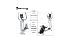
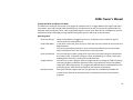
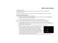
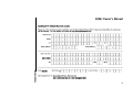
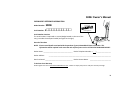
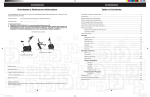
500Er Owner’s Manual 500Er Rear Drive Elliptical Owner’s Manual Diamondback Fitness release v.1 (11/09) 3 TABLE OF CONTENTS INTRODUCTION ................................................................................................................................................................................... 5 SAFETY INSTRUCTIONS & WARNINGS ................................................................................................................................................. 6 500Er ASSEMBLY INSTRUCTIONS ........................................................................................................................................................ 9 WORKOUT GUIDELINES .................................................................................................................................................................... 14 WORKOUT QUALITY AND QUANTITY ................................................................................................................................................ 17 500Er CONSOLE OVERVIEW .............................................................................................................................................................. 19 CONSOLE DISPLAY WINDOWS .......................................................................................................................................................... 20 CONSOLE KEYS .................................................................................................................................................................................. 22 CONSOLE OPERATION ....................................................................................................................................................................... 24 PROGRAMMING FEATURES .............................................................................................................................................................. 26 CLASSIC PROGRAMS ......................................................................................................................................................................... 28 TARGET HEART RATE PROGRAM ...................................................................................................................................................... 31 MAINTENANCE .................................................................................................................................................................................. 34 WARRANTY INFORMATION .............................................................................................................................................................. 35 PURCHASER’S REFERENCE INFORMATION ........................................................................................................................................ 39 4 500Er Owner’s Manual INTRODUCTION Congratulations on the purchase of your new Diamondback Fitness rear drive elliptical. You have made a great choice and are about to enjoy one of the most effective and technically‐advanced methods of low‐impact cardio‐ vascular exercise available today. Founded in 1991 as an off‐shoot of the legendary bicycle company, Diamondback Fitness was in many ways a complimentary addition to the Diamondback brand. One might even say this extension grew as a natural evolution…an evolution from classic outdoor bicycle usage, toward indoor‐based cycling and cross training. It turns out that many fitness enthusiasts were searching for ways to maintain conditioning during times of inclement weather or were simply looking for new and different cross‐training options. This trend still continues today, twenty years later, as the strong Diamondback brand resonates with both the boomers who grew up with the bicycles, as well as the younger generations riding them today. Diamondback Fitness continues to build upon this legendary brand identity by offering the cardio enthusiast a full line of upright exercise bikes, recumbents, and elliptical trainers, each offering superior value and quality in an intuitive and visually‐appealing design. Let’s just say, we are already planning our next twenty years. Thank you for choosing Diamondback Fitness. Diamondback Fitness 6004 South 190th Street, Suite 101 ● Kent WA 98032 ● Ph. 1.800.776.7642 ● Fax: 1.800.776.2073 For more information or questions regarding your equipment, please visit our website at DiamondbackFitness.com. 5 SAFETY INSTRUCTIONS & WARNINGS Every piece of Diamondback Fitness equipment is built for maximum safety and meets or exceeds all applicable domestic and international standards. However, certain precautions must be taken when operating any piece of fitness equipment. NOTE: Please read the entire owner’s manual before operating the unit. Save this manual for future reference. Cautions – For Safe Operation Keep hands and feet away from all moving parts and pinch points. If you have a history of heart disease, high blood pressure, diabetes, chronic respiratory diseases, elevated cholesterol, or if you smoke cigarettes or experience any other chronic diseases or physical complaints, consult with a physician before beginning any exercise program. If overweight, or above the age of 35, consult with your physician before beginning an exercise program. Pregnant women should consult with their physician before beginning an exercise program. If you experience dizziness, nausea, chest pains or other abnormal symptoms during exercise, stop the exercise session immediately and consult your physician. Consume water before, during and after each exercise session. Warnings – To Reduce the Risk of Injury to Yourself and Others To ensure proper functioning of your unit, do not install attachments or accessories not provided or recommended by Diamondback Fitness. Always wear proper clothing and shoes when exercising. User weight is not to exceed 300 pounds (136.0 Kg) for the 500Er. 6 500Er Owner’s Manual Keep children away from the unit. Hands and feet may become entangled with the moving parts and could result in serious injury. Place the unit in an area that will meet minimum clearance requirements: ▫ front & sides = 24 inches; rear = 12 inches. The unit is intended for indoor use only. Place the unit on a solid, level surface. Always adjust the leveling feet before using to ensure stability. Ensure all adjustment knobs and levers are fastened securely before using the unit and after making an adjustment. Use the handlebars when stepping on and off the unit. The unit is heavy. Do not attempt to move alone. Never operate the unit if it is damaged or broken. Contact your local authorized Diamondback Fitness Dealer for service. Please unplug the unit after exercising. Always unplug the unit from the power source before moving or servicing. Do not remove the covers or other components. Only Authorized Diamondback Fitness Dealers or Authorized Technicians should perform service on the unit. Assembly Assembly of all Diamondback Fitness products should be performed by a Diamondback Fitness Dealer or Authorized Technician. A significant amount of technical knowledge is required for the safe and complete assembly of the unit. Many retailers will offer delivery and assembly as part of the sales agreement. If this unit was sold unassembled (in the carton) and you do not feel you can perform the assembly successfully, please call the dealer for service. Service calls for improper assembly are not covered by the Warranty Policy and any associated charges will be the responsibility of the owner. 7 8 500Er Owner’s Manual 500Er ASSEMBLY INSTRUCTIONS 1. Install the four (4) stabilizer feet assemblies (A1 & A2) into the under‐side of the front and rear stabilizers. Thread all the way in. 2. Remove the eight (8) hex bolts (F1), eight (8) lock washers (F2), four (4) flat washers (F3) and four (4) curved washers (F4) from rear frame assembly B and set aside. 3. Remove the two (2) hex bolts G1 from the left and right sides of the console mast assembly (C) and set aside. 4. Stand the rear frame assembly (B) right‐side up and lay the console mast assembly (C) nearby. Join connectors D and E firmly to ensure a good connection. 5. Carefully stand console mast assembly C upright and join with the rear frame assembly (B). Ensure rear assembly (B) is fully inserted into the console mast receiver (C) by confirming the bolt holes are aligned. 6. Loosely install four (4) sets of parts F1, F2 and F3 into the sides of console mast assembly B and four (4) sets of parts F1, F2 & F4 into the top and underside of the mast assembly as per the figure to the left. Once all bolts are partially installed, tighten each firmly with the enclosed hex wrench. 9 7. Parts G2, G3, G4, G5 and G6 will arrive from pre‐assembled on the unit. Remove the four (4) hex bolts (G5) from the lower console mast front cover (G6) and set aside. Remove hex bolt G2 from the right side and set aside with the two (2) G1 hex bolts already set aside. 8. Gather the left (G3) and right (G4) lower console mast covers and bring together as a clamshell over the console mast/main frame union. Align covers with the mounting holes in the main frame and loosely thread the two (2) G1 hex bolts into place. Loosely install hex bolt G2 through the plastic cover G4 and into cover G3. 9. Install the lower console mast front cover (G6) by threading the four (4) hex bolts (G5) through the face and into parts G3 and G4. Do not over‐tighten. 10. Tighten hex bolts G1 and G2. Do not over‐ tighten and be aware of improper alignment as the plastic parts come together. 10 500Er Owner’s Manual Fig. 1. Fig. 2. Fig. 3. 11. The handlebar pivot fixing hardware will be pre‐installed on the console mast (C) as shown in Fig. 2. Remove bolt H1 and washer H2 from the left and right sides of the pivot axle, and set aside. 12. Washer I should remain in place, on the axle. 13. Handlebars (H6 & H7) are packaged with the pivot covers (H4) installed. Remove the four (4) hex fixing bolts (H5) and pivot cover (H4) from each handlebar as shown in Fig. 2. and set aside. 14. Ensure one piece of washer I is in place on each side of the axle as shown in Fig. 3. 15. Install the right (H6) and left (H7) handlebars by sliding each pivot over the axle. Pay careful attention to the alignment of the internal spacers as they may block the assembly from sliding onto the axle. Realign as necessary. 16. Fix each handlebar by reinstalling bolt H1 and washer H2, and tightening with the enclosed box wrench. 17. Replace the left and right pivot covers (H4) by reinstalling the hex bolts H5. 11 18. The forward pivots of the step arms (K2 & K3) will arrive with the fixing hardware pre‐installed as depicted in Fig. 4.A. Remove the hardware assembly (parts J1, J2 and J3) from the step arms and set aside. 19. Spacer K1 should remain in place on the pivot axles. 20. Bring the pivots of the left step arm (K3) and handlebar together. Slide the handlebar pivot over the step arm pivot axle and press into place. 21. Thread fixing nut J3 onto the pivot axle and tighten with the provided wrench. 22. Insert hex screw J1 through pivot cap J2 and tighten with the included hex key. 23. Repeat this process for the right side assembly. 12 Fig. 4.A. Fig 4.B. 500Er Owner’s Manual 24. Remove the two (2) Philips screws (L3) and the console hinge cover (L2) from the back of the console (L1) and set aside. 25. Remove the four (4) Philips console mounting screws (L6) from backside of the console (L1) and set aside. 26. While supporting the console (L1), carefully join connectors L4 with M1 and L5 with M2. Apply firm pressure to ensure positive engagement. 27. Reinstall the four (4) Philips machine screws (L6) through the underside of the tilting console hinge plate (M3) and into the correct holes in the backside of the console L1. 28. Tilt the console rearward, and align the hinge cover (L2) with the appropriate holes in the backside of the console. Reinstall the two (2) Philips wood screws (L3). 29. Place the water bottle (N) in the holder. 30. Plug the power adapter (P) into a 120 volt outlet. Plug the other end into the input jack (Q). 31. Check the stability of the unit. If required, adjust the leveling feet to eliminate any rocking of the unit while in use. Lock the feet in place by tightening the nut upward (counter‐clockwise) against the frame. 13 WORKOUT GUIDELINES Good Health is an Exercise in Common Sense In the study titled, “The Surgeon General’s Call To Action To Prevent and Decrease Overweight and Obesity”, the surgeon general indicates that 61% of American adults are either overweight or obese. The study indicates that being overweight increases the risk of health problems, such as heart disease, certain types of cancer, as well as Type‐2 diabetes among other afflictions. Body Mass Index; BMI = (weight (lb) $ height² (in)) x 703 Weight in Pounds Height in Feet and Inches 120 130 14 140 150 160 170 180 190 200 210 220 230 240 250 4'6 29 31 34 36 39 41 43 46 48 51 53 56 58 60 4'8 27 29 31 34 36 38 40 43 45 47 49 52 54 56 4'10 25 27 29 31 34 36 38 40 42 44 46 48 50 52 5'0 23 25 27 29 31 33 35 37 39 41 43 45 47 49 5'2 22 24 26 27 29 31 33 35 37 38 40 42 44 46 5'4 21 22 24 26 28 29 31 33 34 36 38 40 41 43 5'6 19 21 23 24 26 27 29 31 32 34 36 37 39 40 5'8 18 20 21 23 24 26 27 29 30 32 34 35 37 38 5'10 17 19 20 22 23 24 26 27 29 30 32 33 35 36 6'0 16 18 19 20 22 23 24 26 27 28 30 31 33 34 6'2 15 17 18 19 21 22 23 24 26 27 28 30 31 32 6'4 15 16 17 18 20 21 22 23 24 26 27 28 29 30 6'6 14 15 16 17 19 20 21 22 23 24 25 27 28 29 6'8 13 14 15 17 18 19 20 21 22 23 24 25 26 28 Note: Chart applies to adults aged 20 years and older Healthy Weight Overweight Obese 500Er Owner’s Manual Heart Rate is an Important Key to Your Exercise The Surgeon General also released a report on physical activity and health. This report dictates that exercise and fitness are beneficial for a person’s health and reiterated the need for exercise as a key component for disease prevention and healthier living. The best way to determine exercise intensity is to monitor your pulse rate. Your heart rate can easily be determined by counting the number of heart beats per minute at the chest, wrist or the carotid artery on your neck. It is difficult however to count your own pulse while exercising as it is not possible to count fast enough to accurately track the number of beats per minute. The Diamondback Fitness 500Er is equipped with a set of touch heart rate sensors for monitoring your heart rate. Using the Touch Heart Rate Sensors While the unit is powered‐on and a workout program is operating, gently grasp both touch heart rate sensors on the fixed handlebar below the console. The computer will detect your pulse rate and register the value as a two (2) or three (3) digit number in the Pulse window on the LCD display. NOTE: If an inconsistent heart rate is displayed while using the hand pulse sensors: • Ensure the palms of both hands are touching the contact areas of the touch heart rate sensors. • Apply and maintain constant and even pressure upon the grips. • Do not clutch the touch heart rate sensors tightly. • Try to keep both hands still while griping the touch heart rate sensor. Touch heart rate sensors. Your Estimated Maximum Heart Rate & Target Training Zone Your calculated target heart rate, or the ideal intensity needed to improve cardiovascular fitness, depends primarily upon your age rather than your current state of fitness. If the exercise intensity is too low or too high, only modest gains will be made in strength and cardio‐vascular fitness. A workout at 15 a very low intensity will not offer maximum benefits. Conversely, if the workout intensity is too high, injury or fatigue may slow the progression of your exercise goals as the body attempts to recover. It is most effective to train at a heart rate between 60% and 85% of your maximum heart rate. Maximum heart rate is calculated as a percentage of your maximum heart rate (estimated as 220 beats‐per‐minute minus your age). To calculate your maximum heart rate and find the appropriate target training zone, use the following formulas. For example, the following estimation would be relevant for a 35 year‐old user: 220 – 35 = 185 Bpm (220 – Age = Calculated Maximum Heart Rate in Beats‐per‐minute/Bpm) 0.60 x 185 = 111 Bpm (60% of 185 BPM [Calculated Maximum Heart Rate] = 111 Bpm) 0.85 x 185 = 157 Bpm (85% of 185 BPM [Calculated Maximum Heart Rate] = 157 Bpm) Based on these calculations, the recommended heart rate training zone for this user would be between 111 Bpm – 157 Bpm. Below is a graph which displays the recommended heart rate training zone for users twenty years of age to seventy‐five years of age. 16 500Er Owner’s Manual WORKOUT QUALITY AND QUANTITY It is recommended that you accumulate at least thirty (30) minutes of physical activity most days of the week. The American College of Sports Medicine makes the following recommendations for the quantity and quality of training for developing and maintaining cardio‐respiratory fitness in healthy adults: An activity that uses large muscle groups, maintained continuously, and is rhythmical and aerobic in nature. Duration: 20 to 60 minutes of continuous aerobic activity, including a warm‐up and cool‐down period for each session. Frequency: 3 to 5 times per week. Intensity: 60% to 85% of maximum heart rate. In addition to aerobic exercise, strength training of moderate intensity twice per week is recommended. Women especially may benefit from weight‐bearing exercises. Select activities you enjoy and can fit into daily life. Having Diamondback Fitness equipment at home offers you the opportunity to work out without going to the gym. Get a Smart Start on Exercising Anyone over the age of 35, as well as younger persons whom are overweight, should check with his/her physician before commencing an exercise program. Persons who have diabetes or high blood pressure, a family history of heart disease, high cholesterol or have led sedentary lifestyles should protect themselves with a medical check‐up and stress test administered by a healthcare professional. Stretching and massaging major muscles (such as your quadriceps) following a workout session will aid in the dissipation of lactic acid and speed your body’s recovery. The first few minutes of your workout should be devoted to warming up the muscles before a vigorous workout. Concentrate on raising your heart rate slowly. 17 After an aerobic workout of roughly 20‐30 minutes, spend 10 minutes gradually reducing your heart rate by moving slower or with less resistance. NOTE: Start slow, with intensity low until you build up endurance and strength. Always consult your physician before beginning any exercise program. 18 500Er Owner’s Manual 500Er CONSOLE OVERVIEW Console Layout SmartFan© ON/OFF Switch Switch Adjustable Fan Louvers Main LCD Display: Time, Pulse, Data and Brickyard Matrix LED Indicators Program Keys Integrated Book Rest Accessory Tray Input/Control Keys Mp3, iPod, iPhone Input Jack Stereo Speakers iPod® and iPhone® are registered trademarks of Apple. 19 CONSOLE DISPLAY WINDOWS Time Display Located in the upper left‐hand corner of the LCD window, the Time field will display the amount of time remaining in the current program or Warm Up and Cool Down periods. During the Setup mode, the value will blink when user input is requested. Pulse Display Located in the upper right hand corner, Pulse will display the user’s current heart rate in Beats‐per‐minute (Bpm). A lit heart icon indicates that a pulse rate transmission is being detected by the touch heart rate sensors. If a pulse rate is not detected, the heart icon will not be visible and the Pulse field will display “‐ ‐ ‐“. Data Display Immediately after the launch of a program, the Data Matrix will light and all fields will begin tracking their respective data. The Calories field tracks the estimated number of calories burned from the start of the program. Speed is displayed as Mph or Kph (depending upon the current console setting) and is based upon the user’s pedaling speed. Level refers to the resistance or load that is currently being applied during the workout. The load level is also displayed in the brickyard matrix as a flashing column. There are sixteen (16) resistance levels to choose from. Distance is displayed in miles or kilometers (depending upon the current console setting) and is estimated based upon the number of strides. 20 500Er Owner’s Manual Strides/min, or Strides‐per‐minute, is the number of complete revolutions a single pedal completes every sixty (60) seconds. Watts are units of energy generation and frequently adopted to track the amount of work generated during a workout. Watts are calculated with input from the user’s current Speed and Load. Workout Profile or Brickyard During the Setup mode and while a program is operating, this field will graphically display the resistance level of the current workout program. A higher “brick” stack represents a higher load or resistance level, with each brick representing two (2) levels of resistance. A flashing column of bricks will indicate the user’s progress in the program at any given time. In the diagram to the left, the user has progressed to the sixth column (flashing) and the resistance level is set currently set to twelve (12). Each vertical column represents a time interval determined by the total length of the program. Each column will equal 1/10th of the total program length. For example, if the program length is thirty (30) minutes, each column will equal three (3) minutes (30 minutes / 10 segments = 3 minutes per segment). During the Target Heart Rate programs, the brickyard will display the user’s calculated maximum heart rate profile. Warm Up and Cool Down Program Indicators After selecting one of the 500Er programs, the Warm Up program will launch automatically and “Warm Up” will be displayed above the brickyard. Upon the completion of a program, the Cool Down program will commence and “Cool Down” will be displayed. Data Entry Prompts During the Setup mode, the user will be prompted to enter data. “Enter Age” or “Enter Weight” will flash to prompt the user. 21 CONSOLE KEYS Start/Quick Start Key From the Idle mode press the START/QUICK start to immediately launch the Quick Start program and bypass data entry. The START key will launch a program when in the Setup mode. During a workout program, the user can bypass the Warm Up session and immediately launch the program by pressing START. Press START to repeat a program during Cool Down program or Workout Summary display. Stop Key Press and hold STOP key for two (2) seconds to reset the console and enter the Idle mode. During a workout program, pressing STOP will immediately end the program and launch the Cool Down program During the Cool Down program, press STOP to display the Workout Summary. Pressing STOP during the Workout Summary display will reset the console to Idle mode. Enter Key Use the ENTER key to accept the program selection and enter the Setup mode for user data entry. Press ENTER to accept the Age, Weight, etc. data. Up and Down Keys During program setup, the UP and DOWN keys will adjust Age, Weight and Time entries. During the operation of a workout program, the UP and DOWN keys will adjust the resistance level or target heart rate setting. 22 500Er Owner’s Manual CONSOLE FEATURES SmartFan© The 500Er is equipped with a fan on the console to offer a greater level of comfort during the workout. The adjustable louver allows the user to direct the airflow. Pressing the SmartFan© once will power the fan on in the “smart” mode. The fan speed and airflow will increase as the speed and resistance increase. Pressing the SmartFan© button a second, third and fourth time will scroll through the Low, Medium and High preset fan speeds respectively. Pressing the button once more will power the fan off. MP3/iPod Input Jack and Speakers The 500Er console offers an on‐board amplifier and stereo speaker set which can be connected to an Mp3 player, iPod® or iPhone®. Connect one end of a male‐to‐male 2.5 mm stereo cable (not included) to the headphone jack (or audio out) to the device and the other end to the console port located just above the accessory tray. Sound levels are controlled by the device so be sure to check the internal device settings if the noise level is not satisfactory. Tilting Console The 500Er is equipped with a tilting console to provide all users with a clear and direct view of the displays. The console rotates at the base. To tilt the console, firmly grasp the top of the console. Do not over‐extend the rotation as damage may occur. NOTE: It is advised that new users read this entire section prior to beginning their first workout session. 23 CONSOLE OPERATION Glossary of Terms Idle Mode LCD LED Watts Resistance Level Heart Rate Control Heart Rate Sensors Default Values Age Weight Time Resistance Level The console has been reset and waiting for user input. The brickyard matrix displays an animated “DB”, while the LED lamps light in series. If no input is detected for five (5) minutes, the console will enter the power save mode. An acronym for liquid crystal display. The 500Er display screen is an LCD with integrated backlighting for excellent visibility. An acronym for Light Emitting Diode. The light above the program keys are LEDs. A unit of measurement which refers to the rate energy is expended or generated. Also called intensity level. The load applied to the workout by the unit. The higher the intensity level, the higher the resistance Also called interactive heart rate control. To maintain a constant heart rate target, the computer console will automatically adjust the resistance or load up or down to increase and decrease the user’s heart rate. Located on the fixed handlebar, the user can monitor their heart rate during a workout by simply gripping the touch heart rate sensors. 35 years 155 lbs (or 70 kg if system is operating in metric model) 30 minutes Level 1. NOTE: The default values for Age, Weight and Time will update when changed in the program settings. 24 500Er Owner’s Manual English Unit Mode and Metric Unit Mode The default unit setting for the console is the English or standard system. To toggle between the English and metric units modes, press and hold the START and ENTER keys, simultaneously for two (2) seconds during Idle mode. The brickyard matrix will display “EN” or “ME” to designate English or metric units. Press the UP or DOWN keys until the desired unit mode is displayed, pressing ENTER to accept the selection and return to the idle mode. Operating Notes Power On and Off Power Save Mode Reset Pause and Resume Program Restart Resistance Levels When the AC adapter is plugged into the unit, all displays on the console will light to confirm power has reached the unit. In the power save mode, press any key or move the step arms to wake up the console and begin operation. To reset a program during operation, press and hold the STOP key for two (2) seconds. When the program resets, the console returns to the idle mode. You may interrupt or pause a program for up to five (5) minutes during a workout before the console resets. To pause the program, simply stop pedaling. To resume, simply start pedaling before the five (5) minute pause mode times out. The user may re‐start a program after the program ends by pressing the START key during Cool Down program or Workout Summary modes. The program will restart immediately, skipping the Warm Up program. The program data defaults will be remembered from the previous program, while calories and distance will continue accumulating. During the workout program, the user may press the UP or DOWN keys to adjust the resistance level. Resistance adjustments are not allowed in the heart rate interactive programs. 25 PROGRAMMING FEATURES Warm Up The 500Er will automatically launch a three (3) minute Warm Up program beginning of each program. “Warm‐Up” will be displayed on the console. This program is designed to prepare your body for an intensive workout and reduce the possibility of receiving and injury during workout. There is no Warm Up session when the Quick Start program is selected or 0:00 minutes was entered for the Warm Up period in the Setup mode. Once the Warm Up program is started: “Warm‐Up” will display above the brickyard. 3:00 minutes will be displayed in the Time field. The Pulse display will show a heart rate is a signal is detected via the touch heart rate sensors. The Data Display fields will begin tracking Calories and Distance as well as the current values for Speed, Resistance Level, Strides‐per‐minute and Watts. The user may adjust the resistance level from 1 to 5 only during the Warm Up program. Press START at any time to end the Warm Up program and immediately enter the main program. When three (3) minutes have elapsed or the START key is pressed, Warm Up will end and the program will begin. Any accumulated values for Calories and Distance carry over into the main program Cool Down The 500Er is offers a three (3) minute Cool Down session which launches automatically at the end of each program. “Cool Down” will be displayed above the brickyard field. The user may quit the current program and launch the Cool Down session by pressing the STOP key at any time. Designed to reduce muscle stiffness and allow your heart rate to recover, the Cool Down session can be very beneficial. Once the Cool Down program starts: 26 500Er Owner’s Manual “Cool Down” will display above the brickyard. 3:00 minutes will be displayed in the Time field. The Pulse display will show a heart rate is a signal is detected via the touch heart rate sensors. The Data Display fields will continue to track Calories and Distance as well as the current values for Speed, Resistance Level, Strides‐per‐minute and Watts. The user may adjust the resistance level from 1 to 5 only during the Cool Down program. Press the START key at any time to end the Cool Down session and restart the previous program. Press the STOP key to skip the Cool Down mode and activate the Workout Summary When three (3) minutes have elapsed or the STOP key is pressed, Cool Down will end and the Workout Summary will be displayed. See the Operating Notes section (page 25) for more information regarding Pause, Reset or Save functions. Workout Summary For additional user feedback, the 500Er console provides a comprehensive Workout Summary immediately following the completion of the Cool Down session. Total workout data will be displayed for one (1) minute. During the Workout Summary display session: The total workout time will be displayed in the Time field. The user’s average pulse rate throughout the workout will be displayed (if one was detected and recorded). The Data Display will fields will be lit with the total Calories burned, average Speed, total Distance traveled, average Strides‐per‐minute, and average Watts accumulated during the workout. After one (1) minute, the Workout Summary will time out and the console will reset. 27 Quick Start The Quick Start program option is for users who wish to bypass the User Setup mode and launch a workout immediately. Select. Press the Quick Start button to skip the Warm Up session and launch the program with the following default values: Time = 30 minutes; Resistance Level = 1 Age and weight will default to the data entered in the previously‐saved workout. Launch. Once the program begins: The LED lamp over the MANUAL button will light. 30:00 minutes will be displayed in the Time field. The Pulse display will show a heart rate is a signal is detected via the touch heart rate sensors. The Data Display fields will continue to track Calories and Distance as well as the current values for Speed, Resistance Level, Strides‐per‐minute and Watts. The user may adjust the resistance level from 1 to 16 during the program. Press the STOP key once to display the Workout Summary. End. When thirty (30) minutes have elapsed or the STOP key is pressed during the program, the Workout Summary will be displayed. Press START again to restart the Quick Start program. See the Operating Notes section (page 25) for more information regarding Pause, Reset or Save functions. CLASSIC PROGRAMS All Classic Programs offer identical setup and data entry. Once the desired program has been selected, jump to the section entitled Classic Programs Setup Mode on page 30. 28 500Er Owner’s Manual Manual Program Overview. The Manual program offers the user the ability to build a customized workout profile on‐the‐fly, during the workout Selecting. From the Idle model, press the MANUAL program button. The LED indicator above the button will light. Press ENTER to begin the Setup mode. Random Cross Program Overview. The Random program offers a nearly infinite number of computer‐generated workout profile options to choose from. Selecting new workout profiles may help to motivate the user by offering training profiles that are new and interesting. Selecting. From the Idle mode, press the RANDOM CROSS key on the console. The LED indicator above the button will light. Press ENTER to enter the Setup mode and accept the workout profile displayed in the brickyard, or select another computer‐generated profile by pressing the RANDOM CROSS key. Each time RANDOM CROSS is pressed, a new profile will be displayed. When the desired profile is visible, confirm by pressing ENTER. Interval Trainer Program. Overview. The Interval Trainer program helps to build cardiovascular strength by alternating the workload from high to low. Selecting. From the Idle mode, press the INTERVAL TRAINER key on the console, followed by the ENTER key Hill Climb Program Overview. The Hill Climb program simulates a climbing exercise with a preset hill profile. The exercise profile will guide you up one side of the hill and down the other. Selecting. From the Idle mode, press the HILL CLIMB key on the console, followed by the ENTER key. 29 Classic Programs Setup Mode Once a Classic Program has been selected, on‐screen messaging will guide the user throughout the Setup Mode. NOTE: The user may press the START key at anytime during the Setup mode to skip the setup and begin the workout immediately the with previously‐saved default values. Age Data Entry “Enter Age” will flash, prompting the user to adjust the age value up or down using the UP/DOWN keys. Once the desired value is visible, press the ENTER key to accept. This value will now become the default for the next launch of this program. Weight Data Entry “Enter Weight” will flash. Adjust the value and accept by pressing the ENTER key. This value is now the default. Program Time Data Entry “Time” will flash. Adjust the time and press the ENTER key to accept the value and launch the program. Classic Programs Launch Once a program has been launched: A three (3) minute Warm Up session will launch followed by the main program. See the PROGRAMMING FEATURES ‐ Warm Up section for details (page 26). Time will be displayed, counting down from the selected workout time. If detected by the touch heart rate sensors, the user’s heart rate will be displayed in the Pulse field. The Data Display fields will to track Calories and Distance as well as the current values for Speed, Resistance Level, Strides‐per‐minute and Watts. The user may adjust the resistance level from 1 to 16 during the program via the UP/DOWN keys. 30 500Er Owner’s Manual Press the STOP key once to immediately enter the Cool Down mode. Refer to the section titled Cool Down on page 25 for more information. Press STOP twice to enter the Workout Summary mode. Pressing STOP three times will reset the console and return to the Idle mode, or press START to restart the program. Ending a Classic Program When the program time has elapsed or the STOP key is pressed, the Cool Down program will launch, followed by the Workout Summary display. The Workout Summary will be displayed for sixty (60) seconds. Press START to restart the previous program or STOP to return to Idle mode. TARGET HEART RATE PROGRAM Diamondback’s Target Heart Rate program can also described as a heart rate control program. Heart rate control programs automatically increase and decrease the load during the workout to stay within four (4) BPM (Beats‐per‐ minute) of the selected target. For example, if the heart rate target is 132 BPM, and the user’s pulse begins to fall, the 500Er computer will slowly increase the load. Eventually, the amount of work being performed by the user will increase and so will the heart rate. Conversely, if the user’s heart rate climbs above the target zone, the load will be reduced, ultimately decreasing the user’s heart rate. The advantages of heart rate control programs are the simplicity and accuracy by which the ideal cardio‐vascular training zone is maintained thereby offering a very efficient workout. For the Target Heart Rate programs to operate, the computer must receive a heart rate signal from the touch heart rate sensors. If no signal is detected, the Pulse field will display ”‐ ‐ ‐“ and the heart symbol will not be lit. 31 For the greatest cardio‐vascular benefit, most persons should target a heart rate that is between 60% and 85% of their calculated maximum heart rate. An individual’s calculated maximum heart rate is estimated as 220 Bpm, minus their age. It is unsafe to exceed 90% of this calculated heart rate. The 500Er elliptical is programmed to warn the user if the heart rate exceeds 95% of their maximum. When the user’s heart rate reaches or exceeds 95% of calculated maximum, the Pulse display will blink three (3) times, followed by two beeps. The warning will repeat every three minutes if the heart rate is maintained. NOTE: The computer bases all heart rate targets and maximums on the data entered during the program Setup mode. For an effective and safe workout, please enter the correct data for the current user. See the sections titled Heart Rate is an Important Key to Your Exercise and Your Estimated Maximum Heart Rate & Target Training on Zone page 15 for more information regarding target heart rate calculations. Selecting. From the Idle mode, press the Target Heart Rate key on the console, followed by the ENTER key to begin the Setup mode. Heart Rate Control Setup Mode On‐screen messaging will guide the user through the Setup mode. NOTE: The user may press the START key at anytime during the Setup mode to skip the setup and begin the workout immediately with the previously‐saved default values. The Target Heart Rate program will not function properly if incorrect data is entered. User Age Data Entry “Enter Age” will flash, prompting the user to adjust the age value up or down using the UP/DOWN keys. Once the desired value is visible, press ENTER to accept. This value will now become the default for the next launch of this program. 32 500Er Owner’s Manual User Weight Data Entry “Enter Weight” will flash. Adjust the value and accept by pressing ENTER. This value is now the default. Program Time Data Entry “Time” will flash. Adjust the time and press the ENTER key to accept this displayed value launch the program. Heart Rate Control Program Launch Once the Target Heart Rate program has been launched: A three (3) minute Warm Up session will begin followed by the main program. See the PROGRAMMING FEATURES ‐ Warm Up section for details (page 26). Time will be displayed, and begins to count down from the selected workout time. NOTE: A heart rate must be detected by the computer to operate the Target Heart Rate program. If detected by the touch heart rate sensors, the user’s heart rate will be displayed in the Pulse field. The Data Display fields will to track Calories and Distance as well as the current values for Speed, Resistance Level, Strides‐per‐minute and Watts. Adjustment of the resistance level is controlled by the console and the keys are locked out. The brickyard matrix will display a horizontal line of segments near the middle of field which graphically represents the user’s target heart rate (estimated at 72% of the calculated maximum heart rate). The user’s current progress through the program is tracked by a flashing column, where each column equals 1/10 of the value entered in the Time field. The user can also compare their current heart rate to the target bar. As the user progress from one segment to the other, the average heart rate for the previous segment will be displayed as a solid column. Press the STOP key once to enter the Cool Down mode. See the section titled Cool Down on page 26. 33 Press STOP twice to enter the Workout Summary mode. Press the STOP key three times to reset the console and return to the Idle mode, or press START to restart the Interval Trainer program. Ending the Heart Rate Control Program When the program time has elapsed or the STOP key is pressed, the Cool Down program will launch, followed by the Workout Summary display. Press START to restart the Heart Rate Control program or STOP to return to Idle mode. MAINTENANCE All Diamondback Fitness products are engineered for years of near‐silent operation. Let noise be your first indication that a repair or adjustment is required. Please, discontinue use immediately and contact an Authorized Service Technician or Diamondback Fitness Dealer if an unusual noise, scraping, knocking, grinding or vibration is detected. Often, a minor issue will become a major repair if ignored and use is continued. Prior to each workout, confirm that all adjustment levers and screws are tightened. Your Diamondback Fitness 500Er is manufactured of the most durable materials available. The plastics are molded of strong and chemical‐resistant ABS and PVC. The frame is produced of high‐tensile steel and protected with an industrial‐grade, powder paint coating for the highest level of corrosion resistance. It is important to note however, that perspiration can be extremely corrosive if allowed to accumulate on the machine. After training, always wipe down the unit with a mild soap solution followed by a thorough drying with a clean towel. Locating a small spray bottle and towel near the unit will help ensure that your Diamondback Fitness 500Er looks new for many years. NOTE: Perspiration is very corrosive and if allowed to remain on the machine, will cause discoloration, fading, rust and odors. Unfortunately, these conditions are not covered under the Warranty Policy. 34 500Er Owner’s Manual WARRANTY INFORMATION Diamondback Fitness warrants the 500Er Rear Drive Elliptical to be free from defects in material and workmanship under normal use in the home environment. Diamondback Fitness’s obligation under this warranty is limited to the repair or replacement of any defective part, provided free of charge through an Authorized Service Agent. This warranty is extended to the original purchaser. The following conditions apply: Who is Covered The warranty is extended to the individual whose name appears on the Warranty Registration filed with Diamondback Fitness and may not be transferred to any other individual or legal entity. In the absence of a valid Warranty Registration, the original sales receipt will serve as satisfactory documentation of the valid warranty status. To Obtain Service To obtain service, you must contact your Authorized Diamondback Fitness Dealer. Your dealer is also your Authorized Service Agent. An Authorized Service Agent must diagnose your unit to begin the warranty claim process. Warranty Registration Warranty commitments are valid only with a completed Warranty Registration. Registration is available online at www.diamondbackfitness.com. Alternatively, a warranty card may be mailed to Diamondback Fitness. (See page 37) Proof of Purchase Proof of purchase from a Diamondback Fitness Authorized Dealer will be required if the warranty card is not registered. What is Covered – For Interior Residential Use Only. Frame Limited lifetime warranty; covers defects in welds, materials, and workmanship (some exclusions apply). Brake Limited lifetime warranty Parts & Electronics 1 year Labor 1 year Wear Items 90 days Note: Limited lifetime refers to warranty coverage of the unit’s expected service life, not the lifetime of the purchaser. The expected lifetime of the Diamondback Fitness 500Er is five (5) years from the date of purchase although other factors can extend this period. Support and maintenance of the unit may become difficult or impossible after this period expires. 35 Voided Warranty The warranty does not apply to any failure of the product or its components due to alterations or modifications, misuse and abuse, accidental damage, lack of maintenance or improper assembly. Improper assembly can be avoided if the unit is assembled by an authorized technician. Damage due to improper assembly is not covered by the warranty. Common assembly errors can include damaged wire harnesses, stripped screws and nuts, crank arms or damaged threads. If the serial number has been removed, altered or defaced, the warranty for the affected unit is voided. Parts & Service Contact the Authorized Diamondback Fitness Dealer which originally sold the unit. If you have moved, or the retailer is unavailable, visit the Diamondback Fitness dealer locator site at www.diamondbackfitness.com to help locate an alternate Authorized Dealer. Diamondback Fitness is not responsible for securing warranty service and/or honoring extended warranties provided by dealers. NOTE: Authorized service technicians do not reside in all areas of the country. If you live beyond the reasonable service area of a metropolitan area, Diamondback Fitness may not be able to support the labor portion of the product warranty. Other Exclusions The warranty is void if the 500Er is placed in commercial or light commercial environments such as health clubs, schools, hotels, condominium common areas, correctional facilities, or any other non‐residential setting. The warranty will not be honored if the 500Er is employed for commercial or rental purposes. The 500Er is for indoor use only. Additional Rights This Warranty is expressly in lieu of all other warranties, and any implied warranties of merchantability or fitness for a particular purpose created hereby, and are limited to the same duration as the express warranty herein. Diamondback Fitness shall not be liable for any incidental or consequential damages. Some states do not allow the exclusion or limitations of implied warranties, incidental or consequential, so the above limitations and exclusions may not apply to you. Retailers and wholesale outlets for Diamondback Fitness products are not authorized to modify this warranty in any way. This warranty gives the original owner specific legal rights. Other additional rights may vary from state to state. © 2009 Diamondback Fitness ● 6004 South 190th Street, Suite 101 ● Kent Washington 98032 ● Ph. 1.800.776.7642 ● Fax: 1.800.776.2073 36 500Er Owner’s Manual 37 38 500Er Owner’s Manual PURCHASER’S REFERENCE INFORMATION 500Er Model Number: □□□□□□□□□□ Serial Number: E SERIAL NUMBER IIII III IIIII IIIIII E0000000000 WARNING: REMOVAL OR ALTERATION OF THIS LABEL VOIDS WARRANTY Serial Number Location The serial number is imprinted on a metal badge located on the rear of the unit, just under the transport handle (see figure to the right). Record of Purchase NOTE: Please record details associated with the purchase of your Diamondback Fitness unit below. This information will be required in the event the unit requires future service. ATTACH THE PURCHASE RECEIPT. Dealer Name: ____________________________________ Dealer Telephone Number: ( )__________________ Dealer Address: _____________________________________________________________________________ Date Purchased: __________________________________ Dealer Contact Name: __________________________ To Activate Your Warranty Please register the unit at www.diamondbackfitness.com. Failure to comply may limit or void your warranty coverage. 39